US8369573B2 - Image processing apparatus and method - Google Patents
Image processing apparatus and method Download PDFInfo
- Publication number
- US8369573B2 US8369573B2 US12/574,274 US57427409A US8369573B2 US 8369573 B2 US8369573 B2 US 8369573B2 US 57427409 A US57427409 A US 57427409A US 8369573 B2 US8369573 B2 US 8369573B2
- Authority
- US
- United States
- Prior art keywords
- image
- sub window
- scanning
- small
- horizontal line
- Prior art date
- Legal status (The legal status is an assumption and is not a legal conclusion. Google has not performed a legal analysis and makes no representation as to the accuracy of the status listed.)
- Expired - Fee Related, expires
Links
Images


Classifications
-
- G—PHYSICS
- G06—COMPUTING OR CALCULATING; COUNTING
- G06V—IMAGE OR VIDEO RECOGNITION OR UNDERSTANDING
- G06V40/00—Recognition of biometric, human-related or animal-related patterns in image or video data
- G06V40/10—Human or animal bodies, e.g. vehicle occupants or pedestrians; Body parts, e.g. hands
- G06V40/16—Human faces, e.g. facial parts, sketches or expressions
- G06V40/161—Detection; Localisation; Normalisation
-
- G—PHYSICS
- G06—COMPUTING OR CALCULATING; COUNTING
- G06V—IMAGE OR VIDEO RECOGNITION OR UNDERSTANDING
- G06V10/00—Arrangements for image or video recognition or understanding
- G06V10/70—Arrangements for image or video recognition or understanding using pattern recognition or machine learning
- G06V10/74—Image or video pattern matching; Proximity measures in feature spaces
- G06V10/75—Organisation of the matching processes, e.g. simultaneous or sequential comparisons of image or video features; Coarse-fine approaches, e.g. multi-scale approaches; using context analysis; Selection of dictionaries
- G06V10/751—Comparing pixel values or logical combinations thereof, or feature values having positional relevance, e.g. template matching
- G06V10/7515—Shifting the patterns to accommodate for positional errors
Definitions
- the present invention relates to an image processing apparatus and an image processing method that detect a specific object from an input image.
- Methods for detecting a specific object from an input image include one proposed by Viola and Jones (see P. Viola and M. Jones, “Robust Real-time Object Detection”, SECOND INTERNATIONAL WORKSHOP ON STATISTICAL AND COMPUTATIONAL THEORIES OF VISION, Jul. 13, 2001).
- a rectangular small area hereinafter referred to as “a sub window” is extracted from an input image, and it is determined whether or not a human face is included in the sub window.
- a sub window a rectangular small area
- FIGS. 7A to 7C are explanatory diagrams of a process for determining (detecting) a specific object (face-detecting process) by a determination processing section of a conventional image processing apparatus.
- a determination processing section 700 has a configuration in which a plurality of determination devices 70 ( 70 - 1 to 70 - n ) are cascaded, and each determination device determines (detects) that there is a high possibility that the image is a face, or that the image is not a face.
- the fact that a face is detected by the determination processing section 700 means that it is determined by all of the determination devices that there is a high possibility that the image is a face.
- the processing by the determination processing section 700 proceeds as indicated by a route 702 .
- the route 702 shows that it is determined by a first determination device 70 - 1 that the sub window 701 is True (“True” indicates that it is determined that there is a high possibility that the image is a face). Then, it continues to be determined by all of the determination devices from a next determination device 70 - 2 to a last determination device 70 - n that the sub window 701 is True, whereby it is determined that the sub window image 701 contains a face.
- the processing by the determination processing section 700 proceeds as indicated by a route 704 .
- the route 704 shows that it is determined by the first determination device 70 - 1 that the sub window 703 is False (“False” indicates that it is determined that the image is not a face). By this determination, it is determined that the sub window 703 does not contain any face.
- the above-described process indicates that if it is determined by a determination device in a preceding step that the image is not a face, processing to be executed by determination devices in following steps can be omitted. Therefore, the number of steps to be executed for processing of a background part is reduced, which takes much load off the image processing apparatus.
- the size of the buffer is determined when designing the determination processing section 700 such that a sufficient throughput can be ensured even in a state in which the largest load is expected, or such that demanded processing time is ensured.
- FIG. 8 is a flowchart of a sub window position control process executed by the conventional image processing apparatus.
- a vertical position of a sub window to be extracted is initialized so as to set a start position of the sub window.
- a horizontal position of the sub window is initialized so as to set the start position of the same.
- FIG. 9 is an explanatory diagram showing the movement of the sub window position during the sub window position control process executed by the conventional image processing apparatus.
- a horizontal position of the upper left coordinate position is denoted by Ph, and a vertical position of the same is denoted by Pv, which are respectively initialized to 0.
- the position of the sub window 902 in the input image 901 shown in FIG. 9 is the initial position of the sub window.
- Ph and Pv are respectively assigned to an output horizontal position Outh and an output vertical position Outv, as outputs of the position of the sub window 902 acquired from the input image 901 .
- a step S 804 the horizontal position Ph is incremented by 1 to update the same so as to move the sub window by one pixel in the horizontal direction.
- the sub window moved from the position of the sub window 902 by one pixel in the horizontal direction is a sub window 903 .
- a step S 805 it is determined whether or not the sub window has reached a horizontal end position.
- the answer to the question of the step S 803 is NO, so that the process returns to the step S 803 to repeat the above-described processing, whereby the sub window is sequentially moved to sub windows 903 , 904 , et seq. in the horizontal direction.
- step S 805 to shift the sub window by one pixel in the vertical direction, the vertical position Pv is incremented by 1 to update the same.
- a step S 807 it is determined whether or not the sub window has reached a vertical end position. Since the position of the sub window 905 is not the vertical end position, the answer to this question is NO, so that the process returns to the step S 802 to initialize the horizontal position Ph, which causes the sub window to be placed in the position of the sub window 906 .
- the scanning sequence illustrated in FIG. 8 is the same as that of so-called raster scan.
- the conventional algorithm with which a specific object is detected from an input image has a feature of tendency that sub windows in the vicinity of a specific object each continue to be determined to have a high possibility that the image is of a specific object, up to steps closer to the final step.
- FIG. 10 is a timing diagram of a sub window image process executed by the conventional image processing apparatus.
- the horizontal axis represents time
- the vertical axis represents sub window images and the types of the images, which are sequentially input according to the scan order. Further, the order of arrangement of the sub window images on the vertical axis from the top corresponds to the order of inputting of them from the start.
- the stages are a stage 1 (S 1 in FIG. 10 ) and a stage 2 (S 2 in FIG. 10 ) which cascaded, and the stage 2 is assumed to require more processing time than the stage 1 .
- the present invention provides an image processing apparatus which is capable of suppressing an increase in the circuit size of buffers between data-processing circuits, thereby enabling an associated component thereof to be implemented by hardware.
- an image processing apparatus that detects a specific object from an image, comprising an acquisition unit configured to acquire, from an input image, a small-area image as an area from which the specific object is to be detected, a position control unit configured to control a position for acquiring the small-area image by said acquisition unit, a dictionary storage unit configured to store a dictionary for use in determining the specific object, and a determination unit configured to determine whether or not the specific object is present in the small-area image, using the dictionary, wherein said position control unit sequentially shifts the position for acquiring the small-area image by a predetermined skip amount in a predetermined scanning direction, for scanning, and further repeating the scanning for skipped small-area images, after shifting a start position of the scanning, to thereby determine positions of all small-area images each as the area from which the specific object is to be detected.
- an image processing method for detecting a specific object from an image comprising sequentially determining a position for acquiring, from an input image, a small-area image as an area from which the specific object is to be detected, acquiring the small-area image from the determined position, and using a dictionary for determining the specific object, to thereby determine whether or not the specific object is present in the small-area image, wherein said determining a position for acquiring the small-area image includes sequentially shifting the position for acquiring the small-area image by a predetermined skip amount in a predetermined scanning direction, for scanning, and further repeating the scanning for skipped small-area images, after shifting a start position of the scanning, to thereby determine positions of all small-area images each as the area from which the specific object is to be detected.
- the image processing apparatus of the present invention it becomes possible to suppress an increase in the circuit size of buffers between data-processing circuits, thereby enabling an associated component thereof to be implemented by hardware.
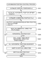
- FIG. 1 is a block diagram of a face detection unit for detecting a face as a specific object, in an image processing apparatus according to a first embodiment of the present invention.
- FIG. 2 is a flowchart of a sub window position control process executed by the image processing apparatus in FIG. 1 .
- FIG. 3 is an explanatory diagram showing movement of a sub window position, performed in the sub window position control process in FIG. 2 .
- FIG. 4 is a timing diagram of a sub window image process executed by the image processing apparatus in FIG. 1 .
- FIG. 5 is a block diagram of a face detection unit for detecting a face as a specific object, in an image processing apparatus according to a second embodiment of the present invention.
- FIG. 6 is an explanatory diagram of a face detection process executed by the image processing apparatus in FIG. 5 .
- FIGS. 7A to 7C are explanatory diagrams of a process for determining a specific object executed by a determination processing section of a conventional image processing apparatus.
- FIG. 8 is a flowchart of a sub window position control process executed by the conventional image processing apparatus.
- FIG. 9 is an explanatory diagram showing movement of a sub window position during the sub window position control process executed by the conventional image processing apparatus.
- FIG. 10 is a timing diagram of a sub window image process executed by the conventional image processing apparatus.
- FIG. 1 is a block diagram of a face detection unit for detecting a face as a specific object, in an image processing apparatus according to a first embodiment of the present invention.
- the face detection unit is comprised of an image storage section 101 , a small-area image acquisition section 102 , a scanning position control section 103 , a determination result storage section 104 , a determination section 105 , and a dictionary storage section 106 .
- the image storage section 101 stores input images, and it is possible to randomly access each of pixels of an input image.
- the scanning position control section 103 sequentially determines the position of a sub window to be processed for determination.
- the small-area image acquisition section 102 reads a sub window image (small-area image) in the position determined by the scanning position control section 103 , and supplies the sub window image to the determination section 105 .
- the determination section 105 refers to dictionary data stored in the dictionary storage section 106 , and determines whether or not there is a face in the sub window image. A result of the determination is stored in the determination result storage section 104 together with sub window position information.
- the dictionary data used by the determination section 105 is stored in the dictionary storage section 106 , and a coefficient required for determination and a look-up table (LUT) data and the like are also stored in the dictionary storage section 106 .
- LUT look-up table
- the scanning position control section 103 sequentially computes the position of a sub window image using a predetermined skip amount in a predetermined scanning direction. Further, the scanning position control section 103 repeatedly carries out scanning of skipped sub window images each time shifting the start point for scanning, to thereby control positions of all of the sub window images which are subject to the detection of a face as the specific object.
- FIG. 2 is a flowchart of a sub window position control process executed by the image processing apparatus in FIG. 1 .
- FIG. 3 is an explanatory diagram showing movement of the sub window position, performed in the flowchart in FIG. 2 .
- the present process is executed by the scanning position control section 103 in FIG. 1 .
- the small-area image acquisition section 102 acquires each image of a sub window in the shifted position, and outputs the same to the determination section 105 .
- the scanning position control section 103 performs processing for determining the left upper coordinate position of a sub window in an input image 301 in FIG. 3 .
- the scanning position control section 103 initializes a vertical position Pv to 0 to set a start position of a sub window to be extracted.
- the scanning position control section 103 sets a variable, referred to as a horizontal position offset Offseth, to hold an offset amount in the horizontal direction, and initializes the variable by 0.
- a horizontal position offset Offseth a variable that holds an offset amount in the horizontal direction
- a step S 203 the scanning position control section 103 initializes a horizontal position Ph by 0 to set the start position of the sub window to be extracted.
- the scanning position control section 103 computes the position of the sub window, which is to be notified to the small-area image acquisition section 102 .
- An output horizontal position Outh to be notified is a value obtained by adding the horizontal position offset Offseth to the horizontal position Ph, and an output vertical position Outv is the vertical position Pv.
- the first output position is the position of a sub window 302 .
- a step S 205 is a process for moving the position in the horizontal direction, and the scanning position control section 103 updates the horizontal position Ph to the value obtained by adding a skip amount Skiph to the horizontal position Ph.
- the skip amount Skiph for example, uses the number of pixels corresponding to the width of a possible face image.
- the position moved from the sub window 302 by processing in the step S 205 is the position of a sub window 303 .
- the scanning position control section 103 checks whether or not the sub window position is a horizontal end position.
- the horizontal end position is the position of a sub window 304 .
- the position of the sub window 304 is a horizontal end position of a sub window which can be extracted from the input image 301 by the skip amount Skiph and is closest to a horizontal end of the input image 301 .
- the process returns to the step S 204 to repeat the processing for moving the position of the sub window, using the skip amount Skiph in the horizontal direction, until the position reaches the horizontal end position.
- a step S 207 the scanning position control section 103 performs processing for adding 1 to the horizontal position offset Offseth to set an offset to the next scan position in the horizontal direction.
- the scanning position control section 103 checks whether or not all the positions have been scanned for the horizontal direction.
- the scanning position control section 103 causes the respective positions of sub windows to be each determined after skipping over the skip amount Skiph, and causes all positions of sub windows in the skipped portions to be determined using the horizontal position offset Offseth in the second and subsequent executions of scanning.
- step S 208 it is only required to check whether or not the horizontal position offset Offseth becomes equal to the value of the skip amount Skiph.
- a first-time scan brings the sub window position to the position of the sub window 304 , and hence it is determined in the step S 208 that there are skipped portions, so that the answer to the question of the step S 208 is negative (NO). Therefore, the process returns to the step S 203 to perform a second-time scan.
- the second-time scan is started from the position of a sub window 305 .
- the position of the sub window 305 is offset, i.e. shifted in the horizontal direction by the horizontal position offset Offseth from the sub window 302 which is the start position of the first-time scan.
- the second-time scan sequentially proceeds to a sub window 305 , a sub window 306 , and so on, each time skipping over the skip amount Skiph.
- a step S 209 the position of a sub window is shifted by one pixel in the vertical direction. Specifically, the scanning position control section 103 causes the vertical position Pv to be incremented by 1 to thereby update the vertical position Pv.
- a step S 210 the scanning position control section 103 checks whether or not the sub window is moved to the position of a sub window 307 , i.e. a vertical end position of the sub window. If the sub window is not moved to the vertical end position, the answer to this question is negative (NO), so that the process returns to the step S 202 to perform scanning all positions for the horizontal direction.
- the sub window is in a position shifted from the sub window 302 by the Pv pixels in the vertical direction.
- the processing for scanning all positions in a skipping fashion in the horizontal direction is advanced in a manner shifting in the vertical direction.
- This processing is repeated until the position of the sub window reaches the position of the sub window 307 , i.e. the end position.
- the answer to the question of the step S 210 becomes affirmative (YES), so that the whole loop is terminated.
- the position control shown in the present embodiment is performed by determining all horizontal positions in the same vertical position, and then shifting the vertical position.
- this method is identical to the above-described method of the position control of the present embodiment in respect of the point that the image is repeatedly scanned in a skipping manner, thereby determining all the positions of sub windows.
- FIG. 4 is a timing diagram of a sub window image process executed by the image processing apparatus in FIG. 1 .
- the face images 1 , 2 , and 3 are successive, and then, non-face images 4 to 9 are successive.
- a non-face image is put between successive face images in the order of processing, which make it possible to reduce occurrence of waiting for completion of processing before a position shift.
- FIG. 4 since the non-face images corresponding to not shorter than processing time required by the stage 2 are put between the face images, it is possible to completely eliminate the occurrence of waiting for completion of processing before a position shift.
- the skip amount Skiph used by the scanning position control section 103 is set to a selected appropriate one of the skip amounts stored in the dictionaries, which makes it possible to perform scanning in which the processing load is dispersed.
- an area of a face and an area in the vicinity of the face are different between a case where a face is detected using a dictionary for a sub window of 10 ⁇ 10 pixels, and a case where a face is detected by a dictionary for a sub window of 20 ⁇ 20 pixels.
- a skip amount of 4 pixels is optimum for the sub window of 10 ⁇ 10 pixels, it is favorable to double the skip amount to 8 pixels for the sub window of 20 ⁇ 20 pixels.
- FIG. 5 is a block diagram of a face detection unit for detecting a face as a specific object, in an image processing apparatus according to a second embodiment of the present invention.
- a skip amount calculation section 107 appearing in in FIG. 5 may be provided for calculation of the skip amount.
- Sub window sizes are stored in advance in the dictionary storage section 106 in association with respective dictionaries, and the skip amount calculation section 107 determines a skip amount by multiplying, by a predetermined coefficient, a sub window size associated with a dictionary which is selected by switching between the dictionaries.
- This calculation is not limited to the multiplication using the predetermined coefficient, but it is only required to determine the skip amount from a sub window size by a predetermined calculation formula.
- the sub window size is sometimes required to be changed when an object to be recognized is changed, and in this case, it is possible to calculate an appropriate skip amount from the sub window size. This makes it possible to set the appropriate skip amount, so that it possible to maintain dispersibility of heavy load processing.
- FIG. 6 is an explanatory diagram of a face detection process executed by the image processing apparatus in FIG. 5 .
- the skin color portions become face parts and portions of background and arms in skin color, as shown by an area 602 , and hence the detection process is performed on the area 602 .
- the present invention to the area 602 extracted by the aforementioned preprocessing to perform scanning such that the preprocessed data is read out in a skipping manner, it is possible to obtain the same advantageous effects.
Landscapes
- Engineering & Computer Science (AREA)
- Theoretical Computer Science (AREA)
- Computer Vision & Pattern Recognition (AREA)
- Health & Medical Sciences (AREA)
- Multimedia (AREA)
- General Physics & Mathematics (AREA)
- Physics & Mathematics (AREA)
- General Health & Medical Sciences (AREA)
- Computing Systems (AREA)
- Software Systems (AREA)
- Medical Informatics (AREA)
- Evolutionary Computation (AREA)
- Databases & Information Systems (AREA)
- Artificial Intelligence (AREA)
- Oral & Maxillofacial Surgery (AREA)
- Human Computer Interaction (AREA)
- Image Analysis (AREA)
- Image Processing (AREA)
Abstract
Description
Claims (4)
Applications Claiming Priority (3)
| Application Number | Priority Date | Filing Date | Title |
|---|---|---|---|
| JP2008-259764 | 2008-10-06 | ||
| JP2008259764A JP5311958B2 (en) | 2008-10-06 | 2008-10-06 | Image processing apparatus and image processing method |
| JP2008-259764(PAT.) | 2008-10-06 |
Publications (2)
| Publication Number | Publication Date |
|---|---|
| US20100086177A1 US20100086177A1 (en) | 2010-04-08 |
| US8369573B2 true US8369573B2 (en) | 2013-02-05 |
Family
ID=42075854
Family Applications (1)
| Application Number | Title | Priority Date | Filing Date |
|---|---|---|---|
| US12/574,274 Expired - Fee Related US8369573B2 (en) | 2008-10-06 | 2009-10-06 | Image processing apparatus and method |
Country Status (2)
| Country | Link |
|---|---|
| US (1) | US8369573B2 (en) |
| JP (1) | JP5311958B2 (en) |
Families Citing this family (1)
| Publication number | Priority date | Publication date | Assignee | Title |
|---|---|---|---|---|
| US20140314273A1 (en) * | 2011-06-07 | 2014-10-23 | Nokia Corporation | Method, Apparatus and Computer Program Product for Object Detection |
Citations (1)
| Publication number | Priority date | Publication date | Assignee | Title |
|---|---|---|---|---|
| US20090245570A1 (en) * | 2008-03-28 | 2009-10-01 | Honeywell International Inc. | Method and system for object detection in images utilizing adaptive scanning |
Family Cites Families (3)
| Publication number | Priority date | Publication date | Assignee | Title |
|---|---|---|---|---|
| JP2002310618A (en) * | 2001-04-19 | 2002-10-23 | Murata Mfg Co Ltd | Size measurement device, size measurement method and inspection device for electronic component |
| JP2005215899A (en) * | 2004-01-28 | 2005-08-11 | Yamaha Motor Co Ltd | Object detection apparatus and method |
| JP4628882B2 (en) * | 2005-06-16 | 2011-02-09 | 富士フイルム株式会社 | Classifier learning method, face discrimination method and apparatus, and program |
-
2008
- 2008-10-06 JP JP2008259764A patent/JP5311958B2/en not_active Expired - Fee Related
-
2009
- 2009-10-06 US US12/574,274 patent/US8369573B2/en not_active Expired - Fee Related
Patent Citations (1)
| Publication number | Priority date | Publication date | Assignee | Title |
|---|---|---|---|---|
| US20090245570A1 (en) * | 2008-03-28 | 2009-10-01 | Honeywell International Inc. | Method and system for object detection in images utilizing adaptive scanning |
Non-Patent Citations (1)
| Title |
|---|
| Paul Viola and Michael Jones, Robust Real Time Object Detection, Second International Workshop on Statistical and Computational Theories of Vision-Modeling, Learning, Computing, and Sampling, Jul. 13, 2001, Vancouver, Canada. |
Also Published As
| Publication number | Publication date |
|---|---|
| JP2010092162A (en) | 2010-04-22 |
| JP5311958B2 (en) | 2013-10-09 |
| US20100086177A1 (en) | 2010-04-08 |
Similar Documents
| Publication | Publication Date | Title |
|---|---|---|
| US7412080B2 (en) | Adaptive motion estimation | |
| US20110211233A1 (en) | Image processing device, image processing method and computer program | |
| JP3233895B2 (en) | Display device and driving method thereof | |
| EP3306562A1 (en) | Image processing method and device | |
| US20150248776A1 (en) | Image capturing apparatus, image capturing system, and image capturing method | |
| JP2002216116A (en) | Input method of fingerprint image, input device of fingerprint image, program and portable information terminal | |
| JP2017069946A (en) | Image processing system and image processing method | |
| US8369573B2 (en) | Image processing apparatus and method | |
| JP2010102584A (en) | Image processor and image processing method | |
| JP2010165052A (en) | Image processor and image processing method | |
| US7912128B2 (en) | Motion vector estimation system and method thereof | |
| US8306320B2 (en) | 2D image segmentation apparatus and method, and apparatus and method for removing red-eye in the image | |
| US20110019879A1 (en) | Adaptive Motion Estimation | |
| US10951870B2 (en) | Digital image conversion method and apparatus, storage medium, and device | |
| CN119049429B (en) | Brightness compensation method and device for display panel, and display device | |
| JP2009164674A (en) | Distortion correction device | |
| US20030067986A1 (en) | Circuit and method for full search block matching | |
| US9083912B2 (en) | Method and apparatus for enabling parallel processing of pixels in an image | |
| US20110001882A1 (en) | Method and system for determining motion vectors for flat regions | |
| WO2018189772A1 (en) | Correlation value calculation device | |
| JP5005482B2 (en) | Pattern search method and apparatus | |
| JP4193387B2 (en) | Device for extracting motion parameters between images | |
| KR101620928B1 (en) | Fast face detection system using priority address allocation and moving window technique | |
| CN101459761A (en) | Image processing method and related device thereof | |
| JPH07288817A (en) | Motion vector detector |
Legal Events
| Date | Code | Title | Description |
|---|---|---|---|
| AS | Assignment |
Owner name: CANON KABUSHIKI KAISHA,JAPAN Free format text: ASSIGNMENT OF ASSIGNORS INTEREST;ASSIGNORS:HASHIGUCHI, NORIYASU;OSA, KINYA;REEL/FRAME:023803/0953 Effective date: 20091015 Owner name: CANON KABUSHIKI KAISHA, JAPAN Free format text: ASSIGNMENT OF ASSIGNORS INTEREST;ASSIGNORS:HASHIGUCHI, NORIYASU;OSA, KINYA;REEL/FRAME:023803/0953 Effective date: 20091015 |
|
| STCF | Information on status: patent grant |
Free format text: PATENTED CASE |
|
| FPAY | Fee payment |
Year of fee payment: 4 |
|
| FEPP | Fee payment procedure |
Free format text: MAINTENANCE FEE REMINDER MAILED (ORIGINAL EVENT CODE: REM.); ENTITY STATUS OF PATENT OWNER: LARGE ENTITY |
|
| LAPS | Lapse for failure to pay maintenance fees |
Free format text: PATENT EXPIRED FOR FAILURE TO PAY MAINTENANCE FEES (ORIGINAL EVENT CODE: EXP.); ENTITY STATUS OF PATENT OWNER: LARGE ENTITY |
|
| STCH | Information on status: patent discontinuation |
Free format text: PATENT EXPIRED DUE TO NONPAYMENT OF MAINTENANCE FEES UNDER 37 CFR 1.362 |
|
| FP | Lapsed due to failure to pay maintenance fee |
Effective date: 20210205 |