US8362702B2 - Local dimming control method and apparatus of edge-type backlight module - Google Patents
Local dimming control method and apparatus of edge-type backlight module Download PDFInfo
- Publication number
- US8362702B2 US8362702B2 US12/696,043 US69604310A US8362702B2 US 8362702 B2 US8362702 B2 US 8362702B2 US 69604310 A US69604310 A US 69604310A US 8362702 B2 US8362702 B2 US 8362702B2
- Authority
- US
- United States
- Prior art keywords
- display
- dimming control
- local dimming
- backlight units
- display area
- Prior art date
- Legal status (The legal status is an assumption and is not a legal conclusion. Google has not performed a legal analysis and makes no representation as to the accuracy of the status listed.)
- Active, expires
Links
- 238000000034 method Methods 0.000 title claims abstract description 22
- 239000011159 matrix material Substances 0.000 claims description 8
- 238000010586 diagram Methods 0.000 description 3
- 239000004973 liquid crystal related substance Substances 0.000 description 2
- 230000003287 optical effect Effects 0.000 description 2
- 230000004075 alteration Effects 0.000 description 1
- 238000012986 modification Methods 0.000 description 1
- 230000004048 modification Effects 0.000 description 1
Images


Classifications
-
- G—PHYSICS
- G09—EDUCATION; CRYPTOGRAPHY; DISPLAY; ADVERTISING; SEALS
- G09G—ARRANGEMENTS OR CIRCUITS FOR CONTROL OF INDICATING DEVICES USING STATIC MEANS TO PRESENT VARIABLE INFORMATION
- G09G3/00—Control arrangements or circuits, of interest only in connection with visual indicators other than cathode-ray tubes
- G09G3/20—Control arrangements or circuits, of interest only in connection with visual indicators other than cathode-ray tubes for presentation of an assembly of a number of characters, e.g. a page, by composing the assembly by combination of individual elements arranged in a matrix no fixed position being assigned to or needed to be assigned to the individual characters or partial characters
- G09G3/34—Control arrangements or circuits, of interest only in connection with visual indicators other than cathode-ray tubes for presentation of an assembly of a number of characters, e.g. a page, by composing the assembly by combination of individual elements arranged in a matrix no fixed position being assigned to or needed to be assigned to the individual characters or partial characters by control of light from an independent source
- G09G3/3406—Control of illumination source
- G09G3/342—Control of illumination source using several illumination sources separately controlled corresponding to different display panel areas, e.g. along one dimension such as lines
- G09G3/3426—Control of illumination source using several illumination sources separately controlled corresponding to different display panel areas, e.g. along one dimension such as lines the different display panel areas being distributed in two dimensions, e.g. matrix
Definitions
- the disclosed embodiments of the present invention relate to controlling a backlight module, and more particularly, to a local dimming control apparatus and method of an edge-type backlight module.
- a light source of a direct-type backlight module is commonly implemented by fluorescent tube(s). Due to the advance of the LCD technology, a partially-driven direct-type backlight module is developed, where a number of point light sources, such as light emitting diodes (LEDs), are used in a plurality of backlight units disposed below a plurality of regions of a display panel and implemented for illuminating the regions, respectively and independently. Therefore, the light intensity of the backlight module is partially changed rather than globally changed, which can improve the display quality of the video image.
- LEDs light emitting diodes
- an edge-type backlight module is preferred.
- the conventional edge-type backlight module has a number of point light sources, such as LEDs arranged at a side of the LCD panels. As the local dimming control of the backlight module would affect the final display quality of the video image, how to properly control the edge-type backlight module becomes an important topic to designers in this field.
- a local dimming control apparatus and method of an edge-type backlight module are proposed.
- a local dimming control apparatus of an edge-type backlight module has a plurality of backlight units positioned at least one side of a display area.
- the local dimming control apparatus includes: a configuration unit, for dividing the display area into a plurality of display blocks; and a local dimming control unit, coupled to the configuration unit, for setting respective backlight intensities of the display blocks through controlling a plurality of luminance settings of the backlight units.
- a local dimming control method of an edge-type backlight module is proposed.
- the edge-type backlight module has a plurality of backlight units positioned at least one side of a display area.
- the local dimming control method includes the following steps: dividing the display area into a plurality of display blocks; and performing a local dimming control operation to set respective backlight intensities of the display blocks through controlling a plurality of luminance settings of the backlight units.
- FIG. 1 is a block diagram illustrating a display system according to an exemplary embodiment of the present invention.
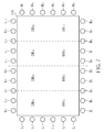
- FIG. 2 shows a first panel division of a display panel shown in FIG. 1 .
- FIG. 3 shows a second panel division of the display panel shown in FIG. 1 .
- FIG. 4 shows a third panel division of the display panel shown in FIG. 1 .
- FIG. 5 shows a fourth panel division of the display panel shown in FIG. 1 .
- FIG. 6 is a flowchart of a generalized local dimming control method of an edge-type backlight module according to an exemplary embodiment of the present invention.
- FIG. 7 shows a fifth panel division of the display panel shown in FIG. 1 .
- FIG. 1 is a block diagram illustrating a display system according to an exemplary embodiment of the present invention.
- the display system 100 includes, but is not limited to, a local dimming control apparatus 102 , an edge-type backlight module 104 , and a display panel 106 having a display area 108 .
- the edge-type backlight module 104 has a plurality of backlight units 105 positioned at least one side of the display area 108 , where each of the backlight units 105 has at least one light source.
- the edge-type backlight module 104 is a light-emitting diode (LED) backlight module, and each backlight unit 105 contains at least one LED.
- the display area 108 includes a plurality of pixels.
- the display panel 108 is a liquid crystal display (LCD) panel, and the pixels thereof are made of LCD units.
- the exemplary local dimming control apparatus 102 includes a configuration unit 110 and a local dimming control unit 120 .
- the configuration unit 110 is devised for dividing the display area 108 into a plurality of display blocks.
- the local dimming control unit 112 coupled to the configuration unit 110 , is implemented for setting luminance values (backlight intensities) of the display blocks by controlling a plurality of luminance settings of the backlight units 105 .
- the operation of the exemplary local dimming control apparatus 102 is detailed as follows.
- FIG. 2 shows a first panel division of the display panel 106 shown in FIG. 1 .
- the edge-type backlight module 104 has 2*(10+6) backlight units 105 positioned at four sides of the rectangular display area 108 .
- ten backlight units U 1 -U 10 are positioned at the top side of the display area 108
- ten backlight units B 1 -B 10 are positioned at the bottom side of the display area 108
- six backlight units L 1 -L 6 are positioned at the left side of the display area 108
- six backlight units R 1 -R 6 are positioned at the right side of the display area 108 .
- the display area 108 of the display panel 106 is divided into 10*6 display blocks DB 11 -DB 16 , DB 21 -DB 26 , . . . , DB 101 -DB 106 .
- the local dimming control unit 112 is devised to set a luminance of each display block by controlling luminance settings of all the backlight units 105 .
- the luminance value of each display block would be a combination (e.g., a weighted combination) of luminance values of all the backlight units 105 .
- D MN u 1 — MN ⁇ U 1 +u 2 — MN ⁇ U 2 + . . . +u 10 — MN ⁇ U 10 +b 1 — MN ⁇ B 1 +b 2 — MN ⁇ B 2 + . . . +b 10 — MN ⁇ B 10 +l 1 — MN ⁇ L 1 +l 2 — MN ⁇ L 2 + . . . +l 6 — MN ⁇ L 6 +r 1 — MN ⁇ R 1 +r 2 — MN ⁇ R 2 + . . . +r 6 — MN ⁇ R 6 (1)
- u 1 — MN -u 10 — MN are weighting factors of the luminance values of the backlight units U 1 -U 10 for the display block DB MN
- b 1 — MN -b 10 — MN are weighting factors of the luminance values of the backlight units B 1 -B 10 for the display block DB MN
- l 1 — MN -l 6 — MN are weighting factors of the luminance values of the backlight units L 1 -L 6 for the display block DB MN
- r 1 — MN -r 6 — MN are weighting factors of the luminance values of the backlight units R 1 -R 6 for the display block DB MN .
- the aforementioned weighting factors u 1 — MN -u 10 — MN , b 1 — MN -b 10 — MN , l 1 — MN -l 6 — MN and r 1 — MN -r 6 — MN for the display block DB MN are fixed and pre-defined according to optical characteristics of the backlight units U 1 -U 10 , B 1 -B 10 , L 1 -L 6 and R 1 -R 6 . More specifically, with a proper design of a light guide plate of the edge-type backlight module 104 , a luminance contribution of a backlight unit may be uniform within the target display block DB MN . Thus, a weighting factor of the backlight unit is therefore constant and known.
- the desired luminance of each of the display blocks DB 11 -DB 16 , DB 21 -DB 26 , . . . , DB 101 -DB 106 can be expressed according to equation (1).
- the desired luminance D 11 and D 12 thereof can be expressed as follows.
- D 11 u 1 — 11 ⁇ U 1 +u 2 — 11 ⁇ U 2 + . . .
- 10*6 display blocks DB 11 -DB 16 , DB 21 -DB 26 , . . . , DB 101 -DB 106 10*6 equations are required to express the desired luminance values of the display blocks DB 11 -DB 16 , DB 21 -DB 26 , . . .
- DB 101 -DB 106 in terms of luminance values of the backlight units U 1 -U 10 , B 1 -B 10 , L 1 -L 6 and R 1 -R 6 ; however, only 2*(10+6) variables (i.e., luminance values of backlight units U 1 -U 10 , B 1 -B 10 , L 1 -L 6 and R 1 -R 6 to be controlled) are included therein due to the fact that the desired luminance values (i.e., D 11 -D 16 , D 21 -D 26 , . . . , D 101 -D 106 ) and all the weighting factors are known. Since the number of variables is smaller than the number of equations (i.e., 2*(10+6) ⁇ 10*6), no solution can be successfully found. As a result, the local dimming control would fail under such a panel division.
- the configuration unit 110 is particularly devised to divide the display area 108 into a plurality of display blocks according to the number of the backlight units 105 included in the edge-type backlight module 104 .
- the number of the configured display blocks is equal to the number of the backlight units 105 .
- the backlight intensity provided by a backlight unit may be zero or other luminance value.
- the number of the configured display blocks is smaller than the number of the backlight units as shown in FIG. 7 , which illustrates a fifth panel division of the display panel shown in FIG. 1 .
- FIG. 7 which illustrates a fifth panel division of the display panel shown in FIG. 1 .
- any of the solutions can be used to set the luminance values of the backlight units 105 .
- FIG. 3 shows a second panel division of the display panel 106 shown in FIG. 1 .
- the display blocks DB 11 -DB 14 , DB 21 -DB 24 , . . . , DB 81 -DB 84 are configured by the configuration unit 110 and arranged in a matrix format.
- the luminance value of each display block is a combination (e.g., a weighted combination) of luminance values of all the backlight units 105 .
- D′ MN u′ 1 — MN ⁇ U 1 +u′ 2 — MN ⁇ U 2 + . . . +u′ 10 — MN ⁇ U 10 +b′ 1 — MN ⁇ B 1 +b′ 2 — MN ⁇ B 2 + . . . +b′ 10 — MN ⁇ B 10 +l′ 1 — MN ⁇ L 1 +l′ 2 — MN ⁇ L 2 + . . . +l′ 6 — MN ⁇ L 6 +r′ 1 — MN ⁇ R 1 +r′ 2 — MN ⁇ R 2 + . . . +r′ 6 — MN ⁇ R 6 (4)
- 8*4 display blocks DB 11 -DB 14 , DB 21 -DB 24 , . . . , DB 81 -DB 84 8*4 equations are required to express the desired luminance values of the display blocks DB 11 -DB 14 , DB 21 -DB 24d , . . . , DB 81 -DB 84 .
- 2*(10+6) variables i.e., luminance values of backlight units U 1 -U 10 , B 1 -B 10 , L 1 -L 6 and R 1 -R 6 to be controlled
- the desired luminance values i.e., D′ 11 -D′ 14 , D′ 21 -D′ 24 , . . . , D′ 81 -D′ 84
- FIG. 4 shows a third panel division of the display panel 106 shown in FIG. 1 .
- the display blocks DB 1 -DB 32 are configured by the configuration unit 110 and arranged in a radial format.
- 8*4 equations are required to express the desired luminance values of the display blocks DB 1 -DB 32 .
- 2*(10+6) variables i.e., luminance values of backlight units U 1 -U 10 , B 1 -B 10 , L 1 -L 6 and R 1 -R 6 to be controlled
- the desired luminance values i.e., D 1 -D 32
- the edge-type backlight module 104 has backlight units 105 positioned at four sides of the rectangular display area 108 .
- the same objective of performing local dimming control upon the edge-type backlight module 104 can be achieved.
- FIG. 5 shows a fourth panel division of the display panel 106 shown in FIG. 1 .
- the edge-type backlight module 104 has 2*10 backlight units 105 positioned at two sides of the rectangular display area 108 . As shown in FIG.
- the display area 108 of the display panel 106 is divided into 10*2 display blocks DB 11 -DB 16 , DB 21 -DB 22 , . . . , DB 101 -DB 102 , and the display blocks DB 11 -DB 16 , DB 21 -DB 22 , . . . , DB 101 -DB 102 configured by the configuration unit 110 are arranged in a matrix format.
- 10*2 display blocks DB 11 -DB 21 , DB 21 -DB 22 , . . . , DB 101 -DB 102 10*2 equations are required to express the desired luminance values of the display blocks DB 11 -DB 21 , DB 21 -DB 22 , . . . , DB 101 -DB 102 .
- 2*10 variables i.e., luminance values of backlight units U 1 -U 10 and B 1 -B 10 to be controlled
- the desired luminance values i.e., D′′ 11 -D′′ 12 , D′′ 21 -D′′ 22 , . . .
- the local dimming control can be successfully performed upon each display block through controlling luminance settings of all backlight units 105 as long as the configuration unit 110 divides the display area 108 of the display panel 106 into display blocks whose number is not greater than the number of the backlight units 105 .
- the size and/or the shape of the configured display block can be adjustable, depending upon design requirements. For example, the display blocks are not required to be arranged in the matrix format or radial format, and the display blocks are not required to have the same size/shape.
- any rule of defining the display blocks in the display area can be employed by the configuration unit 110 shown in FIG. 1 .
- FIG. 6 is a flowchart of a generalized local dimming control method of an edge-type backlight module according to an exemplary embodiment of the present invention.
- the edge-type backlight module has a plurality of backlight units positioned at sides of a display area. If the result is substantially the same, the steps are not required to be executed in the exact order shown in FIG. 6 .
- the exemplary local dimming control method can be briefly summarized as follows.
- Step 602 Divide the display area into a plurality of display blocks according to the number of the backlight units.
- the number of the display blocks is equal to or smaller than the number of the backlight units; in addition, the display blocks may be arranged in a matrix format or a radial format.
- Step 604 For each of the display blocks, set a luminance value (backlight intensity) of the display block by controlling a plurality of luminance settings of the backlight units. Therefore, the local dimming control applied to the backlight intensities of the display blocks is achieved through controlling the luminance settings of the backlight units. As the number of variables is equal to or smaller than the number of equations, at least one solution can be found. Thus, based on the found solution of the luminance settings (luminance values) of the backlight units, the local dimming control can be successfully realized.
Landscapes
- Engineering & Computer Science (AREA)
- Physics & Mathematics (AREA)
- Computer Hardware Design (AREA)
- General Physics & Mathematics (AREA)
- Theoretical Computer Science (AREA)
- Liquid Crystal Display Device Control (AREA)
- Control Of Indicators Other Than Cathode Ray Tubes (AREA)
- Liquid Crystal (AREA)
Abstract
Description
D MN =u 1
D 11 =u 1
D 12 =u 1
D′ MN =u′ 1
D M =u 1
D″ MN =u″ 1
Claims (20)
Priority Applications (3)
| Application Number | Priority Date | Filing Date | Title |
|---|---|---|---|
| US12/696,043 US8362702B2 (en) | 2010-01-28 | 2010-01-28 | Local dimming control method and apparatus of edge-type backlight module |
| TW099118792A TWI420468B (en) | 2010-01-28 | 2010-06-09 | Regional dimming control device and regional dimming control method |
| CN2010102043696A CN102142233A (en) | 2010-01-28 | 2010-06-21 | Regional dimming control device and regional dimming control method |
Applications Claiming Priority (1)
| Application Number | Priority Date | Filing Date | Title |
|---|---|---|---|
| US12/696,043 US8362702B2 (en) | 2010-01-28 | 2010-01-28 | Local dimming control method and apparatus of edge-type backlight module |
Publications (2)
| Publication Number | Publication Date |
|---|---|
| US20110181202A1 US20110181202A1 (en) | 2011-07-28 |
| US8362702B2 true US8362702B2 (en) | 2013-01-29 |
Family
ID=44308443
Family Applications (1)
| Application Number | Title | Priority Date | Filing Date |
|---|---|---|---|
| US12/696,043 Active 2030-10-31 US8362702B2 (en) | 2010-01-28 | 2010-01-28 | Local dimming control method and apparatus of edge-type backlight module |
Country Status (3)
| Country | Link |
|---|---|
| US (1) | US8362702B2 (en) |
| CN (1) | CN102142233A (en) |
| TW (1) | TWI420468B (en) |
Families Citing this family (6)
| Publication number | Priority date | Publication date | Assignee | Title |
|---|---|---|---|---|
| CN103106875B (en) * | 2011-11-11 | 2015-09-23 | 联咏科技股份有限公司 | Image display device, display control device and screen control chip |
| CN103165081B (en) * | 2011-12-19 | 2015-12-02 | Tcl光电科技(惠州)有限公司 | LED-backlit module and dynamic light adjustment method thereof |
| US10262599B2 (en) * | 2017-03-24 | 2019-04-16 | Intel Corporation | Display backlight brightness adjustment |
| CN110211540A (en) * | 2019-05-30 | 2019-09-06 | 深圳创维-Rgb电子有限公司 | A kind of multi-region method for controlling backlight thereof, device, terminal and storage medium |
| US11281047B1 (en) * | 2020-12-01 | 2022-03-22 | Solomon Systech (China) Limited | Backlight generation with local dimming for liquid crystal panel having arbitrary shape |
| CN117292655A (en) * | 2022-06-17 | 2023-12-26 | 苏州佳世达电通有限公司 | Backlight device for improving dynamic blur, operating method and display device |
Citations (5)
| Publication number | Priority date | Publication date | Assignee | Title |
|---|---|---|---|---|
| US20080309611A1 (en) * | 2007-06-15 | 2008-12-18 | Lg.Display Co., Ltd. | Driving circuit of liquid crystal display device and method for driving the same |
| US20090015755A1 (en) | 2007-06-01 | 2009-01-15 | Lg Display Co., Ltd. | Liquid crystal display device |
| US20090027592A1 (en) * | 2007-07-25 | 2009-01-29 | Nec Lcd Technologies, Ltd. | Display device, manufacturing method of display device, and manufacturing apparatus for the same |
| US20090140665A1 (en) * | 2007-12-04 | 2009-06-04 | Mun-Soo Park | Light source module, method for driving the light source module, display device having the light source module |
| US7658528B2 (en) * | 2004-12-09 | 2010-02-09 | Koninklijke Philips Electronics, N.V. | Illumination system |
Family Cites Families (5)
| Publication number | Priority date | Publication date | Assignee | Title |
|---|---|---|---|---|
| TWI345655B (en) * | 2006-03-17 | 2011-07-21 | Chimei Innolux Corp | Liquid crystal display device and method of modulating backlight |
| KR101297248B1 (en) * | 2006-06-23 | 2013-08-19 | 엘지디스플레이 주식회사 | Backlight of liquid crystal display device and driving method thereof |
| US20080186734A1 (en) * | 2007-02-02 | 2008-08-07 | Kong Kong Applied Science And Technology Research Institute Co., Ltd. | Side-emitting backlight system and backlit display using the same |
| CN101303839A (en) * | 2007-05-08 | 2008-11-12 | 日本胜利株式会社 | Liquid crystal display device and image display method thereof |
| CN201363668Y (en) * | 2009-03-11 | 2009-12-16 | 冠捷投资有限公司 | Side light type backlight module |
-
2010
- 2010-01-28 US US12/696,043 patent/US8362702B2/en active Active
- 2010-06-09 TW TW099118792A patent/TWI420468B/en not_active IP Right Cessation
- 2010-06-21 CN CN2010102043696A patent/CN102142233A/en active Pending
Patent Citations (5)
| Publication number | Priority date | Publication date | Assignee | Title |
|---|---|---|---|---|
| US7658528B2 (en) * | 2004-12-09 | 2010-02-09 | Koninklijke Philips Electronics, N.V. | Illumination system |
| US20090015755A1 (en) | 2007-06-01 | 2009-01-15 | Lg Display Co., Ltd. | Liquid crystal display device |
| US20080309611A1 (en) * | 2007-06-15 | 2008-12-18 | Lg.Display Co., Ltd. | Driving circuit of liquid crystal display device and method for driving the same |
| US20090027592A1 (en) * | 2007-07-25 | 2009-01-29 | Nec Lcd Technologies, Ltd. | Display device, manufacturing method of display device, and manufacturing apparatus for the same |
| US20090140665A1 (en) * | 2007-12-04 | 2009-06-04 | Mun-Soo Park | Light source module, method for driving the light source module, display device having the light source module |
Also Published As
| Publication number | Publication date |
|---|---|
| TWI420468B (en) | 2013-12-21 |
| CN102142233A (en) | 2011-08-03 |
| TW201126495A (en) | 2011-08-01 |
| US20110181202A1 (en) | 2011-07-28 |
Similar Documents
| Publication | Publication Date | Title |
|---|---|---|
| CN102804035B (en) | Liquid crystal indicator and driving method thereof | |
| US8362702B2 (en) | Local dimming control method and apparatus of edge-type backlight module | |
| EP1717792A2 (en) | Backlight unit for dynamic images and display device employing the same | |
| JP2009053687A (en) | Backlight unit and method of using the same | |
| US20130321495A1 (en) | Display device | |
| KR20100095282A (en) | Method of driving a light-source | |
| US20130342430A1 (en) | Color sequential image method and system thereof | |
| US20090303167A1 (en) | Liquid Crystal Display Device | |
| US10332457B2 (en) | Display apparatus and method of driving the same | |
| US20170116928A1 (en) | Backlight unit and display apparatus including the same | |
| US20110316872A1 (en) | Image displaying method, device, and related liquid crystal display panel | |
| US20070115648A1 (en) | Light source structure of backlight module | |
| CN103778898A (en) | Dynamic dimming method of liquid crystal display LED backlight | |
| US20150179111A1 (en) | Liquid crystal display device as well as backlight source and dimming method for the same | |
| WO2011043094A1 (en) | Lighting device and display device | |
| US20150035867A1 (en) | Liquid crystal display device and method of driving the same | |
| EP2375140A1 (en) | Display apparatus and backlight unit | |
| KR101588340B1 (en) | Display device and method for driving the same | |
| JP4332565B2 (en) | A device in which three primary color light emitting diodes are arranged in a matrix | |
| WO2013073428A1 (en) | Display device | |
| KR100739536B1 (en) | Light source system and control method of light source system | |
| US8421927B2 (en) | Display device and color adjustment method for display device | |
| US20150145434A1 (en) | Backlight unit | |
| KR20120019741A (en) | Liquid crystal display device and method of driving the same | |
| CN111489705B (en) | Method for image partition display |
Legal Events
| Date | Code | Title | Description |
|---|---|---|---|
| AS | Assignment |
Owner name: MEDIATEK INC., TAIWAN Free format text: ASSIGNMENT OF ASSIGNORS INTEREST;ASSIGNORS:YU, CHIA-LEI;LIN, TZUENG-YAU;REEL/FRAME:023867/0985 Effective date: 20100126 |
|
| STCF | Information on status: patent grant |
Free format text: PATENTED CASE |
|
| FPAY | Fee payment |
Year of fee payment: 4 |
|
| MAFP | Maintenance fee payment |
Free format text: PAYMENT OF MAINTENANCE FEE, 8TH YEAR, LARGE ENTITY (ORIGINAL EVENT CODE: M1552); ENTITY STATUS OF PATENT OWNER: LARGE ENTITY Year of fee payment: 8 |
|
| MAFP | Maintenance fee payment |
Free format text: PAYMENT OF MAINTENANCE FEE, 12TH YEAR, LARGE ENTITY (ORIGINAL EVENT CODE: M1553); ENTITY STATUS OF PATENT OWNER: LARGE ENTITY Year of fee payment: 12 |