US8350742B2 - Method for digitizing an analogue signal with an analogue-digital converter of determined Shannon frequency - Google Patents
Method for digitizing an analogue signal with an analogue-digital converter of determined Shannon frequency Download PDFInfo
- Publication number
- US8350742B2 US8350742B2 US13/030,546 US201113030546A US8350742B2 US 8350742 B2 US8350742 B2 US 8350742B2 US 201113030546 A US201113030546 A US 201113030546A US 8350742 B2 US8350742 B2 US 8350742B2
- Authority
- US
- United States
- Prior art keywords
- spectrum
- analogue
- analogue signal
- frequency
- aliasing
- Prior art date
- Legal status (The legal status is an assumption and is not a legal conclusion. Google has not performed a legal analysis and makes no representation as to the accuracy of the status listed.)
- Active, expires
Links
- 238000000034 method Methods 0.000 title claims abstract description 19
- 238000001228 spectrum Methods 0.000 claims abstract description 175
- 239000000446 fuel Substances 0.000 claims description 24
- 238000005259 measurement Methods 0.000 claims description 11
- 230000001105 regulatory effect Effects 0.000 claims description 5
- 238000005070 sampling Methods 0.000 description 25
- 238000010586 diagram Methods 0.000 description 6
- 230000015572 biosynthetic process Effects 0.000 description 5
- 230000005284 excitation Effects 0.000 description 3
- 239000000243 solution Substances 0.000 description 3
- 238000001914 filtration Methods 0.000 description 2
- 238000004458 analytical method Methods 0.000 description 1
- 238000006243 chemical reaction Methods 0.000 description 1
- 230000006735 deficit Effects 0.000 description 1
- 238000001514 detection method Methods 0.000 description 1
- 238000002347 injection Methods 0.000 description 1
- 239000007924 injection Substances 0.000 description 1
- 238000012544 monitoring process Methods 0.000 description 1
Images


Classifications
-
- H—ELECTRICITY
- H03—ELECTRONIC CIRCUITRY
- H03M—CODING; DECODING; CODE CONVERSION IN GENERAL
- H03M1/00—Analogue/digital conversion; Digital/analogue conversion
- H03M1/06—Continuously compensating for, or preventing, undesired influence of physical parameters
- H03M1/0617—Continuously compensating for, or preventing, undesired influence of physical parameters characterised by the use of methods or means not specific to a particular type of detrimental influence
- H03M1/0626—Continuously compensating for, or preventing, undesired influence of physical parameters characterised by the use of methods or means not specific to a particular type of detrimental influence by filtering
- H03M1/0629—Anti-aliasing
-
- G—PHYSICS
- G01—MEASURING; TESTING
- G01M—TESTING STATIC OR DYNAMIC BALANCE OF MACHINES OR STRUCTURES; TESTING OF STRUCTURES OR APPARATUS, NOT OTHERWISE PROVIDED FOR
- G01M15/00—Testing of engines
- G01M15/14—Testing gas-turbine engines or jet-propulsion engines
-
- G—PHYSICS
- G01—MEASURING; TESTING
- G01P—MEASURING LINEAR OR ANGULAR SPEED, ACCELERATION, DECELERATION, OR SHOCK; INDICATING PRESENCE, ABSENCE, OR DIRECTION, OF MOVEMENT
- G01P3/00—Measuring linear or angular speed; Measuring differences of linear or angular speeds
- G01P3/42—Devices characterised by the use of electric or magnetic means
- G01P3/44—Devices characterised by the use of electric or magnetic means for measuring angular speed
- G01P3/48—Devices characterised by the use of electric or magnetic means for measuring angular speed by measuring frequency of generated current or voltage
- G01P3/481—Devices characterised by the use of electric or magnetic means for measuring angular speed by measuring frequency of generated current or voltage of pulse signals
- G01P3/489—Digital circuits therefor
-
- G—PHYSICS
- G01—MEASURING; TESTING
- G01R—MEASURING ELECTRIC VARIABLES; MEASURING MAGNETIC VARIABLES
- G01R23/00—Arrangements for measuring frequencies; Arrangements for analysing frequency spectra
- G01R23/16—Spectrum analysis; Fourier analysis
-
- H—ELECTRICITY
- H03—ELECTRONIC CIRCUITRY
- H03M—CODING; DECODING; CODE CONVERSION IN GENERAL
- H03M1/00—Analogue/digital conversion; Digital/analogue conversion
- H03M1/12—Analogue/digital converters
Definitions
- the invention relates to the field of signal processing and, more particularly, to the digital acquisition of analogue signals on the basis of an analogue-digital converter.
- an analogue-digital converter is designed to sample an analogue signal, obtained by a sensor, as a digital signal at a determined sampling frequency.
- a Shannon frequency corresponding to half the sampling frequency is associated with its sampling frequency.
- turboengines comprise analogue-digital converters.
- Such a converter takes the form of a computer, known to the person skilled in the art under the designation ACMS for “Aircraft Condition Monitoring System”, measuring the “slow” parameters of the turboengine, that is to say parameters whose frequency of variation is less than 5 Hz such as for example the temperature or parameters for regulating the fuel (fuel flow rate, fuel pressure, etc.).
- the “slow” parameters are acquired by sensors in an analogue manner and then sampled, at a low sampling frequency, in the vicinity of 30 Hz, to obtain a digital signal.
- the computer possesses a Shannon frequency equal to 15 Hz and is unsuitable for measuring a signal whose characteristic frequency is greater than 15 Hz.
- pulsed fuel injection may induce a resonance of the rotor shaft whose characteristic frequency is greater than 15 Hz.
- An immediate solution for measuring the resonant frequency would be to increase the converter sampling frequency, in such a way that its Shannon frequency is greater than the resonant frequency. Such a solution would make it necessary to modify all the computers of contemporary turboengines, which would be very expensive.
- Such a computer is intrinsically unsuitable for measuring signals whose frequency is greater than its Shannon frequency on account of the fact that it does not comprise any low-pass filter designed to remove, from the analogue signal to be sampled, the frequencies greater than the Shannon frequency in order to avoid any aliasing.
- the invention is aimed at digitizing an analogue signal while exceeding the limit imposed by Shannon's theorem for an analogue-digital converter whose sampling frequency is not sufficiently high, that is to say whose Shannon frequency is below the frequency of the signals to be measured.
- the invention relates to a method for forming a global spectrum of an analogue signal to be digitized, in which:
- an anti-aliasing filter is applied to the said analogue signal at the Shannon frequency and the said filtered analogue signal is sampled with a second analogue-digital converter of the same Shannon frequency so as to obtain the base spectrum.
- the base spectrum can thus be computed in real time with a second converter. This makes it possible to form a base spectrum which corresponds to the aliasing spectrum from which the aliasing has been deleted.
- the analogue signal is sampled over a first time window with a first analogue-digital converter of determined Shannon frequency so as to obtain the aliasing spectrum;
- the digitization of the signal over time windows advantageously makes it possible to limit the number of computations and to thus employ converters of limited power.
- the first time window and the second time window are one and the same time window.
- the second time window follows the first time window, the first and second time windows preferably being adjoining.
- the base spectrum is thus formed in a manner preliminary to the formation of the global spectrum.
- the analogue signal to be digitized and the plurality of reference analogue signals are measurements of an operating parameter of one and the same turboengine.
- the base spectrum is thus an individual spectrum of the turboengine which is specific to the said turboengine and corresponds to its individual signature.
- the analogue signal to be digitized is a measurement of an operating parameter of a determined turboengine and the plurality of reference analogue signals are measurements of an operating parameter of turboengines of the same family as the said determined turboengine.
- the base spectrum is thus a family spectrum of the family of engines which corresponds to the family signature of the family of the turboengine.
- the global spectrum is formed rapidly on the basis of a reference base spectrum computed for the said turboengine or for the said family of turboengines.
- the analogue signal to be digitized is a measurement of a turboengine fuel regulating parameter so as to be able to determine a resonant frequency of a rotor shaft of the said turboengine.
- FIG. 1 a is a spectrum of an analogue signal sampled by an analogue-digital converter with a sampling frequency of greater than 100 Hz;
- FIG. 1 is a first spectrum of the said analogue signal sampled by a first analogue-digital converter with a sampling frequency equal to 50 Hz, the analogue signal having been previously filtered by an anti-aliasing filter at the Shannon frequency of 25 Hz;
- FIG. 1 c is a second spectrum of the said analogue signal sampled by a second analogue-digital converter with a sampling frequency equal to 50 Hz, the analogue signal not having been previously filtered by an anti-aliasing filter;
- FIG. 1 d is an aliased spectrum of the analogue signal computed on the basis of the first and second spectra of FIGS. 1 b and 1 c;
- FIG. 1 e is a dealiased spectrum of the analogue signal computed on the basis of the aliased spectrum of the analogue signal of FIG. 1 d;
- FIG. 1 f is a global spectrum of the analogue signal formed on the basis of the dealiased spectrum of FIG. 1 e and of the first spectrum of FIG. 1 b;
- FIG. 2 a is a spectrogram obtained on the basis of a series of spectra of the same type as that of FIG. 1 a;
- FIG. 2 b is a spectrogram obtained on the basis of a series of spectra of the same type as that of FIG. 1 b;
- FIG. 2 c is a spectrogram obtained on the basis of a series of spectra of the same type as that of FIG. 1 c;
- FIG. 2 d is a spectrogram obtained on the basis of a series of spectra of the same type as that of FIG. 1 f;
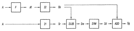
- FIG. 3 a is a diagram of the steps of the method for forming a global spectrum of an analogue signal according to a first implementation of the invention with two converters carrying out sampling in parallel;
- FIG. 3 b is a diagram of the steps of the method according to a second implementation of the invention with two converters carrying out alternated sampling;
- FIG. 3 c is a diagram of the steps of the method according to a third implementation of the invention with two converters processing analogue signals arising from two different analogue sensors;
- FIG. 3 d is a diagram of the steps of the method according to a fourth implementation of the invention for a signal of an operating parameter of a turboengine, the global spectrum being obtained on the basis of a base spectrum defined on the basis of a plurality of reference spectra.
- a fuel regulating parameter is an operating parameter of the turboengine.
- a rotor shaft In a conventional manner, a rotor shaft possesses a natural angular frequency which corresponds to its first torsional mode.
- the angular frequency depends on the geometry of the rotor shaft and is therefore known for the rotor shaft of the said turboengine.
- the phenomenon of resonance designated resonance subsequently, arises during excitation of the shaft of the rotor by an excitation signal whose frequency corresponds to the angular frequency of the shaft, this frequency of the excitation signal being designated resonant frequency. Stated otherwise, if the rotor shaft is excited by a signal at the resonant frequency, the rotor shaft resonates, thereby generating noise and fatigue of the rotor shaft.
- a fuel parameter varies in a slow manner globally, that is to say globally its frequency is less than 5 Hz, locally it can comprise fast frequencies, greater than 5 Hz, for example lying between 20 Hz and 50 Hz.
- These fast frequencies termed resonant frequencies or “fuel pulsing” must be measured so as to preclude any phenomenon of resonance of the rotor shaft and thus avoid the generation of noise in the cabin of the aircraft on which the turboengine is mounted or fatigue of the rotor shaft.
- the operating parameter in question is a fuel flow rate. It goes without saying that the fuel pressure or a degree of opening of a fuel intake flap could also be suitable.
- a turboengine resonance detection system comprises a digitization system comprising a computer designed to sample an analogue signal of a fuel parameter of the turboengine measured by a sensor of the turboengine.
- the computer possesses a sampling frequency Fe and a Shannon frequency Fs defined as half the sampling frequency Fe.
- the computer does not comprise any anti-aliasing filter.
- the computer possesses a sampling frequency Fe of 50 Hz and, consequently, a Shannon frequency Fs of 25 Hz.
- the resonant frequencies Fr are not visible but are aliased in the digital signal formed by the computer as represented in FIG. 1 c.
- the invention is therefore aimed at obtaining a global spectrum of the fuel parameter identical to that of FIG. 1 a , but with an existing computer whose sampling frequency is insufficient.
- the fuel flow rate parameter is measured first of all by means of a sensor of the turboengine to obtain an analogue signal A.
- This analogue signal is processed by a digitization system which comprises a first analogue-digital converter 21 and a second analogue-digital converter 22 .
- an aliasing spectrum Sr of the analogue signal A is formed, the analogue signal A not having been previously filtered by an anti-aliasing filter F. These steps correspond to the lower branch of the diagram of FIG. 3A .
- the aliasing spectrum Sr obtained corresponds to the spectrum of FIG. 1 c.
- the analogue signal A is filtered with an anti-aliasing filter F centred on the Shannon frequency of the first analogue-digital converter 21 to obtain a filtered analogue signal Af.
- the anti-aliasing filter F a low-pass filter for example, is centred with a cutoff frequency of 25 Hz and eliminates the signals whose frequency is greater than 25 Hz.
- the digitization system comprises, furthermore, a subtractor module SUB, designed to compute an aliased spectrum Sre by subtracting the base spectrum Sb from the aliasing spectrum Sr.
- the aliased spectrum Sre obtained corresponds to FIG. 1 d.
- a dealiased spectrum Sd is thereafter obtained through symmetry of the aliased spectrum Sre with respect to the Shannon frequency of the converters 21 , 22 .
- the digitization system comprises a symmetry module SYM designed to perform this symmetry.
- the dealiased spectrum Sd obtained corresponds to FIG. 1 e.
- a concatenation module ADD integrated into the digitization system, computes a global spectrum Sg by concatenating the dealiased spectrum Sd with or adding it to the base spectrum Sb.
- the global spectrum Sg obtained corresponds to FIG. 1 f.
- the signals whose frequency is greater than that of Fs in the aliased spectrum Sre have been measured.
- the said frequencies have been dealiased so as to complete the base spectrum Sb in order to form a global spectrum Sg.
- the global spectrum Sg obtained is advantageously similar to that which would have been obtained with an analogue-digital converter of higher sampling frequency.
- a doubled sampling frequency is simulated.
- FIG. 3B A second mode of implementation of the invention is described with reference to FIG. 3B .
- the references used to describe the elements of identical, equivalent or similar structure or function to those of the elements of FIG. 3A are the same, to simplify the description. Moreover, the whole of the description of the mode of implementation of FIG. 3A is not repeated, this description being applied to the elements of FIG. 3B when there are no incompatibilities. Only the appreciable, structural and functional differences are described.
- the digitization system comprises a switch COM designed to transmit the analogue signal A in an alternated manner:
- the analogue signal A is sliced into successive time windows, one time window out of two being filtered by the anti-aliasing filter F, all the time windows being thereafter digitized by the analogue-digital converters 21 , 22 .
- the successive time windows are all digitized by one and the same analogue-digital converter.
- the first window is filtered by the anti-aliasing filter and then digitized by the single converter.
- the second window is not filtered but digitized by the single converter.
- the third window is filtered by the anti-aliasing filter and then digitized by the single converter.
- one and the same analogue-digital converter alternately processes a filtered and unfiltered analogue signal.
- the number of arithmetic operations is therefore limited, contemporary converters with a single analogue input being suitable for implementing such steps.
- the duration of the time windows is computed in such a way that the variations of the analogue signal A between two successive time windows are negligible.
- the duration of the time window is of the order of 0.1 to 1 second.
- FIG. 3C A third mode of implementation of the invention is described with reference to FIG. 3C .
- the references used to describe the elements of identical, equivalent or similar structure or function to those of the elements of FIG. 3A are the same, to simplify the description. Moreover, the whole of the description of the mode of implementation of FIG. 3A is not repeated, this description being applied to the elements of FIG. 3C when there are no incompatibilities. Only the appreciable, structural and functional differences are described.
- the measurement of a fuel parameter is carried out with the aid of two distinct sensors (not represented) which measure respectively a first analogue signal A′ and a second analogue signal A′′.
- the relevance of this third embodiment is to do with the fact that the measured analogue signals are very similar to one another and represent one and the same measurement of a fuel parameter, here a fuel flow rate.
- the two analogue signals A′, A′′ are regarded as one and the same analogue signal A and the steps of the first embodiment such as represented in FIG. 3A are implemented.
- an aliasing spectrum Sr′′ of the first analogue signal A′′ is formed, the first analogue signal A′′ not having been previously filtered by an anti-aliasing filter F.
- the second analogue signal A′ is filtered with an anti-aliasing filter F to obtain a filtered analogue signal Af′.
- a base spectrum Sb′ is formed.
- the subtractor module SUB computes an aliased spectrum Sre by subtracting the aliasing spectrum Sr′′ from the base spectrum Sb′.
- the dealiased spectrum Sd is thereafter obtained through symmetry of the aliased spectrum Sre with respect to the Shannon frequency of the converters 21 , 22 .
- the concatenation module ADD computes a global spectrum Sg by concatenating the dealiased spectrum Sd with the base spectrum Sb′.
- the system can also comprise a switch COM which makes it possible alternately to dispatch the first filtered analogue signal Af′ and the second analogue signal A′′ to a single converter with a single analogue input in a similar manner to the second embodiment.
- a switch COM which makes it possible alternately to dispatch the first filtered analogue signal Af′ and the second analogue signal A′′ to a single converter with a single analogue input in a similar manner to the second embodiment.
- FIG. 3D A fourth mode of implementation of the invention is described with reference to FIG. 3D .
- the references used to describe the elements of identical, equivalent or similar structure or function to those of the elements of FIG. 3A are the same, to simplify the description. Moreover, the whole of the description of the mode of implementation of FIG. 3A is not repeated, this description being applied to the elements of FIG. 3D when there are no incompatibilities. Only the appreciable, structural and functional differences are described.
- the fuel flow rate parameter is measured first of all by means of a sensor of the turboengine to obtain an analogue signal A.
- an aliasing spectrum Sr of the analogue signal A is formed, the analogue signal A not having been previously filtered by an anti-aliasing filter F.
- the aliasing spectrum Sr corresponds to the spectrum that is obtained on contemporary computers which do not comprise any anti-aliasing filter.
- a subtractor module SUB integrated into the digitization system, computes an aliased spectrum Sre by subtracting a base spectrum Sb from the aliasing spectrum Sr.
- the base spectrum Sb is here a reference base spectrum Sb ref corresponding to a mean of several previously computed base spectra.
- the reference base spectrum Sbref is predetermined and does not need to be computed by the digitization system. Thus, it suffices solely to modify the existing computers in a software manner to obtain a global spectrum Sg, without adding an anti-aliasing filter.
- a known reference base spectrum Sb ref which is stored in the digitization system is available for each parameter of the engine.
- the reference base spectrum Sb ref corresponds to a mean of several base spectra computed previously for the said turboengine. Stated otherwise, an individual reference base spectrum has been computed for the said turboengine. This spectrum is subsequently designated individual spectrum.
- a plurality of base spectra is formed as indicated previously for several flight phases (startup, cruising, etc.) of a turboengine.
- an analogue signal measuring the parameter of the turboengine is filtered with an anti-aliasing filter to obtain a filtered analogue signal.
- an analogue-digital converter of Shannon frequency equal to that of the onboard converter, a base spectrum is formed.
- the mean of the base spectra is computed so as to form the individual spectrum.
- a filtering of the plurality of base spectra is carried out so as to delete the base spectra which are far removed from the other base spectra (variance computation, etc.).
- the plurality of base spectra is cleaned up so as to form a cleaned individual spectrum which is representative of the said turboengine.
- the global spectrum Sg is formed on the basis of a pre-computed individual spectrum so as to limit the computation steps in flight while having a made-to-measure global spectrum on account of the fact that the individual spectrum has been formed on the basis of measurements on the said turboengine.
- the reference base spectrum Sb ref corresponds to a mean of several individual spectra computed previously for several turboengines of one and the same family. Stated otherwise, a family reference base spectrum has been computed for the said family of turboengines. This spectrum is subsequently designated family spectrum.
- a plurality of individual spectra is formed as indicated previously for several flight phases (startup, cruising, etc.) of a family of turboengines.
- the mean of the individual spectra is computed so as to form the family spectrum.
- a filtering of the plurality of individual spectra is carried out so as to delete the individual spectra which are far removed from the other individual spectra (variance computation, etc.).
- the plurality of individual spectra is cleaned up so as to form a cleaned family spectrum which is representative of the operating parameter of the said family of turboengines.
- this makes it possible to dispense with forming an individual spectrum for each new engine. All the computations are carried out on the basis of a family spectrum computed previously for one and the same family of turboengines. This makes it possible to simplify the formation of a global spectrum for an operating parameter of a turboengine, doing so without modifying the existing computers.
- the invention has been presented here with a computer whose sampling frequency is 50 Hz but it goes without saying that the invention applies to a computer whose frequency is equal to 30 Hz or any other frequency.
Landscapes
- Physics & Mathematics (AREA)
- Engineering & Computer Science (AREA)
- General Physics & Mathematics (AREA)
- Theoretical Computer Science (AREA)
- Mathematical Physics (AREA)
- Chemical & Material Sciences (AREA)
- Combustion & Propulsion (AREA)
- Analogue/Digital Conversion (AREA)
- Measuring Frequencies, Analyzing Spectra (AREA)
- Testing Of Engines (AREA)
Abstract
-
- the analogue signal (A) is sampled with a first analogue-digital converter (21, 22) of determined Shannon frequency (Fs) so as to obtain an aliasing spectrum (Sr), the analogue signal (A) not having been previously filtered by an anti-aliasing filter;
- a base spectrum (Sb) is subtracted from the aliasing spectrum (Sr) so as to obtain an aliased spectrum (Sre), the base spectrum (Sb) corresponding to an aliasing-free spectrum of the said analogue signal;
- a dealiased spectrum (Sd) is computed on the basis of the aliased spectrum (Sre) as a function of the Shannon frequency (Fs) of the converter (21, 22);
- the base spectrum (Sb) is concatenated with the dealiased spectrum (Sde) so as to form the global spectrum (Sg) of the analogue signal (A).
Description
-
- the analogue signal is sampled with a first analogue-digital converter of determined Shannon frequency so as to obtain an aliasing spectrum, the analogue signal not having been previously filtered by an anti-aliasing filter;
- a base spectrum is subtracted from the aliasing spectrum so as to obtain an aliased spectrum, the base spectrum corresponding to an aliasing-free spectrum of the said analogue signal;
- a dealiased spectrum is computed on the basis of the aliased spectrum as a function of the Shannon frequency of the converter;
- the base spectrum is concatenated with the dealiased spectrum so as to form the global spectrum of the analogue signal.
-
- an anti-aliasing filter is applied to the said analogue signal at the Shannon frequency over a second time window;
- the said filtered analogue signal is sampled with a second analogue-digital converter of the same Shannon frequency so as to obtain the base spectrum.
-
- an anti-aliasing filter is applied to the said reference analogue signals at the Shannon frequency;
- the said reference analogue signals are sampled with a second analogue-digital converter of the same Shannon frequency as the first analogue-digital converter so as to obtain the reference spectra of the reference analogue signals;
- a mean of the reference spectra is computed so as to form the base spectrum.
-
- to the first analogue-
digital converter 21 so as to form an aliasing spectrum Sr of the analogue signal A, the analogue signal A not having been previously filtered by an anti-aliasing filter F; and - to the anti-aliasing filter F so as to obtain a filtered analogue signal, and then, to the second analogue-
digital converter 22 so as to form the base spectrum Sb.
- to the first analogue-
Claims (8)
Applications Claiming Priority (2)
| Application Number | Priority Date | Filing Date | Title |
|---|---|---|---|
| FR1051192 | 2010-02-18 | ||
| FR1051192A FR2956495B1 (en) | 2010-02-18 | 2010-02-18 | PROCESS FOR DIGITIZING AN ANALOGUE SIGNAL BY AN ANALOGUE-DIGITAL CONVERTER OF DETERMINED SHANNON FREQUENCY |
Publications (2)
| Publication Number | Publication Date |
|---|---|
| US20110199249A1 US20110199249A1 (en) | 2011-08-18 |
| US8350742B2 true US8350742B2 (en) | 2013-01-08 |
Family
ID=42740389
Family Applications (1)
| Application Number | Title | Priority Date | Filing Date |
|---|---|---|---|
| US13/030,546 Active 2031-06-25 US8350742B2 (en) | 2010-02-18 | 2011-02-18 | Method for digitizing an analogue signal with an analogue-digital converter of determined Shannon frequency |
Country Status (3)
| Country | Link |
|---|---|
| US (1) | US8350742B2 (en) |
| FR (1) | FR2956495B1 (en) |
| GB (1) | GB2478048B (en) |
Cited By (1)
| Publication number | Priority date | Publication date | Assignee | Title |
|---|---|---|---|---|
| US20110259093A1 (en) * | 2010-02-18 | 2011-10-27 | Snecma | Method for detecting resonance in a rotor shaft of a turbine engine |
Citations (3)
| Publication number | Priority date | Publication date | Assignee | Title |
|---|---|---|---|---|
| US6031879A (en) * | 1997-11-05 | 2000-02-29 | The United States Of America As Represented By The Secretary Of The Navy | Wideband undersampling digital receiver |
| US7304597B1 (en) * | 2006-05-26 | 2007-12-04 | Lecroy Corporation | Adaptive interpolation for use in reducing signal spurs |
| US20110173009A1 (en) * | 2008-07-11 | 2011-07-14 | Guillaume Fuchs | Apparatus and Method for Encoding/Decoding an Audio Signal Using an Aliasing Switch Scheme |
Family Cites Families (6)
| Publication number | Priority date | Publication date | Assignee | Title |
|---|---|---|---|---|
| IT1240168B (en) * | 1990-04-05 | 1993-11-27 | Marelli Autronica | ANALOG / DIGITAL CONVERSION SYSTEM WITH INCREASED RESOLUTION. |
| EP1032136A1 (en) * | 1999-02-25 | 2000-08-30 | Lucent Technologies Inc. | Nyquist band frequency translation |
| US7373119B2 (en) * | 2002-03-07 | 2008-05-13 | Telefonaktiebolaget Lm Ericsson (Publ) | Method and apparatus for analog-to-digital conversion |
| FR2892516B1 (en) * | 2005-10-21 | 2008-01-25 | Snecma Sa | METHOD AND SYSTEM FOR DETECTING AND MEASURING FREQUENCY DISTURBANCES OF THE ROTATION SPEED OF A ROTOR |
| US8687689B2 (en) * | 2005-10-25 | 2014-04-01 | William Marsh Rice University | Method and apparatus for on-line compressed sensing |
| US20100309317A1 (en) * | 2009-06-04 | 2010-12-09 | Wi-Lan Inc. | Device and method for detecting unused tv spectrum for wireless communication systems |
-
2010
- 2010-02-18 FR FR1051192A patent/FR2956495B1/en active Active
-
2011
- 2011-02-15 GB GB1102617.6A patent/GB2478048B/en active Active
- 2011-02-18 US US13/030,546 patent/US8350742B2/en active Active
Patent Citations (3)
| Publication number | Priority date | Publication date | Assignee | Title |
|---|---|---|---|---|
| US6031879A (en) * | 1997-11-05 | 2000-02-29 | The United States Of America As Represented By The Secretary Of The Navy | Wideband undersampling digital receiver |
| US7304597B1 (en) * | 2006-05-26 | 2007-12-04 | Lecroy Corporation | Adaptive interpolation for use in reducing signal spurs |
| US20110173009A1 (en) * | 2008-07-11 | 2011-07-14 | Guillaume Fuchs | Apparatus and Method for Encoding/Decoding an Audio Signal Using an Aliasing Switch Scheme |
Non-Patent Citations (4)
| Title |
|---|
| French Preliminary Search Report issued Nov. 5, 2010, in French 1051192, filed Feb. 18, 2010 (with English Translation of Category of Documents). |
| Pace et al., Use of the Symmetrical Number System in Resolving Single-Frequency Undersampling Aliases, IEEE Transactions on Signal Processing, vol. 45, No. 5, May 1997 pp. 1153-1160. * |
| Rachid et al., A Novel Reconfigurable Alias Interference Cancellation Technique for A-to-D Conversion, 2011 IEEE International Symposium on Circuits and Systems (ISCAS), Publication Year: 2011 , pp. 1656-1659 IEEE Conference Publications. * |
| Richard E. Leino, "Use of the Symmetrical Number System in Resolving Undersampling Aliases", Naval Postgraduate School, XP002603216, Sep. 1, 1996, 11 pages. |
Cited By (2)
| Publication number | Priority date | Publication date | Assignee | Title |
|---|---|---|---|---|
| US20110259093A1 (en) * | 2010-02-18 | 2011-10-27 | Snecma | Method for detecting resonance in a rotor shaft of a turbine engine |
| US8474307B2 (en) * | 2010-02-18 | 2013-07-02 | Snecma | Method for detecting resonance in a rotor shaft of a turbine engine |
Also Published As
| Publication number | Publication date |
|---|---|
| US20110199249A1 (en) | 2011-08-18 |
| FR2956495A1 (en) | 2011-08-19 |
| FR2956495B1 (en) | 2021-08-06 |
| GB2478048A (en) | 2011-08-24 |
| GB201102617D0 (en) | 2011-03-30 |
| GB2478048B (en) | 2017-05-03 |
Similar Documents
| Publication | Publication Date | Title |
|---|---|---|
| US7509862B2 (en) | System and method for providing vibration detection in turbomachinery | |
| US7761256B2 (en) | Method and system for use in analyzing vibrations of a variable speed rotating body | |
| CN107505135B (en) | A method and system for extracting composite faults of rolling bearings | |
| US9551629B2 (en) | System for acquiring a vibratory signal of a rotary motor | |
| JP3771195B2 (en) | Weight measuring noise removing device and weight measuring noise removing method | |
| EP3049788B1 (en) | Gear fault detection | |
| US7031873B2 (en) | Virtual RPM sensor | |
| US9016132B2 (en) | Rotating blade analysis | |
| CN102650658B (en) | Time-varying non-stable-signal time-frequency analyzing method | |
| EP1884746B1 (en) | Multiplexed signal conditioner | |
| US10281297B2 (en) | Blade tip timing | |
| CN112105907B (en) | Method and apparatus for monitoring a gear system | |
| CN113074941A (en) | Variable-speed gear fault signal extraction method, diagnosis method and system based on adaptive time-varying comb filtering and storage medium | |
| CN115496102A (en) | Wind turbine generator blade fault diagnosis method and device, equipment and storage medium | |
| JP5325266B2 (en) | Method and apparatus for measuring unbalance amount of rotating body | |
| US8350742B2 (en) | Method for digitizing an analogue signal with an analogue-digital converter of determined Shannon frequency | |
| JP4080602B2 (en) | Method for monitoring a vehicle with an acceleration sensor, in particular a helicopter transmission assembly | |
| US8860505B2 (en) | Lock-in amplifier with phase-synchronous processing | |
| CN100545615C (en) | Calculation method of work done by internal combustion engine | |
| JP6090000B2 (en) | Frequency analyzer | |
| ITTO970591A1 (en) | METHOD OF SURVEILLANCE OF A TRANSMISSION UNIT IN A VEHICLE EQUIPPED WITH ACCELEROMETRIC SENSORS, ESPECIALLY IN A HELICOPTER. | |
| Verma et al. | Denoising jet engine gas path measurements using nonlinear filters | |
| US20170254860A1 (en) | Method for ascertaining an internal resistance of an electrical energy accumulator | |
| CN112487574B (en) | Combustion stability margin assessment method | |
| CN114375387B (en) | Method for monitoring planetary gear trains by measuring the value of traveling mechanical waves |
Legal Events
| Date | Code | Title | Description |
|---|---|---|---|
| AS | Assignment |
Owner name: SNECMA, FRANCE Free format text: ASSIGNMENT OF ASSIGNORS INTEREST;ASSIGNORS:GEREZ, VALERIO;GRIFFATON, JULIEN CHRISTIAN PASCAL;REEL/FRAME:025835/0168 Effective date: 20110217 |
|
| STCF | Information on status: patent grant |
Free format text: PATENTED CASE |
|
| FPAY | Fee payment |
Year of fee payment: 4 |
|
| AS | Assignment |
Owner name: SAFRAN AIRCRAFT ENGINES, FRANCE Free format text: CHANGE OF NAME;ASSIGNOR:SNECMA;REEL/FRAME:046479/0807 Effective date: 20160803 |
|
| AS | Assignment |
Owner name: SAFRAN AIRCRAFT ENGINES, FRANCE Free format text: CORRECTIVE ASSIGNMENT TO CORRECT THE COVER SHEET TO REMOVE APPLICATION NOS. 10250419, 10786507, 10786409, 12416418, 12531115, 12996294, 12094637 12416422 PREVIOUSLY RECORDED ON REEL 046479 FRAME 0807. ASSIGNOR(S) HEREBY CONFIRMS THE CHANGE OF NAME;ASSIGNOR:SNECMA;REEL/FRAME:046939/0336 Effective date: 20160803 |
|
| MAFP | Maintenance fee payment |
Free format text: PAYMENT OF MAINTENANCE FEE, 8TH YEAR, LARGE ENTITY (ORIGINAL EVENT CODE: M1552); ENTITY STATUS OF PATENT OWNER: LARGE ENTITY Year of fee payment: 8 |
|
| MAFP | Maintenance fee payment |
Free format text: PAYMENT OF MAINTENANCE FEE, 12TH YEAR, LARGE ENTITY (ORIGINAL EVENT CODE: M1553); ENTITY STATUS OF PATENT OWNER: LARGE ENTITY Year of fee payment: 12 |