US8338988B2 - Adaptation of an active power supply set using an event trigger - Google Patents
Adaptation of an active power supply set using an event trigger Download PDFInfo
- Publication number
- US8338988B2 US8338988B2 US12/425,494 US42549409A US8338988B2 US 8338988 B2 US8338988 B2 US 8338988B2 US 42549409 A US42549409 A US 42549409A US 8338988 B2 US8338988 B2 US 8338988B2
- Authority
- US
- United States
- Prior art keywords
- mode
- power supply
- power
- active
- system load
- Prior art date
- Legal status (The legal status is an assumption and is not a legal conclusion. Google has not performed a legal analysis and makes no representation as to the accuracy of the status listed.)
- Expired - Fee Related, expires
Links
Images


Classifications
-
- G—PHYSICS
- G06—COMPUTING OR CALCULATING; COUNTING
- G06F—ELECTRIC DIGITAL DATA PROCESSING
- G06F1/00—Details not covered by groups G06F3/00 - G06F13/00 and G06F21/00
- G06F1/26—Power supply means, e.g. regulation thereof
- G06F1/32—Means for saving power
- G06F1/3203—Power management, i.e. event-based initiation of a power-saving mode
- G06F1/3206—Monitoring of events, devices or parameters that trigger a change in power modality
-
- H—ELECTRICITY
- H02—GENERATION; CONVERSION OR DISTRIBUTION OF ELECTRIC POWER
- H02J—CIRCUIT ARRANGEMENTS OR SYSTEMS FOR SUPPLYING OR DISTRIBUTING ELECTRIC POWER; SYSTEMS FOR STORING ELECTRIC ENERGY
- H02J3/00—Circuit arrangements for AC mains or AC distribution networks
- H02J3/12—Circuit arrangements for AC mains or AC distribution networks for adjusting voltage in AC networks by changing a characteristic of the network load
-
- G—PHYSICS
- G06—COMPUTING OR CALCULATING; COUNTING
- G06F—ELECTRIC DIGITAL DATA PROCESSING
- G06F1/00—Details not covered by groups G06F3/00 - G06F13/00 and G06F21/00
- G06F1/26—Power supply means, e.g. regulation thereof
- G06F1/263—Arrangements for using multiple switchable power supplies, e.g. battery and AC
-
- H—ELECTRICITY
- H02—GENERATION; CONVERSION OR DISTRIBUTION OF ELECTRIC POWER
- H02J—CIRCUIT ARRANGEMENTS OR SYSTEMS FOR SUPPLYING OR DISTRIBUTING ELECTRIC POWER; SYSTEMS FOR STORING ELECTRIC ENERGY
- H02J1/00—Circuit arrangements for DC mains or DC distribution networks
- H02J1/14—Balancing the load in a network
Definitions
- This disclosure relates generally to electrical technology, and more particularly to adaptation of an active power supply set using an event trigger.
- a redundant power supply system may provide power for a range of system loads, including a lower threshold power level and an upper threshold power level.
- the redundant power supply system may distribute the load across one or multiple power supplies that make up the redundant power supply system.
- the distribution of the load may result in a use of one or more power supplies below its rated power output, which may result in an inefficient generation of power.
- the inefficient generation of power may fail to meet an environmental standard, may consume excess resources, and may result in an additional cost of power.
- a method and systems of adaptation of an active power supply set using an event trigger are disclosed.
- a method in an exemplary embodiment, includes providing power to a system load using an active power supply set.
- the active power supply set includes a power supply in an active mode.
- the method further includes detecting an event trigger and increasing a power mode of an additional power supply when the event trigger is detected.
- An exemplary embodiment includes a power supply system.
- the power supply system includes an active power supply set to provide power to a system load.
- the active power supply set is comprised of a power supply in an active mode.
- the system includes an observation module to detect an event trigger.
- the system also includes an additional power supply.
- the system further includes a power control module to increase a power mode of the additional power supply when the event trigger is detected.
- a method in an exemplary embodiment includes providing power to a system load using an active power supply set.
- the active power supply set includes a power supply in an active mode.
- a utilization of the active power supply set is increased by operating an additional power supply in a lower power mode.
- the method further includes detecting an event trigger that includes an increased system load that exceeds a combined power capacity of the active power supply set by an upper threshold limit.
- the combined power capacity includes a sum of a power rating of each unit of the active power supply set.
- the method also includes increasing a power mode of the additional power supply to the active mode when the event trigger is detected.
- the method also incorporates including the additional power supply in the active power supply set.
- the method further includes utilizing the power supply of the active power supply set within a threshold tolerance range of a rating of the power supply when the power mode of the additional power supply is increased.
- the method includes detecting an additional event trigger comprised of a decreased system load that falls below a lower threshold limit that is supportable by one less than a number of power supply units in the active power supply set.
- the method further includes decreasing a power mode of a unit of the active power supply set when the additional event trigger is detected.
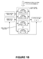
- FIGS. 1A and 1B are system views illustrating increasing a power mode of an additional power supply when the event trigger is detected, according to one embodiment.
- FIGS. 2A and 2B are system views illustrating decreasing a power mode of a unit of the active power supply set when an additional event trigger is detected, according to one embodiment.
- FIG. 3 is a graphical view illustrating power provided using multiple modes in response to a system load power level, according to one embodiment.
- FIG. 4 is a table view illustrating power supply states in different modes, according to one embodiment.
- FIG. 5 is a graphical representation illustrating different modes, associated system load levels, and a hysteresis window, according to one embodiment.
- FIG. 6 is a process flow that illustrates increasing and decreasing a power mode, according to one embodiment.
- FIG. 7 is a process flow illustrating management of power supplies, according to one embodiment.
- a method and systems of adaptation of an active power supply set using an event trigger are disclosed.
- FIGS. 1A and 1B are system views illustrating increasing a power mode of an additional power supply when the event trigger is detected, according to one embodiment.
- FIGS. 1A and 1B illustrate a power supply 100 A-N, a system load 102 , an observation module 104 , a power control module 105 , an event trigger data 106 and an active power supply set 108 , according to one embodiment.
- the observation module 104 may be coupled to the power supply 100 A-N and the system load 102 .
- the power control module 105 may be coupled to the power supply 100 A-N.
- the power supply 100 A-N may be coupled to each other and to the system load 102 .
- An active power supply set 108 may include one or more of the power supply 100 A-N that is in an active mode, which may be substantially equivalent to an on mode.
- the power supplies 100 A-N may be coupled in parallel.
- the power supplies 100 A-N may be sources of current and voltage for the system load 102 . Each power supply 100 A-N may be operated in one of several states, including: on, watch, sleep, and off. Each power supply 100 A-N may be utilized between 0% and 100% of its rated power capacity. The power supply 100 A-N may be used in excess of 100% of its rated power capacity, which may depend on a design tolerance of a manufacturer of the power supply.
- the power supply 100 A-N is an electronic device that generally increases in efficiency as its power generation approaches its power rating and decreases in efficiency when it generates power substantially below its power rating.
- the power supply 100 A-N is an electronic device that decreases in efficiency as it increases its power generation substantially above its power rating.
- each power supply 100 A-N that is part of the active power supply set 108 provides power to the system load 102 .
- the power supply 100 A-N of the active power supply set 108 may provide power between 0% and 100% of its rated capacity. In the embodiment, as the number of power supplies 100 A-N that provide power substantially at 100% is increased, the efficiency of the power generation by the power supply system is increased.
- the system load 102 may be the power utilized by one or more pieces of hardware, such as servers, fans, hard drives, processors, displays, cameras, and other devices.
- the system load 102 may increase or decrease over time, and the power utilized may be represented by the variable ⁇ .
- the power utilized by the system load 102 may vary between ⁇ and ⁇ , and the transition from FIG. 1A to FIG. 1B may represent an increase in power utilized by the system load 102 from ⁇ and ⁇ 110 .
- the power supply 100 A may be part of an active power supply set 108 .
- the power supply 100 A may have an active state, and it may supply power to the system load 102 between a lower system load and a threshold system load that utilizes the rated output of the power supply 100 A. Any additional system load may be powered by the additional power supply 100 B. The level of an additional system load may be sensed by the observation module 104 .
- the observation module 104 may include sensor circuitry, switches, relays, and other devices that enable the observation module 104 to detect an event trigger.
- the event trigger data 106 may include a change in the system load 102 state, such as from ⁇ to ⁇ .
- the event trigger data 106 may include the states of the power supply 100 A-N or the level of utilization of the power supply's 100 A-N rated output.
- the power control module 105 may include sensor circuitry, switches, relays, and other devices that enable the power control module 105 to increase a power mode of the additional power supply when the event trigger is detected.
- the power control module 105 may decrease the power mode of a unit of the active power supply set when the additional event trigger is detected.
- the power control module 105 may be hardware or software, and may be internal or external to each of the power supplies 100 A-N.
- the system load 102 level may be ⁇ .
- the power supply 100 A may be in an active state providing 58% of its rated power output to the system load 102 .
- the observation module 104 may receive an event trigger data 106 , which may include the change in the system load 102 from ⁇ to ⁇ .
- the event trigger data 106 may include the state of the power supply 100 A-N and the current power output level for each of the power supplies 100 A-N.
- the event trigger may be an increased system load 102 that exceeds a threshold limit, which may be substantially equivalent to a combined power capacity of substantially all units of the active power supply set.
- the state of the power supply 100 A may remain active, and its power output may increase from 58% to 100% of its rated power capacity.
- the power supply 100 A may provide power more efficiently at 100% of its rated power capacity than at 58%.
- the state of the power supply 100 B may increase from a watch mode to an active mode, and it may provide power to the system load 102 , which may be at a level ⁇ .
- the utilization of the power supply 100 B may increase from 0% to 34% of its rated power output.
- the state of the power supply 100 C may be changed from a sleep mode to a watch mode.
- the state of the power supply 100 N may remain in an off mode.
- the watch mode may enable a power supply 100 A-N to transition to an active mode in which it provides power to the system load.
- the watch mode may be higher than a sleep mode, which may in turn be higher than an off mode.
- the watch mode may consume less power than the active mode and more power than the sleep mode.
- the sleep mode may consume more power than the off mode.
- the time to transition between a watch mode and an active mode may be less than the time needed to transition between a sleep and a watch mode.
- the time used to transition between a sleep mode and an off mode may be greater than the time used to transition between a sleep mode and a watch mode.
- the time required to transition between each of the modes may vary, and a power supply may be capable of transitioning from any one mode directly to another mode. Additional information regarding power supply modes may be illustrated in FIG. 4 .
- Raising a state of a power supply 100 A-N may enable it to power the system load 102 .
- Lowering a state of a power supply 100 A-N may disable it, which may conserve energy.
- Enabling or disabling the power supplies 100 A-N may occur sequentially or simultaneously.
- the outputs of the power supplies may be an ORed output, which may be coupled to the system load 102 .
- the transition between the parallel power supplies may take place linearly, abruptly, and dynamically.
- the utilization of the power supply of the active power supply set 108 may be within a threshold tolerance range of a rating of the power supply 100 A-N when the power mode of the additional power supply is increased.
- the power supply 100 A may provide power within 25% of its rated output when one or more of the power supplies 100 B-N are increased in power mode.
- the utilization of the active power supply set 108 may be increased by operating an additional power supply in a lower power mode. For example, the utilization of the power supply 100 A may be 100% of its rated output while the output of the power supply 100 B is 34%.
- FIGS. 2A and 2B are system views illustrating decreasing a power mode of a unit of the active power supply set 108 when the additional event trigger is detected, according to one embodiment.
- FIG. 2A and FIG. 2B illustrate the power supply 100 A-N, the system load 102 , the observation module 104 , the event trigger data 106 , the active power supply set 108 , and decreasing system load 102 from ⁇ to ⁇ 112 , according to one embodiment.
- FIG. 2 illustrates an instance when the system load 102 is decreased from ⁇ to ⁇ .
- the system load 102 ⁇ may use the power supply 100 A- 100 C.
- the active power supply set 108 may include the power supply 100 A, the power supply 100 B, and the power supply 100 C.
- the power supplies 100 A-B may operate in full operating condition, which may be 100% of the rated power supply output.
- the power supply 100 C may provide the remaining 20% to meet the level of the system load 102 ⁇ .
- a remaining power supply 100 D may be in watch mode, prepared to operate when useful.
- the system load 102 ⁇ may come down to the lower system load level ⁇ , which may be included in an event trigger data 106 .
- the observation module 104 upon sensing event trigger data 106 , may switch the power supply 100 C to the watch mode and reduce its power output to 0% of its rated output capacity.
- the power supply 100 B may be in an active mode, and it may provide 68% of its rated output. The remaining power supplies may be put into sleep or inactive modes.
- FIG. 3 is a graphical view illustrating power provided using multiple modes in response to a system load power level, according to one embodiment.
- FIG. 3 illustrates power 312 , the system load power level 314 , Mode I 316 , Mode II 318 , Mode III 320 , Mode IV 322 , and a hysteresis window 324 , according to one embodiment.
- the modes described are for four power supply units. The same concept may be used for a system having ‘N’ number of power supply units.
- the truth table for different modes in which the power supplies 100 A-N of FIG. 3 may be operated is illustrated in FIG. 4 .
- fewer modes may be used.
- an embodiment may use an active, watch, and off mode.
- an embodiment may use only an active mode and a lower power mode, which may be watch, sleep, or off.
- the active mode may be substantially the same as the on mode described with respect to FIG. 4 .
- Mode I 316 may be used to provide power between 0% and 25% of the system load level.
- Mode II 318 may be used to provide power from 25% to 50% of the system power level, and
- Mode III 320 may be used to provide power from 50% to 75% of the system load power level.
- Mode IV 322 may be used to provide power from 75% to 100% of the system load power level.
- any system load power level 314 threshold may be used between various modes, depending on the power capability of each mode and a desired hysteresis window size.
- transitions between Mode I 316 and Mode II 318 may occur at approximately 25% of the system load level 314 . Transitions between Mode II 318 and Mode III 320 may occur at 50%, and transitions between Mode III 320 and Mode IV 322 may occur at 75% of the system load level 314 .
- transitions between Mode I 316 and Mode II 318 may occur at approximately 20% of the system load power level 314 .
- Transitions between Mode II 318 and Mode III 320 may occur at 45%, and transitions between Mode III 320 and Mode IV 322 may occur at 70% of the system load power level 314 .
- a hysteresis window 324 may exist between 20% and 25%, between 45% and 50%, and between 70% and 75% of the system load power level 314 .
- the upper level of the hysteresis window 324 may represent an upper threshold limit at which a rated power output of the power supply 100 A-N that are active in the mode has been met.
- the upper threshold limit may be substantially equivalent to a combined power capacity of substantially all units of the active power supply set 108 .
- the lower level of the hysteresis window 324 may represent a lower threshold limit in which the system load power level 314 is supportable by one less than a number of power supply units in the active power supply set 108 .
- the lower threshold limit may represent a power level where one of the power supply 100 A-N may be removed from the active power supply set 108 while still providing sufficient power to supply the system load power level 314 .
- the hysteresis window 324 may enable a system load power level 314 to fluctuate between an upper and a lower threshold without triggering a change in modes. For instance, a first mode may provide power for the system load power 314 until an upper threshold limit is reached, at which point a second mode may be activated to provide additional power to the system load power level 314 . The second mode may continue to provide power to the system load power level 314 until the lower threshold limit of the hysteresis window 324 is reached.
- the lower threshold limit of the hysteresis window 324 may be lower than the upper threshold limit of the hysteresis window 324 .
- the hysteresis window may be better understood from FIG. 5 .
- FIG. 4 is a table view illustrating power supply states in different modes, according to one embodiment.
- FIG. 4 illustrates mode and power supply fields, according to one embodiment.
- FIG. 4 may illustrate a truth table for the graphical view illustrated in FIG. 3 .
- Mode I 316 the power supply 100 A may be on, the power supply 100 B may be in a watch mode, the power supply 100 C may be in a sleep mode, and the power supply 100 D may be off.
- Mode II 318 the power supply 100 A may be on, the power supply 100 B may be on, the power supply 100 C may be in a watch mode, and the power supply 100 D may be in a sleep mode.
- Mode III 320 the power supply 100 A, the power supply 100 B, and the power supply 100 C may be on, and the power supply 100 D may be in a watch mode.
- Mode IV 322 all the power supplies 100 A-D may be on.
- FIG. 5 is a graphical representation illustrating different modes, associated system load levels, and the hysteresis window, according to one embodiment.
- FIG. 5 illustrates Mode I 316 , Mode II 318 , mode III 320 , Mode IV 322 , upper threshold limit 526 , and lower threshold limit 528 .
- FIG. 3 and FIG. 4 illustrated mode changes based on the system load 102 levels.
- the lower threshold limit 528 may be 20%, 45%, and 70% of the system load power level 314 .
- the upper threshold limit 526 may be 25%, 50%, and 75% of the system load power level 314 .
- transitions between Mode I 316 and Mode II 318 may occur at approximately 25% of the system load level 314 . Transitions between Mode II 318 and Mode III 320 may occur at 50%, and transitions between Mode III 320 and Mode IV 322 may occur at 75% of the system load level 314 . As the system load power level 314 decreases, transitions between Mode I 316 and Mode II 318 may occur at approximately 20% of the system load level 314 . Transitions between Mode II 318 and Mode III 320 may occur at 45%, and transitions between Mode III 320 and Mode IV 322 may occur at 70% of the system load level 314 .
- the mode levels of the power supply system may dynamically and automatically change in accordance with the upper threshold limits 526 and the lower threshold limits 528 .
- the mode transition may be linear and in sequence.
- FIG. 6 is a process flow that illustrates increasing and decreasing a power mode, according to one embodiment.
- power may be provided to the system load 102 using an active power supply set 108 .
- the active power supply set 108 may include power supplies in an active mode (e.g., as illustrated in FIGS. 1 and 2 ).
- an event trigger may be detected.
- the event trigger may be detected using the event trigger data 106 that is analyzed by the observation module 104 .
- a power mode of the additional power supply 10 B-N may be increased when the event trigger is detected (e.g., as illustrated in FIG. 1 ).
- an additional event trigger may be detected.
- a power mode of a unit of the active power supply set 108 may be decreased when the additional event trigger is detected (e.g., as illustrated in FIG. 2 ).
- FIG. 7 is a process flow illustrating management of power supplies, according to one embodiment.
- power may be provided to the system load 102 using the active power supply set 108 .
- the active power supply set 108 may include one or more of power supplies in the active mode.
- the active mode may be substantially the same as the on mode illustrated in FIG. 4 .
- the utilization of the active power supply set 108 may be increased by operating an additional power supply in a lower power mode.
- an event trigger may be detected that includes an increased system load 102 that exceeds a combined power capacity of the active power supply set 108 by the upper threshold limit 526 .
- the combined power capacity may be a sum of a power rating of each unit of the active power supply set 108 .
- a power mode of the additional power supply 100 B may be increased to the active mode when the event trigger is detected.
- the additional power supply 100 B may be included in the active power supply set 108 .
- the power supply of the active power supply set 108 may be utilized within a threshold tolerance range of a rating of the power supply when the power mode of the additional power supply is increased.
- an additional event trigger that includes a decreased system load may be detected that falls below the lower threshold limit 528 that is supportable by one less than a number of power supply units in the active power supply set 108 .
- a power mode of a unit of the active power supply set 108 may be decreased when the additional event trigger is detected.
- the various devices, modules, analyzers, generators, etc. described herein may be enabled and operated using hardware circuitry (e.g., CMOS based logic circuitry), firmware, software and/or any combination of hardware, firmware, and/or software (e.g., embodied in a machine readable medium).
- hardware circuitry e.g., CMOS based logic circuitry
- firmware e.g., software and/or any combination of hardware, firmware, and/or software (e.g., embodied in a machine readable medium).
- the various electrical structure and methods may be embodied using transistors, logic gates, and electrical circuits (e.g., application specific integrated (ASIC) circuitry and/or in Digital Signal Processor (DSP) circuitry).
- ASIC application specific integrated
- DSP Digital Signal Processor
- observation module 104 and the power control module 105 may be enabled using software and/or using transistors, logic gates, and electrical circuits (e.g., application specific integrated ASIC circuitry) such an observation circuit, sensor circuit, switches and other circuits.
- electrical circuits e.g., application specific integrated ASIC circuitry
Landscapes
- Engineering & Computer Science (AREA)
- Theoretical Computer Science (AREA)
- Power Engineering (AREA)
- Physics & Mathematics (AREA)
- General Engineering & Computer Science (AREA)
- General Physics & Mathematics (AREA)
- Supply And Distribution Of Alternating Current (AREA)
- Direct Current Feeding And Distribution (AREA)
- Power Sources (AREA)
- Remote Monitoring And Control Of Power-Distribution Networks (AREA)
Abstract
Description
Claims (20)
Priority Applications (7)
| Application Number | Priority Date | Filing Date | Title |
|---|---|---|---|
| US12/425,494 US8338988B2 (en) | 2009-04-17 | 2009-04-17 | Adaptation of an active power supply set using an event trigger |
| KR1020117013989A KR20120006479A (en) | 2009-04-17 | 2009-05-05 | Adaptation of Active Power Supply Sets Using Event Triggers |
| CN200980155732.5A CN102301555B (en) | 2009-04-17 | 2009-05-05 | Running Power Groups with Event-Triggered Debugging |
| PCT/US2009/042759 WO2010120316A1 (en) | 2009-04-17 | 2009-05-05 | Adaptation of an active power supply set using an event trigger |
| JP2012505869A JP5351331B2 (en) | 2009-04-17 | 2009-05-05 | Adapting active power sets using event triggers |
| EP09843466A EP2419982A1 (en) | 2009-04-17 | 2009-05-05 | Adaptation of an active power supply set using an event trigger |
| TW98128538A TW201039116A (en) | 2009-04-17 | 2009-08-25 | Adaptation of an active power supply set using an event trigger |
Applications Claiming Priority (1)
| Application Number | Priority Date | Filing Date | Title |
|---|---|---|---|
| US12/425,494 US8338988B2 (en) | 2009-04-17 | 2009-04-17 | Adaptation of an active power supply set using an event trigger |
Publications (2)
| Publication Number | Publication Date |
|---|---|
| US20100264741A1 US20100264741A1 (en) | 2010-10-21 |
| US8338988B2 true US8338988B2 (en) | 2012-12-25 |
Family
ID=42980462
Family Applications (1)
| Application Number | Title | Priority Date | Filing Date |
|---|---|---|---|
| US12/425,494 Expired - Fee Related US8338988B2 (en) | 2009-04-17 | 2009-04-17 | Adaptation of an active power supply set using an event trigger |
Country Status (7)
| Country | Link |
|---|---|
| US (1) | US8338988B2 (en) |
| EP (1) | EP2419982A1 (en) |
| JP (1) | JP5351331B2 (en) |
| KR (1) | KR20120006479A (en) |
| CN (1) | CN102301555B (en) |
| TW (1) | TW201039116A (en) |
| WO (1) | WO2010120316A1 (en) |
Cited By (3)
| Publication number | Priority date | Publication date | Assignee | Title |
|---|---|---|---|---|
| US20140245035A1 (en) * | 2010-12-27 | 2014-08-28 | Juniper Networks, Inc. | N+1 power supply system upgrade using dual output power supplies |
| US20140258739A1 (en) * | 2013-03-11 | 2014-09-11 | Don Gunasekara | Adaptive power control in a network |
| US20170170683A1 (en) * | 2015-12-15 | 2017-06-15 | Eaton Corporation | Data center power systems with dynamic source designation |
Families Citing this family (31)
| Publication number | Priority date | Publication date | Assignee | Title |
|---|---|---|---|---|
| US8312300B2 (en) * | 2009-07-31 | 2012-11-13 | Hewlett-Packard Development Company, L.P. | Limiting power in redundant power supply systems |
| US8276000B2 (en) * | 2009-10-28 | 2012-09-25 | Hewlett-Packard Development Company, L.P. | System and method for supplying power to a load using deep-sleep-mode power supplies |
| CN102129284B (en) * | 2010-01-18 | 2013-11-06 | 华为技术有限公司 | Method, device and system for reducing power consumption of business system |
| JP5636267B2 (en) * | 2010-11-19 | 2014-12-03 | 中国電力株式会社 | DC power supply device, electric vehicle charging device, DC power supply unit parallel operation method, and electric vehicle charging current control method |
| US20120205976A1 (en) * | 2011-02-10 | 2012-08-16 | Tsun-Te Shih | Redundant power system regulating operation according to loads |
| US8668170B2 (en) * | 2011-06-27 | 2014-03-11 | Thales Canada Inc. | Railway signaling system with redundant controllers |
| WO2013097241A1 (en) * | 2011-12-31 | 2013-07-04 | 华为技术有限公司 | Method and device for processing when power is supplied by multiple sources |
| US8949645B2 (en) * | 2012-01-24 | 2015-02-03 | Nvidia Corporation | Power distribution for microprocessor power gates |
| US20130293210A1 (en) * | 2012-05-07 | 2013-11-07 | Apple Inc. | Coupled voltage converters |
| WO2015066048A1 (en) * | 2013-10-28 | 2015-05-07 | Virtual Power Systems, Inc. | Energy control via power requirement analysis and power source enablement |
| US11126242B2 (en) | 2013-10-28 | 2021-09-21 | Virtual Power Systems, Inc. | Time varying power management within datacenters |
| US10429914B2 (en) | 2013-10-28 | 2019-10-01 | Virtual Power Systems, Inc. | Multi-level data center using consolidated power control |
| US10747289B2 (en) | 2013-10-28 | 2020-08-18 | Virtual Power Systems, Inc. | Data center power manipulation |
| CN104765294A (en) * | 2015-03-20 | 2015-07-08 | 深圳欧陆通电子有限公司 | Power supply system and method, for reducing consumption intelligently, of system |
| US10095254B2 (en) * | 2015-03-25 | 2018-10-09 | Cisco Technology, Inc. | Power distribution management |
| JP6660553B2 (en) * | 2015-11-30 | 2020-03-11 | パナソニックIpマネジメント株式会社 | POWER SUPPLY, POWER SUPPLY CONTROL METHOD, AND POWER SUPPLY CONTROL PROGRAM |
| US11455021B2 (en) | 2016-08-18 | 2022-09-27 | Cato | Datacenter power management using AC and DC power sources |
| US10585468B2 (en) | 2016-08-18 | 2020-03-10 | Virtual Power Systems, Inc. | Datacenter power management using dynamic redundancy |
| US11461513B2 (en) | 2016-08-18 | 2022-10-04 | Cato | Data center power scenario simulation |
| US11107016B2 (en) | 2016-08-18 | 2021-08-31 | Virtual Power Systems, Inc. | Augmented power control within a datacenter using predictive modeling |
| JP6469628B2 (en) * | 2016-11-07 | 2019-02-13 | 東京瓦斯株式会社 | UNIT CONTROL DEVICE, UNIT CONTROL METHOD, AND PROGRAM |
| JP6828507B2 (en) * | 2017-02-24 | 2021-02-10 | コニカミノルタ株式会社 | Information processing equipment and programs |
| US10969846B2 (en) | 2017-05-25 | 2021-04-06 | Virtual Power Systems, Inc. | Secure communication initiation and execution for datacenter power control |
| JP6922449B2 (en) * | 2017-06-08 | 2021-08-18 | 富士電機株式会社 | Power system and power supply |
| WO2019005023A1 (en) * | 2017-06-28 | 2019-01-03 | Halliburton Energy Services, Inc. | Redundant power source for increased reliability in a permanent completion |
| US11500439B2 (en) | 2018-03-02 | 2022-11-15 | Samsung Electronics Co., Ltd. | Method and apparatus for performing power analytics of a storage system |
| US11481016B2 (en) | 2018-03-02 | 2022-10-25 | Samsung Electronics Co., Ltd. | Method and apparatus for self-regulating power usage and power consumption in ethernet SSD storage systems |
| US11216059B2 (en) | 2018-03-05 | 2022-01-04 | Virtual Power Systems, Inc. | Dynamic tiering of datacenter power for workloads |
| EP3829017A1 (en) * | 2019-11-27 | 2021-06-02 | Wobben Properties GmbH | Method for providing a requested power |
| TW202522174A (en) * | 2023-11-17 | 2025-06-01 | 緯穎科技服務股份有限公司 | Server system and power management method thereof |
| US20250341876A1 (en) * | 2024-05-01 | 2025-11-06 | International Business Machines Corporation | Power supply configuration based power capping |
Citations (20)
| Publication number | Priority date | Publication date | Assignee | Title |
|---|---|---|---|---|
| US5892299A (en) * | 1996-09-24 | 1999-04-06 | Siewert; James Carl | Simultaneous power supply source |
| US5939799A (en) * | 1997-07-16 | 1999-08-17 | Storage Technology Corporation | Uninterruptible power supply with an automatic transfer switch |
| US6018204A (en) * | 1997-01-16 | 2000-01-25 | Nec Corporation | Power supply system |
| US20020130712A1 (en) * | 2001-03-16 | 2002-09-19 | Naffziger Samuel D. | System and method utilizing on-chip voltage monitoring to manage power consumption |
| US20030056125A1 (en) * | 2001-09-19 | 2003-03-20 | Dell Products L.P. | System and method for strategic power supply sequencing in a computer system |
| US6654264B2 (en) * | 2000-12-13 | 2003-11-25 | Intel Corporation | System for providing a regulated voltage with high current capability and low quiescent current |
| US6735704B1 (en) * | 2000-10-20 | 2004-05-11 | International Business Machines Corporation | Autonomic control of power subsystems in a redundant power system |
| US20050215227A1 (en) * | 2004-03-23 | 2005-09-29 | Vu Mieu V | Method and apparatus for entering a low power mode |
| US20050280312A1 (en) * | 2004-06-18 | 2005-12-22 | Bose Corporation | Controlling a power converter |
| US20060290327A1 (en) * | 2005-06-23 | 2006-12-28 | Samsung Electronics Co., Ltd. | Electronic device and electronic device system |
| US20070150763A1 (en) * | 2005-12-08 | 2007-06-28 | Yil Suk Yang | Highly energy-efficient processor employing dynamic voltage scaling |
| US20070216229A1 (en) * | 2006-03-17 | 2007-09-20 | Johnson Robert W Jr | UPS methods, systems and computer program products providing adaptive availability |
| US20080009248A1 (en) * | 2006-07-10 | 2008-01-10 | Dmitriy Rozenblit | Polar transmitter having a dynamically controlled voltage regulator and method for operating same |
| US20080122518A1 (en) * | 2006-11-27 | 2008-05-29 | Besser David A | Multi-Source, Multi-Load Systems with a Power Extractor |
| US20080172565A1 (en) * | 2007-01-12 | 2008-07-17 | Asustek Computer Inc. | Multi-processor system and performance adjustment method thereof |
| US20090158070A1 (en) * | 2007-12-13 | 2009-06-18 | International Business Machines Corporation | Selecting Between High Availability Redundant Power Supply Modes For Powering A Computer System |
| US20090174262A1 (en) * | 2008-01-04 | 2009-07-09 | Martin Gary D | Power supply and controller circuits |
| US20100077238A1 (en) * | 2008-09-25 | 2010-03-25 | Wisconsin Alumni Research Foundation | Energy efficienct power supply system |
| US7906871B2 (en) * | 2008-12-30 | 2011-03-15 | International Business Machines Corporation | Apparatus, system, and method for reducing power consumption on devices with multiple power supplies |
| US7962769B1 (en) * | 2007-04-30 | 2011-06-14 | Hewlett-Packard Development Company, L.P. | Balancing of renewable power usage and workload performance between cooling system and electronic components |
Family Cites Families (7)
| Publication number | Priority date | Publication date | Assignee | Title |
|---|---|---|---|---|
| DE3534979A1 (en) * | 1985-07-25 | 1987-01-29 | Licentia Gmbh | POWER SUPPLY |
| US6864600B2 (en) * | 2001-02-09 | 2005-03-08 | National Semiconductor Corporation | Apparatus and method for providing multiple power supply voltages to an integrated circuit |
| US6614133B2 (en) * | 2001-10-31 | 2003-09-02 | Hewlett-Packard Development Company, L.P. | Power system with plural parallel power supplies with at least one power supply in standby mode for energy efficiency |
| CN2601477Y (en) * | 2002-11-05 | 2004-01-28 | 北京曙光天演信息技术有限公司 | A hot-swappable multi-channel switching power supply module parallel power supply balanced power supply device |
| JP4038134B2 (en) * | 2003-02-05 | 2008-01-23 | インターナショナル・ビジネス・マシーンズ・コーポレーション | Power supply control apparatus and information processing apparatus |
| US20070204183A1 (en) * | 2006-02-24 | 2007-08-30 | Zippy Technology Corp. | Method and apparatus for processing abnormal conditions of a backup-type power supply system |
| JP2009060758A (en) * | 2007-09-03 | 2009-03-19 | Alaxala Networks Corp | Electronic equipment |
-
2009
- 2009-04-17 US US12/425,494 patent/US8338988B2/en not_active Expired - Fee Related
- 2009-05-05 CN CN200980155732.5A patent/CN102301555B/en not_active Expired - Fee Related
- 2009-05-05 KR KR1020117013989A patent/KR20120006479A/en not_active Ceased
- 2009-05-05 EP EP09843466A patent/EP2419982A1/en not_active Withdrawn
- 2009-05-05 WO PCT/US2009/042759 patent/WO2010120316A1/en not_active Ceased
- 2009-05-05 JP JP2012505869A patent/JP5351331B2/en not_active Expired - Fee Related
- 2009-08-25 TW TW98128538A patent/TW201039116A/en unknown
Patent Citations (20)
| Publication number | Priority date | Publication date | Assignee | Title |
|---|---|---|---|---|
| US5892299A (en) * | 1996-09-24 | 1999-04-06 | Siewert; James Carl | Simultaneous power supply source |
| US6018204A (en) * | 1997-01-16 | 2000-01-25 | Nec Corporation | Power supply system |
| US5939799A (en) * | 1997-07-16 | 1999-08-17 | Storage Technology Corporation | Uninterruptible power supply with an automatic transfer switch |
| US6735704B1 (en) * | 2000-10-20 | 2004-05-11 | International Business Machines Corporation | Autonomic control of power subsystems in a redundant power system |
| US6654264B2 (en) * | 2000-12-13 | 2003-11-25 | Intel Corporation | System for providing a regulated voltage with high current capability and low quiescent current |
| US20020130712A1 (en) * | 2001-03-16 | 2002-09-19 | Naffziger Samuel D. | System and method utilizing on-chip voltage monitoring to manage power consumption |
| US20030056125A1 (en) * | 2001-09-19 | 2003-03-20 | Dell Products L.P. | System and method for strategic power supply sequencing in a computer system |
| US20050215227A1 (en) * | 2004-03-23 | 2005-09-29 | Vu Mieu V | Method and apparatus for entering a low power mode |
| US20050280312A1 (en) * | 2004-06-18 | 2005-12-22 | Bose Corporation | Controlling a power converter |
| US20060290327A1 (en) * | 2005-06-23 | 2006-12-28 | Samsung Electronics Co., Ltd. | Electronic device and electronic device system |
| US20070150763A1 (en) * | 2005-12-08 | 2007-06-28 | Yil Suk Yang | Highly energy-efficient processor employing dynamic voltage scaling |
| US20070216229A1 (en) * | 2006-03-17 | 2007-09-20 | Johnson Robert W Jr | UPS methods, systems and computer program products providing adaptive availability |
| US20080009248A1 (en) * | 2006-07-10 | 2008-01-10 | Dmitriy Rozenblit | Polar transmitter having a dynamically controlled voltage regulator and method for operating same |
| US20080122518A1 (en) * | 2006-11-27 | 2008-05-29 | Besser David A | Multi-Source, Multi-Load Systems with a Power Extractor |
| US20080172565A1 (en) * | 2007-01-12 | 2008-07-17 | Asustek Computer Inc. | Multi-processor system and performance adjustment method thereof |
| US7962769B1 (en) * | 2007-04-30 | 2011-06-14 | Hewlett-Packard Development Company, L.P. | Balancing of renewable power usage and workload performance between cooling system and electronic components |
| US20090158070A1 (en) * | 2007-12-13 | 2009-06-18 | International Business Machines Corporation | Selecting Between High Availability Redundant Power Supply Modes For Powering A Computer System |
| US20090174262A1 (en) * | 2008-01-04 | 2009-07-09 | Martin Gary D | Power supply and controller circuits |
| US20100077238A1 (en) * | 2008-09-25 | 2010-03-25 | Wisconsin Alumni Research Foundation | Energy efficienct power supply system |
| US7906871B2 (en) * | 2008-12-30 | 2011-03-15 | International Business Machines Corporation | Apparatus, system, and method for reducing power consumption on devices with multiple power supplies |
Cited By (6)
| Publication number | Priority date | Publication date | Assignee | Title |
|---|---|---|---|---|
| US20140245035A1 (en) * | 2010-12-27 | 2014-08-28 | Juniper Networks, Inc. | N+1 power supply system upgrade using dual output power supplies |
| US9735571B2 (en) * | 2010-12-27 | 2017-08-15 | Juniper Networks, Inc. | N+1 power supply system upgrade using dual output power supplies |
| US20140258739A1 (en) * | 2013-03-11 | 2014-09-11 | Don Gunasekara | Adaptive power control in a network |
| US9509580B2 (en) * | 2013-03-11 | 2016-11-29 | Time Warner Cable Enterprises Llc | Adaptive power control in a network |
| US20170170683A1 (en) * | 2015-12-15 | 2017-06-15 | Eaton Corporation | Data center power systems with dynamic source designation |
| US10468909B2 (en) * | 2015-12-15 | 2019-11-05 | Eaton Intelligent Power Limited | Data center power systems with dynamic source designation |
Also Published As
| Publication number | Publication date |
|---|---|
| US20100264741A1 (en) | 2010-10-21 |
| KR20120006479A (en) | 2012-01-18 |
| TW201039116A (en) | 2010-11-01 |
| EP2419982A1 (en) | 2012-02-22 |
| CN102301555A (en) | 2011-12-28 |
| WO2010120316A1 (en) | 2010-10-21 |
| CN102301555B (en) | 2014-09-03 |
| JP2012524328A (en) | 2012-10-11 |
| JP5351331B2 (en) | 2013-11-27 |
Similar Documents
| Publication | Publication Date | Title |
|---|---|---|
| US8338988B2 (en) | Adaptation of an active power supply set using an event trigger | |
| US8347130B2 (en) | Low-power system-on-chip | |
| KR101699916B1 (en) | Clock turn-on strategy for power management | |
| US20120139516A1 (en) | Power supply circuit with adaptive input selection and method for power supply | |
| US8546977B2 (en) | Voltage based switching of a power supply system current | |
| CN102177483B (en) | Power management in a system having a processor and a voltage converter that provides a power voltage to the processor | |
| US9715272B2 (en) | Portable electronic device and core swapping method thereof | |
| US20140143571A1 (en) | Power integration module and electronic device | |
| US9582066B2 (en) | Stand-by power control device, liquid crystal display device including the same, and method of controlling stand-by power | |
| JP2007104834A (en) | Power supply unit and control method of therefor | |
| US8190929B2 (en) | Computer system | |
| US20130318368A1 (en) | Power management system and method for server | |
| CN103092304B (en) | Power supply control method of dual graphics card module and computer device using the method | |
| US20140016259A1 (en) | Multi-motherboard power data communication architecture for power supplies | |
| EP3748808B1 (en) | A device with power supply management | |
| US20100066342A1 (en) | Control circuit for single chip ic | |
| JP5803115B2 (en) | Power supply apparatus, information processing apparatus, and power supply method | |
| US7398410B2 (en) | Processor employing a power managing mechanism and method of saving power for the same | |
| US12451804B2 (en) | Power converter system | |
| US20130297951A1 (en) | Operation system and control method thereof | |
| US8547772B2 (en) | Memory power supply circuit | |
| JPWO2016125690A1 (en) | Vehicle control device | |
| US8427332B2 (en) | Energy-saving reminder circuit for computer | |
| US20190319482A1 (en) | Power supply device |
Legal Events
| Date | Code | Title | Description |
|---|---|---|---|
| AS | Assignment |
Owner name: LSI CORPORATION, CALIFORNIA Free format text: ASSIGNMENT OF ASSIGNORS INTEREST;ASSIGNOR:TOGARE, RADHAKRISHNA;REEL/FRAME:022622/0101 Effective date: 20090415 |
|
| STCF | Information on status: patent grant |
Free format text: PATENTED CASE |
|
| AS | Assignment |
Owner name: DEUTSCHE BANK AG NEW YORK BRANCH, AS COLLATERAL AGENT, NEW YORK Free format text: PATENT SECURITY AGREEMENT;ASSIGNORS:LSI CORPORATION;AGERE SYSTEMS LLC;REEL/FRAME:032856/0031 Effective date: 20140506 Owner name: DEUTSCHE BANK AG NEW YORK BRANCH, AS COLLATERAL AG Free format text: PATENT SECURITY AGREEMENT;ASSIGNORS:LSI CORPORATION;AGERE SYSTEMS LLC;REEL/FRAME:032856/0031 Effective date: 20140506 |
|
| AS | Assignment |
Owner name: AVAGO TECHNOLOGIES GENERAL IP (SINGAPORE) PTE. LTD Free format text: ASSIGNMENT OF ASSIGNORS INTEREST;ASSIGNOR:LSI CORPORATION;REEL/FRAME:035390/0388 Effective date: 20140814 |
|
| AS | Assignment |
Owner name: AGERE SYSTEMS LLC, PENNSYLVANIA Free format text: TERMINATION AND RELEASE OF SECURITY INTEREST IN PATENT RIGHTS (RELEASES RF 032856-0031);ASSIGNOR:DEUTSCHE BANK AG NEW YORK BRANCH, AS COLLATERAL AGENT;REEL/FRAME:037684/0039 Effective date: 20160201 Owner name: LSI CORPORATION, CALIFORNIA Free format text: TERMINATION AND RELEASE OF SECURITY INTEREST IN PATENT RIGHTS (RELEASES RF 032856-0031);ASSIGNOR:DEUTSCHE BANK AG NEW YORK BRANCH, AS COLLATERAL AGENT;REEL/FRAME:037684/0039 Effective date: 20160201 |
|
| AS | Assignment |
Owner name: BANK OF AMERICA, N.A., AS COLLATERAL AGENT, NORTH CAROLINA Free format text: PATENT SECURITY AGREEMENT;ASSIGNOR:AVAGO TECHNOLOGIES GENERAL IP (SINGAPORE) PTE. LTD.;REEL/FRAME:037808/0001 Effective date: 20160201 Owner name: BANK OF AMERICA, N.A., AS COLLATERAL AGENT, NORTH Free format text: PATENT SECURITY AGREEMENT;ASSIGNOR:AVAGO TECHNOLOGIES GENERAL IP (SINGAPORE) PTE. LTD.;REEL/FRAME:037808/0001 Effective date: 20160201 |
|
| FPAY | Fee payment |
Year of fee payment: 4 |
|
| AS | Assignment |
Owner name: AVAGO TECHNOLOGIES GENERAL IP (SINGAPORE) PTE. LTD., SINGAPORE Free format text: TERMINATION AND RELEASE OF SECURITY INTEREST IN PATENTS;ASSIGNOR:BANK OF AMERICA, N.A., AS COLLATERAL AGENT;REEL/FRAME:041710/0001 Effective date: 20170119 Owner name: AVAGO TECHNOLOGIES GENERAL IP (SINGAPORE) PTE. LTD Free format text: TERMINATION AND RELEASE OF SECURITY INTEREST IN PATENTS;ASSIGNOR:BANK OF AMERICA, N.A., AS COLLATERAL AGENT;REEL/FRAME:041710/0001 Effective date: 20170119 |
|
| AS | Assignment |
Owner name: AVAGO TECHNOLOGIES INTERNATIONAL SALES PTE. LIMITE Free format text: MERGER;ASSIGNOR:AVAGO TECHNOLOGIES GENERAL IP (SINGAPORE) PTE. LTD.;REEL/FRAME:047230/0133 Effective date: 20180509 |
|
| AS | Assignment |
Owner name: AVAGO TECHNOLOGIES INTERNATIONAL SALES PTE. LIMITE Free format text: CORRECTIVE ASSIGNMENT TO CORRECT THE EFFECTIVE DATE OF MERGER TO 09/05/2018 PREVIOUSLY RECORDED AT REEL: 047230 FRAME: 0133. ASSIGNOR(S) HEREBY CONFIRMS THE MERGER;ASSIGNOR:AVAGO TECHNOLOGIES GENERAL IP (SINGAPORE) PTE. LTD.;REEL/FRAME:047630/0456 Effective date: 20180905 |
|
| FEPP | Fee payment procedure |
Free format text: MAINTENANCE FEE REMINDER MAILED (ORIGINAL EVENT CODE: REM.); ENTITY STATUS OF PATENT OWNER: LARGE ENTITY |
|
| LAPS | Lapse for failure to pay maintenance fees |
Free format text: PATENT EXPIRED FOR FAILURE TO PAY MAINTENANCE FEES (ORIGINAL EVENT CODE: EXP.); ENTITY STATUS OF PATENT OWNER: LARGE ENTITY |
|
| STCH | Information on status: patent discontinuation |
Free format text: PATENT EXPIRED DUE TO NONPAYMENT OF MAINTENANCE FEES UNDER 37 CFR 1.362 |
|
| FP | Lapsed due to failure to pay maintenance fee |
Effective date: 20201225 |