US8335617B2 - Sensor detection controller and occupant detection apparatus having the same - Google Patents
Sensor detection controller and occupant detection apparatus having the same Download PDFInfo
- Publication number
- US8335617B2 US8335617B2 US13/199,752 US201113199752A US8335617B2 US 8335617 B2 US8335617 B2 US 8335617B2 US 201113199752 A US201113199752 A US 201113199752A US 8335617 B2 US8335617 B2 US 8335617B2
- Authority
- US
- United States
- Prior art keywords
- sensor
- signal
- impedance
- detection
- detection mode
- Prior art date
- Legal status (The legal status is an assumption and is not a legal conclusion. Google has not performed a legal analysis and makes no representation as to the accuracy of the status listed.)
- Expired - Fee Related
Links
- 238000001514 detection method Methods 0.000 title claims abstract description 226
- 101100454869 Rattus norvegicus Lhx5 gene Proteins 0.000 claims description 4
- 230000005684 electric field Effects 0.000 claims description 2
- 238000010586 diagram Methods 0.000 description 17
- 238000013459 approach Methods 0.000 description 7
- 230000004048 modification Effects 0.000 description 5
- 238000012986 modification Methods 0.000 description 5
- 239000003990 capacitor Substances 0.000 description 4
- 230000005669 field effect Effects 0.000 description 1
- 238000004519 manufacturing process Methods 0.000 description 1
- 239000004065 semiconductor Substances 0.000 description 1
- 238000002604 ultrasonography Methods 0.000 description 1
- 210000000689 upper leg Anatomy 0.000 description 1
Images


Classifications
-
- B—PERFORMING OPERATIONS; TRANSPORTING
- B60—VEHICLES IN GENERAL
- B60N—SEATS SPECIALLY ADAPTED FOR VEHICLES; VEHICLE PASSENGER ACCOMMODATION NOT OTHERWISE PROVIDED FOR
- B60N2/00—Seats specially adapted for vehicles; Arrangement or mounting of seats in vehicles
- B60N2/002—Seats provided with an occupancy detection means mounted therein or thereon
- B60N2/0021—Seats provided with an occupancy detection means mounted therein or thereon characterised by the type of sensor or measurement
- B60N2/003—Seats provided with an occupancy detection means mounted therein or thereon characterised by the type of sensor or measurement characterised by the sensor mounting location in or on the seat
- B60N2/0033—Seats provided with an occupancy detection means mounted therein or thereon characterised by the type of sensor or measurement characterised by the sensor mounting location in or on the seat mounted on or in the foam cushion
-
- B—PERFORMING OPERATIONS; TRANSPORTING
- B60—VEHICLES IN GENERAL
- B60N—SEATS SPECIALLY ADAPTED FOR VEHICLES; VEHICLE PASSENGER ACCOMMODATION NOT OTHERWISE PROVIDED FOR
- B60N2/00—Seats specially adapted for vehicles; Arrangement or mounting of seats in vehicles
- B60N2/002—Seats provided with an occupancy detection means mounted therein or thereon
- B60N2/0021—Seats provided with an occupancy detection means mounted therein or thereon characterised by the type of sensor or measurement
- B60N2/0035—Seats provided with an occupancy detection means mounted therein or thereon characterised by the type of sensor or measurement characterised by the sensor data transmission, e.g. wired connections or wireless transmitters therefor; characterised by the sensor data processing, e.g. seat sensor signal amplification or electric circuits for providing seat sensor information
-
- B—PERFORMING OPERATIONS; TRANSPORTING
- B60—VEHICLES IN GENERAL
- B60N—SEATS SPECIALLY ADAPTED FOR VEHICLES; VEHICLE PASSENGER ACCOMMODATION NOT OTHERWISE PROVIDED FOR
- B60N2210/00—Sensor types, e.g. for passenger detection systems or for controlling seats
- B60N2210/10—Field detection presence sensors
- B60N2210/12—Capacitive; Electric field
-
- G—PHYSICS
- G01—MEASURING; TESTING
- G01R—MEASURING ELECTRIC VARIABLES; MEASURING MAGNETIC VARIABLES
- G01R31/00—Arrangements for testing electric properties; Arrangements for locating electric faults; Arrangements for electrical testing characterised by what is being tested not provided for elsewhere
- G01R31/28—Testing of electronic circuits, e.g. by signal tracer
- G01R31/282—Testing of electronic circuits specially adapted for particular applications not provided for elsewhere
- G01R31/2829—Testing of circuits in sensor or actuator systems
Definitions
- the present invention relates to a sensor detection controller for performing a fault detection and a normal detection of a sensor, and also relates to an occupant detection apparatus having the sensor detection controller.
- US 2008/0100425 corresponding to JP-A-2008-111809 discloses an occupant detection apparatus having a normal detection mode for determining whether an occupant is seated on a seat by using a capacitive sensor.
- the occupant detection apparatus further has a fault detection mode for determining whether the capacitive sensor is at fault.
- a guard electrode of the capacitive sensor is grounded to a vehicle chassis, and a sinusoidal signal is applied by a power source to a main electrode of the capacitive sensor.
- a calculator calculates an impedance from a detected current or voltage and determines based on the impedance whether the capacitive sensor is at fault.
- the impedance between the main electrode and the guard electrode of the capacitive sensor is low, a load impedance connected to the power source becomes low. In this case, the current flowing in the circuit exceeds a maximum current value to which the power supply can supply the sinusoidal signal without distortion. As a result, distortion occurs in the sinusoidal signal, and a radio noise due to the distortion may be generated in the fault detection mode.
- the radio noise may be reduced by connecting a resistor or the like to the circuit to reduce the current flowing in the circuit.
- the current varies depending on a resistance of the resistor connected to the circuit. Therefore, there is a concern that the detected current value is so small that it cannot be determined whether the occupant is seated on the seat in the normal detection mode.
- a sensor detection controller is used in combination with a capacitive sensor.
- the capacitive sensor includes first and second electrode plates and mounted on a seat of a vehicle in such a manner that a capacitance of the capacitive sensor changes according to whether the seat is occupied.
- the sensor detection controller has a fault detection mode for detecting a fault of the capacitive sensor and a normal detection mode for detecting whether the seat is occupied based on a change in the capacitance.
- the sensor detection controller includes a signal source, a switching device, a signal detector, a control circuit, and an impedance member.
- the signal source applies an amplitude signal having a variable amplitude to the capacitive sensor.
- the switching device switches a signal path, through which the amplitude signal is applied, between the fault detection mode and the normal detection mode.
- the signal path includes a first path through which the amplitude signal is applied to the first electrode plate and a second path through which the amplitude signal is applied to the second electrode plate.
- the signal detector detects a change in a voltage or a current of the amplitude signal when the amplitude signal is applied.
- the control circuit controls the switching device and the signal detector.
- the impedance member has a predetermined impedance and connected to the signal path.
- the impedance member includes a first member connected to the first path and a second member connected to the second path.
- a sensor detection controller is used in combination with a sensor that creates an electric field or radiating one of an electromagnetic wave and a sound wave.
- the sensor detection controller has a fault detection mode for detecting a fault of the sensor and a normal detection mode for performing a detection operation by using the sensor.
- the sensor detection controller includes a signal source, a first switching device, a signal detector, a control circuit, an impedance member, a short circuit, and a second switching device.
- the signal source applies an amplitude signal having a variable amplitude to the sensor.
- the first switching device switches a signal path, through which the amplitude signal is applied, between the fault detection mode and the normal detection mode.
- the signal detector detects a change in a voltage or a current of the amplitude signal when the amplitude signal is applied.
- the control circuit controls the first switching device and the signal detector.
- the impedance member has a predetermined impedance and connected to the signal path.
- the short circuit short-circuits the impedance member.
- the second switching device selectively activates and deactivates the short circuit.
- the control circuit causes the second switching device to deactivate the short circuit in the fault detection mode and causes the second switching device to activate the short circuit in the normal detection mode.
- FIG. 1A is a diagram illustrating a sensor detection controller in a fault detection mode according to a first embodiment of the present invention
- FIG. 1B is a diagram illustrating the sensor detection controller in a normal detection mode according to the first embodiment
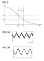
- FIG. 2 is a diagram illustrating an impedance range of an impedance member of the sensor detection controller according to the first embodiment
- FIG. 3A is a diagram illustrating a sinusoidal signal observed when the impedance member is not connected
- FIG. 3B is a diagram illustrating the sinusoidal signal observed when the impedance member is connected
- FIG. 4 is a diagram illustrating characteristics of a radio noise generated from a sensor
- FIG. 5 is a diagram illustrating a sensor detection controller in a fault detection mode according to a modification of the first embodiment
- FIG. 6A is a diagram illustrating a sensor detection controller in a fault detection mode according to a second embodiment of the present invention
- FIG. 6B is a diagram illustrating the sensor detection controller in a normal detection mode according to the second embodiment
- FIG. 7 is a diagram illustrating a sensor detection controller in a fault detection mode according to a modification of the second embodiment
- FIG. 8A is a block diagram illustrating an occupant detection apparatus according to a third embodiment of the present invention
- FIG. 8B is a diagram illustrating a seat equipped with the occupant detection apparatus
- FIG. 9 is a diagram illustrating a sensor detection controller according to a modification of the embodiments.
- connection can mean electrical connection.
- a sensor detection controller 2 according to a first embodiment of the present invention is described below with reference to FIGS. 1A and 1B .
- the sensor detection controller 2 has a fault detection mode and a normal detection mode.
- the sensor detection controller 2 performs a normal detection by using a sensor 1 to detect or measure something.
- the sensor detection controller 2 performs a fault detection to detect a fault, for example, in the sensor 1 itself and in connection between the sensor 1 and the sensor detection controller 2 . That is, in the fault detection mode, it is determined whether the normal detection can be correctly performed.
- the sensor 1 is a capacitive sensor.
- the sensor detection controller 2 includes a signal source 21 , a first switching device 22 , a signal detector 23 , a control circuit 24 , and a resistor R 1 .
- a first end of the signal source 21 is connected to a common potential N, and a second end of the signal source 21 outputs an amplitude signal having a variable amplitude.
- the amplitude signal is a sinusoidal signal.
- the common potential N is a common reference potential of the entire sensor detection controller 2 .
- the common potential N can be a potential of a chassis of a vehicle and can be zero.
- the amplitude and frequency of the sinusoidal signal vary depending on the intended use of the sensor 1 .
- the sinusoidal signal can have a peak-to-peak amplitude of 1.0V relative to a base value of 2.5V and a frequency of from 50 KHz to 90 KHz.
- the sensor 1 has a first electrode plate 11 and a second electrode plate 12 .
- the first electrode plate 11 serves as a detection electrode.
- the second electrode plate 12 is located on a back side of the first electrode plate 11 and serves as a guard electrode with respect to the first electrode plate 11 .
- the first switching device 22 is connected between the signal source 21 and a series circuit of the resistor R 1 and the sensor 1 .
- the first switching device 22 includes a first switch SW 1 and a second switch SW 2 .
- the first switch SW 1 and the second switch SW 2 are independently controller by the control circuit 24 to switch a signal path through which the sinusoidal signal (i.e., current I 1 ) is applied to the sensor 1 .
- the first switch SW 1 and the second switch SW 2 are contact switches.
- the first switch SW 1 and the second switch SW 2 can be relays (e.g., electromagnetic relays, semiconductor relays), transistors (e.g., bipolar transistors, field-effect transistors), photocouplers, or the like.
- the second switch SW 2 is switched to a terminal b.
- the terminal b is connected to the common potential N.
- the second switch SW 2 is switched to a terminal a.
- the second switch SW 2 is switched between the terminal a and the terminal b in accordance with a switch signal from the control circuit 24 .
- the first switch SW 1 is used to select one sensor 1 targeted for the fault detection and the normal detection from multiple sensors 1 .
- the signal detector 23 detects a change in voltage or current of the sinusoidal signal, when the sinusoidal signal is applied. For example, the signal detector 23 detects a change in voltage or current between a base terminal of the first switch SW 1 and the terminal a of the second switch SW 2 .
- the second electrode plate 12 is connected to the common potential N, and the sinusoidal signal is applied by the signal source 21 to the first electrode plate 11 so that the current I 1 can flow between the first electrode plate 11 and the second electrode plate 12 .
- the signal detector 23 calculates an impedance value of the sensor 1 based on the current or voltage and determines based on the impedance value whether a fault occurs.
- the sinusoidal signal is applied by the signal source 21 to both the first electrode plate 11 and the second electrode plate 12 so that the second electrode plate 12 can serve as a guard electrode with respect to the first electrode plate 11 .
- the sinusoidal signal is applied by the signal source 21 to both the first electrode plate 11 and the second electrode plate 12 so that the second electrode plate 12 can serve as a guard electrode with respect to the first electrode plate 11 .
- an object located on a front side of the first electrode plate 11 can be a target for detection.
- a capacitor Ch impedance Zh
- impedance values of the sensor 1 and the human body can be calculated based on the current and voltage detected when the sinusoidal signal is applied.
- the control circuit 24 controls the overall sensor detection controller 2 , in particular, the first switching device 22 and the signal detector 23 .
- the signal detector 23 and the control circuit 24 can be implemented as software or hardware.
- the signal detector 23 and the control circuit 24 can be software controlled by using a CPU or a microcomputer.
- the signal detector 23 and the control circuit 24 can be hardware controlled by using an IC (e.g., LSI, gate array) or a circuit device such as a transistor.
- the resistor R 1 corresponding to an impedance member Z 1 is connected between the first switching device 22 and the sensor 1 . That is, the resistor R 1 is connected to the signal path through which the sinusoidal signal is applied to the sensor 1 .
- An impedance (i.e., resistance) value Z of the resistor R 1 is determined as follows.
- the phasors of the voltage value V, the current value I, the impedance value Z, and the impedance value Z mg are given as follows:
- V . V m ⁇ e - j ⁇ ( ⁇ ⁇ ⁇ t - ⁇ )
- I . I m ⁇ e - j ⁇ ( ⁇ ⁇ ⁇ t - ⁇ - ⁇ )
- Z . Z Re + j ⁇ ⁇ Z Im
- Z . mg Z mg ⁇ ⁇ Re + j ⁇ ⁇ Z mg ⁇ ⁇ Im
- t is a time
- ⁇ is an angular velocity
- ⁇ is a phase
- ⁇ is a phase difference between voltage and current
- V m is a maximum amplitude of voltage
- I m is a maximum amplitude of current
- Z mgRe is an real part of Z mg
- Z mgIm is an imaginary part of Z mg .
- the impedance value Z mg of the sensor 1 is an impedance value between the first electrode plate 11 and the second electrode plate 12 .
- the impedance value Z mg of the sensor 1 is discussed in detail below.
- the capacitance part When the capacitance part is dominant, the real part can be negligible (i.e., Z mgRe ⁇ 0). Therefore, the impedance value Z mg can be approximated to the imaginary part Z mgIm .
- the impedance value Z mg is much smaller than the impedance value Z of the resistor R 1 (i.e.,
- the phase difference between the voltage and current becomes almost zero. Therefore, the impedance value Z of the resistor R 1 can be given as follows:
- ⁇ Z ⁇ ⁇ ( ⁇ Z a ⁇ , ⁇ Z b ⁇ ) V m 2 I m 2 + Z mg ⁇ ⁇ Im 2 ( 3 )
- a maximum current value to which the signal source 21 can supply the sinusoidal signal without distortion in the fault detection mode is I lim . Further, it is assumed that a minimum current value necessary for both the fault detection and normal detection is I low . In this case, when the impedance value Z of the resistor R 1 is set to an impedance value Za in a range satisfying the following inequality (4), a radio noise can be reduced without affecting a detection performance:
- the inequality (4) is derived by substituting I lim and I low into I m of the equation (3).
- can be represented by a graph shown in FIG. 2 .
- the longitudinal axis represents the current
- the horizontal axis represents the resistance.
- FIG. 3A shows the sinusoidal signal observed when the resistor R 1 shown in FIGS. 1A and 1B is not connected.
- FIG. 3B shows the sinusoidal signal observed when the resistor R 1 shown in FIGS. 1A and 1B is connected.
- distortion in the sinusoidal signal is less when the resistor R 1 is connected than when the resistor R 1 is not connected.
- the longitudinal axis represents a noise peak
- the horizontal axis represents a frequency.
- the radio noise characteristics were measured while changing the impedance value of the resistor R 1 to 0 ⁇ (i.e., no R 1 ), 500 ⁇ , 750 ⁇ , and 3.0 k ⁇ .
- the sinusoidal signal has a fundamental frequency f of 100 kHz.
- 2 f , 3 f , . . . , and 9 f represents a second-order harmonic, a third-order harmonic, . . . , and a ninth-order harmonic, respectively.
- FIG. 4 shows that the radio noise is less when the resistor R 1 having the impedance value of 500 ⁇ is connected than when no resistor R 1 is connected. Further, FIG. 4 shows that the radio noise is less when the resistor R 1 having the impedance value of 750 ⁇ or 3.0 k ⁇ is connected than when the resistor R 1 having the impedance value of 500 ⁇ is connected.
- the resistor R 1 is connected between the first switch SW 1 and the first electrode plate 11 .
- the resistor R 1 can be connected to any position in the signal path through which the current I 1 flows.
- the resistor R 1 can be connected between the terminal c of the second switch SW 2 and the second electrode plate 12 .
- the resistor R 1 can include a first resistor R 11 connected between the first switch SW 1 and the first electrode plate 11 and a second resistor R 12 connected between the terminal c of the second switch SW 2 and the second electrode plate 12 .
- FIG. 5 corresponding to FIG. 1A
- ) of the resistor R 1 is set equal to the resistance values (i.e., impedance values
- the sensor detection controller 2 includes the signal source 21 for applying the sinusoidal signal (i.e., amplitude signal) to the sensor 1 , the first switching device 22 for switching the signal path, through which the sinusoidal signal is applied, between the fault detection mode and the normal detection mode, the signal detector 23 for detecting the change in voltage or current on the sinusoidal signal when the sinusoidal signal is applied, the control circuit 24 for controlling the first switching device 22 and the signal detector 23 , and the impedance member Z 1 (i.e., resistor R 1 ) connected to the signal path.
- the signal source 21 for applying the sinusoidal signal (i.e., amplitude signal) to the sensor 1
- the first switching device 22 for switching the signal path, through which the sinusoidal signal is applied, between the fault detection mode and the normal detection mode
- the signal detector 23 for detecting the change in voltage or current on the sinusoidal signal when the sinusoidal signal is applied
- the control circuit 24 for controlling the first switching device 22 and the signal detector 23
- the impedance member Z 1 i.e., resist
- the impedance value Z of the impedance member Z 1 (i.e., resistance value of the resistor R 1 ) is set so that the current value I of the current I 1 on the signal path is equal to or less than the maximum current value I lim to which the signal source 21 is capable of applying the sinusoidal signal without distortion and equal to or greater than the minimum current value I low necessary for both the fault detection and the normal detection.
- the radio noise can be reduced in the fault detection mode.
- the current value I of the current I 1 flowing through the signal path is greater or equal to the minimum current value I low , the detection can be surely performed by using the sensor 1 .
- the impedance value Z of the impedance member Z 1 is set to the impedance value Za satisfying the inequality (4).
- the current value I of the current I 1 flowing through the signal path in the fault detection mode is less or equal to the maximum current value I lim so that the fault detection can be performed while reducing the radio noise
- the current value I of the current I 1 flowing through the signal path in the normal detection mode is greater or equal to the minimum current value I low so that the normal detection can be surely performed by using the sensor 1 .
- the impedance member Z 1 is provided by al least one resistor. Specifically, in FIGS. 1A and 1 B, the impedance member Z 1 is provided by one resistor R 1 , and in FIG. 5 , the impedance member Z 1 is provided by two resistors R 11 , R 12 . In such an approach, the impedance member Z 1 can be easily provided at low cost. Accordingly, the sensor detection controller 2 can be easily manufactured at low cost.
- the impedance member Z 1 can be provided by three or more resistors in the same manner to obtain the same advantage.
- the senor 1 is a capacitive sensor having a predetermined capacitance and including at least two electrodes.
- the sensor 1 performs a detection based on a change in the capacitance. Even if the impedance value (
- FIG. 6A is a diagram illustrating the sensor detection controller 2 in the fault detection mode
- FIG. 6B is a diagram illustrating the sensor detection controller 2 in the normal detection mode.
- the sensor detection controller 2 includes a second switching device 25 .
- the second switching device 25 is configured in almost the same manner as the second switch SW 2 of the first switching device 22 and connected between the second switch SW 2 and the second electrode plate 12 . Specifically, a terminal c of the second switching device 25 is connected to the terminal c of the second switch SW 2 , a terminal a of the second switching device 25 is connected through a short circuit Sc to the second electrode plate 12 , and a terminal b of the second electrode plate 12 is connected to a first end of a resistor R 2 . A second end of the resistor R 2 is connected to the second electrode plate 12 .
- a voltage V 2 is applied by the signal source 21 to the sensor 1 .
- the voltage V 2 can be equal to or different from the voltage V 1 of the first embodiment.
- the second switch SW 2 is switched to the terminal b connected to the common potential N, and the second switching device 25 is switched to the terminal b connected to the resistor R 2 .
- the second switch SW 2 is switched to the terminal a, and the second switching device 25 is switched to the terminal a that is connected to the short circuit Sc.
- Each of the second switch SW 2 and the second switching device 25 is switched between the terminal a and the terminal b in accordance to the switch signal from the control circuit 24 .
- the resistor R 2 corresponds to an impedance member Z 2 .
- An impedance (i.e., resistance) value Z of the resistor R 2 is set to an impedance value Zb satisfy the following inequality (6):
- I lim represents the maximum current value to which the signal source 21 can supply the sinusoidal signal without distortion in the fault detection mode
- I fail represents a minimum current value necessary for the fault detection.
- the minimum current value I fail is equal to or less than the minimum current value I low necessary for both the fault detection and the normal detection.
- the resistor R 2 and the short circuit Sc are selectively connected between the second switch SW 2 and the second electrode plate 12 .
- the resistor R 2 and the short circuit Sc can be selectively connected to any position in the signal path through which the current I 2 flows.
- the second switching device 25 , the short circuit Sc, and the resistor R 2 can be connected between the first switch SW 1 and the first electrode plate 11 .
- the resistor R 2 can be connected between the terminal b of the second switch SW 2 and the common potential N. In such an approach, the second switching device 25 and the short circuit Sc can be removed so that the manufacturing cost of the sensor detection controller 2 can be reduced.
- the impedance member Z 2 can be provided by multiple resistors.
- the sensor detection controller 2 includes the signal source 21 for applying the sinusoidal signal (i.e., amplitude signal) to the sensor 1 , the first switching device 22 for switching the signal path, through which the sinusoidal signal is applied, between the fault detection mode and the normal detection mode, the signal detector 23 for detecting the change in voltage or current of the sinusoidal signal when the sinusoidal signal is applied, the control circuit 24 for controlling the first switching device 22 and the signal detector 23 , the impedance member Z 2 (i.e., resistor R 2 ) connected to the signal path through which the sinusoidal signal is applied, the short circuit Sc for short-circuiting the impedance member Z 2 , and the second switching device 25 for switching the signal path to the impedance member Z 2 side or the short circuit Sc side.
- the signal source 21 for applying the sinusoidal signal (i.e., amplitude signal) to the sensor 1
- the first switching device 22 for switching the signal path, through which the sinusoidal signal is applied, between the fault detection mode and the normal detection mode
- the signal detector 23 for
- the second switching device 25 selectively activates and deactivates the short circuit Sc.
- the second switching device 25 selectively connects or disconnects the impedance member Z 2 to or from the signal path.
- the impedance value Z of the impedance member Z 2 i.e., resistance value of the resistor R 2
- the impedance value Z of the impedance member Z 2 is set so that the current value I of the current I 2 on the signal path is equal to or less than the maximum current value I lim to which the signal source 21 is capable of applying the sinusoidal signal without distortion and equal to or greater than the minimum current value I fail necessary for the fault detection. That is, the current value I of the current I 2 on the signal path can be less than the minimum current value I low necessary for both the fault detection and the normal detection.
- the fault detection can be performed while reducing the radio noise. Further, since the current value I of the current I 2 flowing through the signal path in the fault detection mode is greater or equal to the minimum current value I fail , the fault detection can be surely performed. In the normal detection mode, the resistor R 2 is disconnected from the signal path and thus does not affect a detection performance. Therefore, the normal detection can be surely performed by using the sensor 1 .
- the impedance value Z of the impedance member Z 2 (i.e., resistance value of the resistor R 2 ) is set to the impedance value Zb satisfying the inequality (6).
- the current value I of the current I 2 flowing through the signal path in the fault detection mode is less or equal to the maximum current value I lim so that the fault detection can be performed while reducing the radio noise, and the current value I of the current I 2 flowing through the signal path in the fault detection mode is greater or equal to the minimum current value I fail so that the fault detection can be surely performed.
- the resistor R 2 since the resistor R 2 is disconnected from the signal path and does not affect a detection performance, the normal detection can be surely performed by using the sensor 1 .
- FIG. 8A is a block diagram of the occupant detection apparatus 3 .
- FIG. 8B is a diagram illustrating a side view of a vehicle seat 4 equipped with the occupant detection apparatus 3 .
- the occupant detection apparatus 3 includes the sensor detection controller 2 of the first embodiment or the second embodiment.
- the occupant detection apparatus 3 includes a connector 31 , a wiring member 32 , and a capacitive sensor 33 in addition to the sensor detection controller 2 .
- the capacitive sensor 33 corresponds to the sensor 1 of the first embodiment or the second embodiment.
- the number of each component of the occupant detection apparatus 3 can vary depending on a shape of the vehicle seat 4 , a position on the vehicle seat 4 at which detection is to be performed, and/or the like.
- the sensor detection controller 2 can be incorporated in an electronic control unit (or another control unit) or can be provided separately from such an electronic control unit.
- the occupant detection apparatus 3 except the sensor detection controller 2 is installed in the vehicle seat 4 .
- the vehicle seat 4 includes a first cushion pad 41 , a second cushion pad 43 , and a seat frame 44 .
- the first cushion pad 41 is used as a seat base mainly for holding the hip and the thighs of an occupant of the vehicle.
- a front surface of the first cushion pad 41 is covered with a cover 42 .
- the capacitive sensor 33 and the wiring member 32 are placed between the first cushion pad 41 and the cover 42 .
- the capacitive sensor 33 is placed in such a manner that the first electrode plate 11 is located on the front surface side (top side of FIG.
- the wiring member 32 extends from the front surface to the back surface of the first cushion pad 41 through a through hole 41 a of the first cushion pad 41 and is connected to the connector 31 that is located on the back surface of the first cushion pad 41 .
- the second cushion pad 43 is used as a seat back mainly for holding the back of the occupant. Like the first cushion pad 41 , the second cushion pad 43 can be covered with a cover.
- the seat flame 44 is located on a bottom portion of the vehicle seat 4 and separated from the capacitive sensor 33 .
- the seat flame 44 is connected to the common potential N (i.e., ground G) through a vehicle chassis 5 .
- N i.e., ground G
- the capacitor Ch i.e., impedance Zh
- the sensor detection controller 2 detects a change in capacitance of the capacitive sensor 33 , and it is determined based on the change in the capacitance whether the occupant is seated on the vehicle seat 4 .
- the occupant detection apparatus 3 includes one capacitive sensor 33 .
- the occupant detection apparatus 3 can include two or more capacitive sensors 33 .
- the occupant detection apparatus 3 includes the sensor detection controller 2 and at least one capacitive sensor 33 .
- the capacitive sensor 33 is mounted on the front surface side of the vehicle seat 4 . so that the capacitance of the capacitive sensor 33 can change according to whether the occupant is seated on the vehicle seat 4 . Since the occupant detection apparatus 3 includes the sensor detection controller 2 , the fault in the capacitive sensor 33 can be easily detected. Thus, the occupant detection apparatus 3 can surely determine whether the occupant is seated on the vehicle seat 4 .
- the sensor detection controller 2 is configured to perform the fault detection and the normal detection of one sensor 1 .
- the sensor detection controller 2 can be configured to perform the fault detection and the normal detection of two or more sensors 1 .
- the sensor detection controller 2 can be configured to perform the fault detection and the normal detection of two sensors 1 A and 1 B.
- the sensor detection controller 2 shown in FIG. 9 differs from the sensor detection controller 2 shown in FIGS. 1A and 1B in the following three ways.
- the first switching device 22 further includes a third switch SW 3 and a fourth switch SW 4 .
- the sensor detection controller 2 is configured to perform the fault detection and the normal detection of two sensors 1 A and 1 B.
- the resistor R 1 i.e., the impedance member Z 1
- the resistor R 1 is connected between the first switching device 22 and each of the sensors 1 A and 1 B.
- the sensor detection controller 2 shown in FIG. 9 selects the sensor 1 A or the sensor 1 B by using the first switch SW 1 or the third switch SW 3 , respectively.
- the sensor detection controller 2 performs the fault detection and the normal detection of the selected sensor.
- the first switch SW 1 is OFF, and the third switch SW 3 is ON to select the sensor 1 B.
- the sinusoidal signal is applied to the sensor 1 B through a signal path indicated by a broken line in FIG. 9 . Since the resistor R 1 (i.e., resistor Z 1 ) is connected to the signal path, the same advantages as the first and second embodiments can be obtained.
- the sensor detection controller 2 performs the fault detection and the normal detection of two sensors.
- the sensor detection controller 2 can perform the fault detection and the normal detection of three or more sensors.
- the sensor 1 is a capacitive sensor.
- the sensor 1 can be a sensor other than a capacitive sensor, as long as the sensor 1 performs a detection operation by using electromagnetic waves or sound waves.
- the sensor 1 can be a radio frequency sensor (e.g., radar) for radiating radio waves from a radio wave oscillator, a laser sensor for radiating laser (i.e., electromagnetic waves) form a laser oscillator, an infrared sensor for radiating infrared rays (i.e., electromagnetic waves) from a radiator, and a sound wave sensor (e.g., sonar) for radiating sound waves including ultrasound waves from a sound source.
- a radio frequency sensor e.g., radar
- laser sensor for radiating laser (i.e., electromagnetic waves) form a laser oscillator
- an infrared sensor for radiating infrared rays (i.e., electromagnetic waves) from a radiator
- a sound wave sensor e.g., sonar
- radio noise i.e., harmonics
- the radio noise can be reduced by connecting the impedance to the sensor. Further, since the minimum current value necessary for detection is ensured, the detection can be surely performed by using the sensor.
- the amplitude signal is a sinusoidal signal.
- the amplitude signal can be a signal other than a sinusoidal signal.
- the amplitude signal can be a pulse signal, a triangle wave signal, a sawtooth wave signal, or the like. Even when such an amplitude signal is applied to perform detection, the detection can be surely performed by using the sensor 1 .
- the impedance member Z 1 , Z 2 are provided by the resistors R 1 , R 2 , R 11 , and R 12 .
- the impedance can be provided by a capacitor or a coil instead of or in addition to a resistor.
- the impedance can be provided by a combination of a resistor, a capacitor, and a coil that are connected in series or in parallel to form a circuit such as a RLC circuit or a LC circuit. In such a case, the total impedance of the circuit is set to satisfy the inequality (4) or (6). In such an approach, even when the impedance is provided by various types of passive elements, the radio noise can be reduced, and the detection can be surely performed by using the sensor 1 .
Landscapes
- Engineering & Computer Science (AREA)
- Aviation & Aerospace Engineering (AREA)
- Transportation (AREA)
- Mechanical Engineering (AREA)
- Computer Networks & Wireless Communication (AREA)
- Geophysics And Detection Of Objects (AREA)
- Seats For Vehicles (AREA)
Abstract
Description
Claims (11)
Applications Claiming Priority (2)
| Application Number | Priority Date | Filing Date | Title |
|---|---|---|---|
| JP2010-203378 | 2010-09-10 | ||
| JP2010203378A JP5124627B2 (en) | 2010-09-10 | 2010-09-10 | Sensor detection controller and occupant detection device |
Publications (2)
| Publication Number | Publication Date |
|---|---|
| US20120065845A1 US20120065845A1 (en) | 2012-03-15 |
| US8335617B2 true US8335617B2 (en) | 2012-12-18 |
Family
ID=45807506
Family Applications (1)
| Application Number | Title | Priority Date | Filing Date |
|---|---|---|---|
| US13/199,752 Expired - Fee Related US8335617B2 (en) | 2010-09-10 | 2011-09-08 | Sensor detection controller and occupant detection apparatus having the same |
Country Status (2)
| Country | Link |
|---|---|
| US (1) | US8335617B2 (en) |
| JP (1) | JP5124627B2 (en) |
Cited By (3)
| Publication number | Priority date | Publication date | Assignee | Title |
|---|---|---|---|---|
| US20140043047A1 (en) * | 2012-08-10 | 2014-02-13 | Delphi Technologies, Inc. | Occupant detection system and method |
| US9266454B2 (en) | 2013-05-15 | 2016-02-23 | Gentherm Canada Ltd | Conductive heater having sensing capabilities |
| US9701232B2 (en) | 2013-10-11 | 2017-07-11 | Gentherm Gmbh | Occupancy sensing with heating devices |
Families Citing this family (7)
| Publication number | Priority date | Publication date | Assignee | Title |
|---|---|---|---|---|
| US9252682B2 (en) * | 2011-06-28 | 2016-02-02 | Kyocera Corporation | Grid-connected inverter apparatus and control method therefor |
| US9126502B2 (en) * | 2012-08-14 | 2015-09-08 | Delphi Technologies, Inc. | Dual electrode occupant detection system and method |
| JP5941822B2 (en) * | 2012-10-26 | 2016-06-29 | 株式会社日本自動車部品総合研究所 | Capacitive occupant detection device |
| KR101619599B1 (en) * | 2014-08-08 | 2016-05-10 | 현대자동차주식회사 | Vehicle Collision Avoidance Method and Apparatus of Low Power Consumption Based on Fused Radar Sensors |
| CN104898009B (en) * | 2015-03-17 | 2024-02-13 | 杭州鸿雁电器有限公司 | Detection equipment and detection method for online sensing equipment |
| KR101915082B1 (en) * | 2015-11-06 | 2018-11-05 | 타이코에이엠피 주식회사 | Mat system detecting breakdown of mat sensing embarkation of user |
| KR102423301B1 (en) * | 2017-12-11 | 2022-07-19 | 주식회사 엘지에너지솔루션 | Apparatus and method for preventing short |
Citations (7)
| Publication number | Priority date | Publication date | Assignee | Title |
|---|---|---|---|---|
| US5386695A (en) * | 1993-01-21 | 1995-02-07 | Honda Giken Kogyo Kabushiki Kaisha | Air-fuel ratio control system for internal combustion engines, having catalytic converter deterioration-detecting function |
| US5676119A (en) * | 1995-09-25 | 1997-10-14 | Honda Giken Kogyo Kabushiki Kaisha | Air-fuel ratio control system for internal combustion engines |
| US5743085A (en) * | 1993-04-09 | 1998-04-28 | Hitachi, Ltd. | Diagnostic equipment for an exhaust gas cleaning apparatus |
| US6047634A (en) * | 1996-09-03 | 2000-04-11 | The Nippon Signal Co., Ltd. | Fail-safe automatic sliding operation control apparatus for press |
| US7102527B2 (en) * | 2001-03-02 | 2006-09-05 | Elesys North America Inc. | Multiple sensor vehicle occupant detection for air bag deployment control |
| US7164117B2 (en) * | 1992-05-05 | 2007-01-16 | Automotive Technologies International, Inc. | Vehicular restraint system control system and method using multiple optical imagers |
| US20080100425A1 (en) | 2006-10-31 | 2008-05-01 | Denso Corporation | Capacitance type seat occupant sensor system |
Family Cites Families (3)
| Publication number | Priority date | Publication date | Assignee | Title |
|---|---|---|---|---|
| JPH04237160A (en) * | 1991-01-22 | 1992-08-25 | Nec Corp | Bipolar cmos composite type semiconductor device |
| JP4300478B2 (en) * | 2004-03-25 | 2009-07-22 | 株式会社デンソー | Seating sensor |
| JP4324877B2 (en) * | 2005-03-07 | 2009-09-02 | 株式会社デンソー | Capacitive occupant detection sensor |
-
2010
- 2010-09-10 JP JP2010203378A patent/JP5124627B2/en not_active Expired - Fee Related
-
2011
- 2011-09-08 US US13/199,752 patent/US8335617B2/en not_active Expired - Fee Related
Patent Citations (10)
| Publication number | Priority date | Publication date | Assignee | Title |
|---|---|---|---|---|
| US7164117B2 (en) * | 1992-05-05 | 2007-01-16 | Automotive Technologies International, Inc. | Vehicular restraint system control system and method using multiple optical imagers |
| US5386695A (en) * | 1993-01-21 | 1995-02-07 | Honda Giken Kogyo Kabushiki Kaisha | Air-fuel ratio control system for internal combustion engines, having catalytic converter deterioration-detecting function |
| US5743085A (en) * | 1993-04-09 | 1998-04-28 | Hitachi, Ltd. | Diagnostic equipment for an exhaust gas cleaning apparatus |
| US5921078A (en) * | 1993-04-09 | 1999-07-13 | Hitachi, Ltd. | Diagnostic equipment for an exhaust gas cleaning apparatus |
| US6089016A (en) * | 1993-04-09 | 2000-07-18 | Hitachi, Ltd. | Diagnostic equipment for an exhaust gas cleaning apparatus |
| US5676119A (en) * | 1995-09-25 | 1997-10-14 | Honda Giken Kogyo Kabushiki Kaisha | Air-fuel ratio control system for internal combustion engines |
| US6047634A (en) * | 1996-09-03 | 2000-04-11 | The Nippon Signal Co., Ltd. | Fail-safe automatic sliding operation control apparatus for press |
| US7102527B2 (en) * | 2001-03-02 | 2006-09-05 | Elesys North America Inc. | Multiple sensor vehicle occupant detection for air bag deployment control |
| US20080100425A1 (en) | 2006-10-31 | 2008-05-01 | Denso Corporation | Capacitance type seat occupant sensor system |
| JP2008111809A (en) | 2006-10-31 | 2008-05-15 | Denso Corp | Capacitive occupant detection sensor |
Cited By (6)
| Publication number | Priority date | Publication date | Assignee | Title |
|---|---|---|---|---|
| US20140043047A1 (en) * | 2012-08-10 | 2014-02-13 | Delphi Technologies, Inc. | Occupant detection system and method |
| US9061603B2 (en) * | 2012-08-10 | 2015-06-23 | Delphi Technologies, Inc. | Occupant detection system and method |
| US9266454B2 (en) | 2013-05-15 | 2016-02-23 | Gentherm Canada Ltd | Conductive heater having sensing capabilities |
| US10075999B2 (en) | 2013-05-15 | 2018-09-11 | Gentherm Gmbh | Conductive heater having sensing capabilities |
| US9701232B2 (en) | 2013-10-11 | 2017-07-11 | Gentherm Gmbh | Occupancy sensing with heating devices |
| US10076982B2 (en) | 2013-10-11 | 2018-09-18 | Gentherm Gmbh | Occupancy sensing with heating devices |
Also Published As
| Publication number | Publication date |
|---|---|
| JP5124627B2 (en) | 2013-01-23 |
| US20120065845A1 (en) | 2012-03-15 |
| JP2012058145A (en) | 2012-03-22 |
Similar Documents
| Publication | Publication Date | Title |
|---|---|---|
| US8335617B2 (en) | Sensor detection controller and occupant detection apparatus having the same | |
| US7701338B2 (en) | Occupant detection system and method of determining occupant | |
| US6445294B1 (en) | Proximity sensor | |
| US7626396B2 (en) | Systems and methods for electrical leakage detection and compensation | |
| US9731627B2 (en) | Capacitive sensor | |
| EP1427612B1 (en) | Conductive e-field occupant sensing | |
| US20130334844A1 (en) | Capacitive occupant detection system | |
| US12221015B2 (en) | Sensor arrangement for capacitive position detection of an object | |
| CN117223221B (en) | Low cost, protected capacitive sensing circuit for loading mode operation of a capacitive sensor employing a heater element | |
| US20110285408A1 (en) | Occupant detection apparatus | |
| JP2020505610A (en) | Robust, low-cost capacitive measurement system | |
| US20230089289A1 (en) | Electric circuit structure for an alternating heating and capacitive measuring mode, and associated method | |
| RU2477837C2 (en) | Object detection device for mechanical transport vehicle | |
| CN102246417B (en) | Sensor device for detecting an object in a detection area | |
| US12384441B2 (en) | Electric circuit structure for an alternating heating and capacitive measuring mode with function test, and associated method | |
| US10128698B2 (en) | Device and method for detecting an object within a wireless charging region | |
| JP4324877B2 (en) | Capacitive occupant detection sensor | |
| JP6599758B2 (en) | Buckle and in-vehicle system | |
| US8487632B2 (en) | Electrostatic sensor and occupant detecting device having the same | |
| JP2009053074A (en) | Electric field detection device | |
| JP5561513B2 (en) | Capacitance sensor and vehicle proximity sensor using the same | |
| US8937478B2 (en) | Electrostatic occupant detection system | |
| LU101816B1 (en) | Sensor Arrangement for Capacitive Position Detection of an Object | |
| US11821762B2 (en) | System for capacitive object detection | |
| WO2025243647A1 (en) | Sensor device |
Legal Events
| Date | Code | Title | Description |
|---|---|---|---|
| AS | Assignment |
Owner name: NIPPON SOKEN, INC., JAPAN Free format text: ASSIGNMENT OF ASSIGNORS INTEREST;ASSIGNORS:SATAKE, MASAYOSHI;MAEDA, NOBORU;MORI, HIROYUKI;AND OTHERS;SIGNING DATES FROM 20110831 TO 20110904;REEL/FRAME:027053/0293 Owner name: DENSO CORPORATION, JAPAN Free format text: ASSIGNMENT OF ASSIGNORS INTEREST;ASSIGNORS:SATAKE, MASAYOSHI;MAEDA, NOBORU;MORI, HIROYUKI;AND OTHERS;SIGNING DATES FROM 20110831 TO 20110904;REEL/FRAME:027053/0293 |
|
| ZAAA | Notice of allowance and fees due |
Free format text: ORIGINAL CODE: NOA |
|
| ZAAB | Notice of allowance mailed |
Free format text: ORIGINAL CODE: MN/=. |
|
| STCF | Information on status: patent grant |
Free format text: PATENTED CASE |
|
| FEPP | Fee payment procedure |
Free format text: PAYOR NUMBER ASSIGNED (ORIGINAL EVENT CODE: ASPN); ENTITY STATUS OF PATENT OWNER: LARGE ENTITY |
|
| FPAY | Fee payment |
Year of fee payment: 4 |
|
| MAFP | Maintenance fee payment |
Free format text: PAYMENT OF MAINTENANCE FEE, 8TH YEAR, LARGE ENTITY (ORIGINAL EVENT CODE: M1552); ENTITY STATUS OF PATENT OWNER: LARGE ENTITY Year of fee payment: 8 |
|
| FEPP | Fee payment procedure |
Free format text: MAINTENANCE FEE REMINDER MAILED (ORIGINAL EVENT CODE: REM.); ENTITY STATUS OF PATENT OWNER: LARGE ENTITY |
|
| LAPS | Lapse for failure to pay maintenance fees |
Free format text: PATENT EXPIRED FOR FAILURE TO PAY MAINTENANCE FEES (ORIGINAL EVENT CODE: EXP.); ENTITY STATUS OF PATENT OWNER: LARGE ENTITY |
|
| STCH | Information on status: patent discontinuation |
Free format text: PATENT EXPIRED DUE TO NONPAYMENT OF MAINTENANCE FEES UNDER 37 CFR 1.362 |
|
| FP | Lapsed due to failure to pay maintenance fee |
Effective date: 20241218 |