US8327896B2 - Split rear wheel assembly for a motorcycle - Google Patents
Split rear wheel assembly for a motorcycle Download PDFInfo
- Publication number
- US8327896B2 US8327896B2 US12/272,039 US27203908A US8327896B2 US 8327896 B2 US8327896 B2 US 8327896B2 US 27203908 A US27203908 A US 27203908A US 8327896 B2 US8327896 B2 US 8327896B2
- Authority
- US
- United States
- Prior art keywords
- tire
- motorcycle
- sidewall
- bead
- axle
- Prior art date
- Legal status (The legal status is an assumption and is not a legal conclusion. Google has not performed a legal analysis and makes no representation as to the accuracy of the status listed.)
- Expired - Fee Related, expires
Links
Images



Classifications
-
- B—PERFORMING OPERATIONS; TRANSPORTING
- B60—VEHICLES IN GENERAL
- B60B—VEHICLE WHEELS; CASTORS; AXLES FOR WHEELS OR CASTORS; INCREASING WHEEL ADHESION
- B60B11/00—Units comprising multiple wheels arranged side by side; Wheels having more than one rim or capable of carrying more than one tyre
- B60B11/04—Wheels with a rim capable of carrying more than one tyre
-
- B—PERFORMING OPERATIONS; TRANSPORTING
- B60—VEHICLES IN GENERAL
- B60C—VEHICLE TYRES; TYRE INFLATION; TYRE CHANGING; CONNECTING VALVES TO INFLATABLE ELASTIC BODIES IN GENERAL; DEVICES OR ARRANGEMENTS RELATED TO TYRES
- B60C19/00—Tyre parts or constructions not otherwise provided for
- B60C19/001—Tyres requiring an asymmetric or a special mounting
-
- B—PERFORMING OPERATIONS; TRANSPORTING
- B60—VEHICLES IN GENERAL
- B60C—VEHICLE TYRES; TYRE INFLATION; TYRE CHANGING; CONNECTING VALVES TO INFLATABLE ELASTIC BODIES IN GENERAL; DEVICES OR ARRANGEMENTS RELATED TO TYRES
- B60C3/00—Tyres characterised by the transverse section
- B60C3/06—Tyres characterised by the transverse section asymmetric
-
- B—PERFORMING OPERATIONS; TRANSPORTING
- B60—VEHICLES IN GENERAL
- B60C—VEHICLE TYRES; TYRE INFLATION; TYRE CHANGING; CONNECTING VALVES TO INFLATABLE ELASTIC BODIES IN GENERAL; DEVICES OR ARRANGEMENTS RELATED TO TYRES
- B60C2200/00—Tyres specially adapted for particular applications
- B60C2200/10—Tyres specially adapted for particular applications for motorcycles, scooters or the like
-
- Y—GENERAL TAGGING OF NEW TECHNOLOGICAL DEVELOPMENTS; GENERAL TAGGING OF CROSS-SECTIONAL TECHNOLOGIES SPANNING OVER SEVERAL SECTIONS OF THE IPC; TECHNICAL SUBJECTS COVERED BY FORMER USPC CROSS-REFERENCE ART COLLECTIONS [XRACs] AND DIGESTS
- Y10—TECHNICAL SUBJECTS COVERED BY FORMER USPC
- Y10T—TECHNICAL SUBJECTS COVERED BY FORMER US CLASSIFICATION
- Y10T152/00—Resilient tires and wheels
- Y10T152/10—Tires, resilient
- Y10T152/10495—Pneumatic tire or inner tube
Definitions
- This invention is in the field of rear wheels for a motorcycle and more particularly a split rear tire for a motorcycle.
- kits for motorcycles that allow rear tires up to 8′′ or more in width to be added to a motorcycle.
- these kits include a rear frame for the rear wheel that replaces the stock rear frame on the motorcycle.
- the belt running from the transmission to the sprocket on the rear wheel is usually moved further out to the side of the motorcycle in order to clear the new wider rear wheel.
- moving the belt out further to the side of the motorcycle has disadvantages.
- moving the belt further out from the transmission makes it stick out that much further from the side of the motorcycle and creates a greater risk of something getting hit or caught by the belt (such as the ankle or leg of a rider). This is even more dangerous when you consider that while the motorcycle is in motion this belt is often moving quite fast.
- the further the belt is moved out from the side of the motorcycle the more offset the power being transferred to the rear wheel of the motorcycle which can cause a number of complications.
- the width of rear wheel that can be used is also limited by the amount this belt can be moved out to the side of the motorcycle so that it clears the new wider rear wheel of the motorcycle.
- the present invention provides an inflatable tire comprising a first bead and a second bead adapted to be mounted on a rim.
- a first sidewall extends upward from the first bead to a first edge of a substantially horizontal tread face located substantially directly above the first bead.
- a second sidewall extends upward from the second bead and then curves toward a second edge of the tread face such that a curved tire surface is provided between the second bead and the second edge of the tread face.
- the tread face has a width that is less than half of a distance between the first and second beads.
- the present invention provides a rear wheel apparatus for a motorcycle.
- the apparatus comprises a right wheel mounted on an axle, the right wheel comprising a right tire mounted on a right rim and with a left sidewall extending upward from a left bead to a left edge of a substantially horizontal tread face located substantially directly above the left bead, and a right sidewall extending upward from a right bead and then curving toward a right edge of the tread face such that a curved tire surface is provided between the right bead and the right edge of the tread face, wherein the tread face has a width that is less than half of a distance between the right and left beads; a left wheel mounted on the axle, the left wheel comprising a left tire mounted on a left rim and with a right sidewall extending upward from a right bead to a right edge of a substantially horizontal tread face located substantially directly above the right bead, and a left sidewall extending upward from the left bead and then curving toward a left edge of the
- the right and left wheels are mounted on the axle such that a gap is defined between the right and left wheels, and a drive extends through the gap to the axle to rotate the right and left wheels and drive the motorcycle.
- the right and left tires are configured such that when the motorcycle is oriented in a substantially vertical position, tread faces of the right and left wheels are on a ground surface, and such that when the motorcycle is in a leaning position, one of the right and left wheels is above the ground surface, and the motorcycle is supported on the curved tire surface of the other of the right and left tires.
- the power transmission from the engine in the motorcycle can be oriented along a centerline of the motorcycle and the rear wheel instead of requiring the drive train to be moved further out to the side of the motorcycle.
- the right and left tires can remain fixed in the vertical direction relative to each other and the rider can lean the motorcycle in a turn by rolling the motorcycle over onto one of the curved tire surfaces.
- the rear wheel can be mounted in a frame and this frame can be mounted to a motorcycle typically using the same suspension setup as the stock motorcycle uses.
- FIG. 1 is a side view of an embodiment of a tire of the present invention
- FIG. 2 is a schematic sectional view of the embodiment of FIG. 1 along line 2 - 2 ;
- FIG. 3 is a schematic sectional view of a rear wheel assembly for a motorcycle comprising a pair of tires of FIG. 1 mounted on an axle with a gap between the right and left tires;
- FIG. 4 is a schematic sectional view of an alternate embodiment of a tire of the present invention where the first bead has diameter larger than that of the second bead;
- FIG. 5 is a schematic rear view of the rear wheel assembly of FIG. 3 in a leaned over position, such as when mounted on a motorcycle making a curve;
- FIG. 6 is a schematic top sectional view of the rear wheel assembly of FIG. 3 with a chain or belt drive driving the axle;
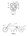
- FIG. 7 a schematic sectional view of an alternate rear wheel assembly for a motorcycle comprising a pair of tires of FIG. 4 mounted on an axle with a gap between the right and left tires;
- FIG. 8 is a schematic side view of a motorcycle apparatus comprising the rear tire and wheel apparatus of FIG. 3 or FIG. 6 ;
- FIG. 9 is a schematic perspective view of an alternate apparatus where the frame member of the motorcycle is attached to outer ends of the axle of the rear wheel assembly.
- FIGS. 1 and 2 illustrate an embodiment of an inflatable tire 1 of the present invention.
- the tire 1 comprises a first bead 3 A and a second bead 3 B adapted to be mounted on a rim 2 , such as that shown beside the tire 1 in FIG. 2 .
- a first sidewall 5 A extends upward from the first bead 3 A to a first edge 7 A of a substantially horizontal tread face 7 located substantially directly above the first bead 5 A.
- a second sidewall 5 B extends upward from the second bead 3 B and then curves toward a second edge 7 B of the tread face such that a curved tire surface 9 is provided between the second bead 3 B and the second edge 7 B of the tread face 7 .
- upward is used herein in the sense that the sidewalls 5 A, 5 B extend outward from the beads 3 A, 3 B, and “upward” (and downward for that matter) in the sectional drawings.
- the width TW of the tread face 7 could vary, but in any event the width TW will be less than half of a distance BW between the first and second beads 3 A, 3 B in order to provide a sufficiently long curved tire surface 9 .
- the illustrated curved tire surface 9 is curved to approximately follow the radius of a circle.
- FIG. 3 schematically illustrates a pair of tires 1 mounted on an axle 11 with a gap 13 between the right tire 1 R and the left tire 1 L.
- FIG. 4 schematically illustrates an alternate embodiment of the tire 101 of the invention where the first bead 103 A has a diameter DA that is larger than a diameter DB of the second bead 103 B such that the second sidewall 105 B extends upward substantially the same distance WB as the first sidewall WA before the second sidewall 105 curves toward the second edge 107 B of the tread face 107 . It is contemplated that having the sidewalls 105 A, 105 B thus balanced and configured may improve the dynamic performance of the tire 101 .
- FIG. 8 A rear tire and wheel apparatus 20 for a motorcycle is illustrated in FIG. 8 mounted on a motorcycle.
- the apparatus 20 comprises, as schematically illustrated in FIG. 3 , a right wheel 21 R comprising a right tire 1 R as in FIG. 2 mounted to a right rim 2 R.
- the right wheel 21 R is mounted on the axle 11 such that the first sidewall 5 A of the right tire 1 R is on a left side of the right wheel 21 R.
- a left wheel 21 L comprises a left tire 1 L as in FIG. 2 mounted to a left rim 2 L.
- the left wheel 21 L mounted on the axle 11 such that the first sidewall 5 A of the left tire 1 L is on a right side of the left wheel 21 L.
- the gap 13 is thus defined between first sidewalls 5 A of the right and left tires 1 R, 1 L, and the second sidewalls 5 B thereof are on the outside of the apparatus 20 , and the curved tire surfaces 9 of each tire 1 R, 1 L are on the outside of the apparatus 20 .
- the right and left wheels 21 R, 21 L are thus rotatably mounted to the rigid axle 11 such that they rotate about the same rotational axis, and move together as the axle 11 moves.
- the right and left tires 21 R, 21 L are configured such that when the motorcycle is oriented in a substantially vertical position as illustrated in FIG. 3 , tread faces 7 of the right and left wheels 21 R, 21 L are on the ground surface 23 , and such that when the motorcycle is in a leaning position to the left, as illustrated in FIG. 5 , the right wheel and tire 1 R are above the ground surface 23 , and the left tire 1 L essentially rolls over onto the curved tire surface 9 of the left tire 1 L and the motorcycle is supported on the curved tire surface 9 of the left tire 1 L.
- the motorcycle rides on the curved tire surface 9 and the motorcycle maneuvers much like a conventional motorcycle.
- a drive 25 extends through the gap 13 to the axle 11 to rotate the right and left wheels 21 R, 21 L and drive a motorcycle to which the apparatus 20 is attached.
- the drive 25 will typically comprises a chain or belt 27 extending through the gap 13 and engaging a sprocket or pulley 29 on the axle 11 .
- the drive 25 can comprise a driveshaft 31 extending through the gap 13 and driving a gear box 33 on the axle 11 .
- the embodiment of FIG. 7 shows the tires 101 of FIG. 4 where the first bead 103 A of the right and left tires 101 A, 101 B has a diameter larger than the second bead 103 B of the right and left tires, and wherein the right and left rims 102 R, 102 L are dished to define corresponding right and left recesses 35 R, 35 L beside the gap 13 .
- the gear box 33 occupies the right and left recesses 35 R, 35 L.
- the dished rims 102 R, 102 L provide increased room to mount the gear box 33 on the axle 11 .
- FIG. 8 schematically illustrates a motorcycle apparatus 40 comprising the rear tire and wheel apparatus 20 of described above and a frame member 41 attached to the axle 11 of the apparatus 20 at a rear end thereof.
- the frame member 41 is pivotally attached to the motorcycle front portion 43 about a substantially horizontal pivot axis PA oriented substantially perpendicular to a motorcycle operating travel direction T.
- the rear end of the frame member 41 extends through the gap and is attached to a middle section of the axle 11 .
- a bias element 45 will be provided to exert a downward bias force BF on the frame member 41 relative to the motorcycle front portion 43 to provide a suspension such as in a conventional motorcycle.
- FIG. 9 illustrates an alternate embodiment where the rear end of the frame member 241 is attached to corresponding right and left ends of the axle 211 of the apparatus 220 .
- the front end of the frame member 241 is pivotally attached to the motorcycle front portion about a substantially horizontal pivot axis PA′.
Landscapes
- Engineering & Computer Science (AREA)
- Mechanical Engineering (AREA)
- Tires In General (AREA)
- Axle Suspensions And Sidecars For Cycles (AREA)
Abstract
Description
Claims (18)
Applications Claiming Priority (2)
| Application Number | Priority Date | Filing Date | Title |
|---|---|---|---|
| CA002610623A CA2610623A1 (en) | 2007-11-15 | 2007-11-15 | Split rear tire for motorcycle |
| CA2610623 | 2007-11-15 |
Publications (2)
| Publication Number | Publication Date |
|---|---|
| US20090126841A1 US20090126841A1 (en) | 2009-05-21 |
| US8327896B2 true US8327896B2 (en) | 2012-12-11 |
Family
ID=40639526
Family Applications (1)
| Application Number | Title | Priority Date | Filing Date |
|---|---|---|---|
| US12/272,039 Expired - Fee Related US8327896B2 (en) | 2007-11-15 | 2008-11-17 | Split rear wheel assembly for a motorcycle |
Country Status (2)
| Country | Link |
|---|---|
| US (1) | US8327896B2 (en) |
| CA (2) | CA2610623A1 (en) |
Citations (12)
| Publication number | Priority date | Publication date | Assignee | Title |
|---|---|---|---|---|
| US552984A (en) * | 1896-01-14 | Bicycle-wheel | ||
| US1160323A (en) * | 1914-11-17 | 1915-11-16 | Joseph I Richards | Vehicle wheel-tire. |
| CH564435A5 (en) * | 1973-07-24 | 1975-07-31 | Bolliger Rene M | Adaptable wheel for differing road conditions - has two tyes of different design or special double tyre on wheel rim |
| US4003443A (en) | 1975-07-31 | 1977-01-18 | Gordon Neal Boughers | Multiple wheel motorcycle suspension and drive system |
| DE4204642C1 (en) * | 1992-02-15 | 1993-07-08 | Viscodrive Gmbh, 5204 Lohmar, De | Drive arrangement for motor vehicle with drive shaft - has twin wheels, one wheel to be coupled via viscous coupling to constantly driven wheel |
| WO1999050133A1 (en) | 1998-03-31 | 1999-10-07 | Nemeth Janos | Motorcycle construction |
| EP1086833A1 (en) * | 1999-09-24 | 2001-03-28 | Hollandse Bandenmarkt Internationaal B.V. | Tyre system |
| JP2001088502A (en) * | 1999-09-20 | 2001-04-03 | Bridgestone Corp | Assembly of tire and wheel |
| US6415837B1 (en) * | 1998-08-12 | 2002-07-09 | Daimlerchrysler Ag | Pneumatic tire for wheels of multiple-track vehicles |
| EP1238824A1 (en) * | 2001-03-06 | 2002-09-11 | M.B.F. S.r.l. | An improved wheel for agricultural use |
| US6733088B2 (en) * | 2001-10-15 | 2004-05-11 | Douglas B. Elkow | Variable-diameter wheel apparatus for motor vehicles |
| CN200942680Y (en) * | 2006-02-05 | 2007-09-05 | 毛立荣 | Balanced type load-carrying carriage wheel |
-
2007
- 2007-11-15 CA CA002610623A patent/CA2610623A1/en not_active Abandoned
-
2008
- 2008-10-28 CA CA2642175A patent/CA2642175C/en active Active
- 2008-11-17 US US12/272,039 patent/US8327896B2/en not_active Expired - Fee Related
Patent Citations (12)
| Publication number | Priority date | Publication date | Assignee | Title |
|---|---|---|---|---|
| US552984A (en) * | 1896-01-14 | Bicycle-wheel | ||
| US1160323A (en) * | 1914-11-17 | 1915-11-16 | Joseph I Richards | Vehicle wheel-tire. |
| CH564435A5 (en) * | 1973-07-24 | 1975-07-31 | Bolliger Rene M | Adaptable wheel for differing road conditions - has two tyes of different design or special double tyre on wheel rim |
| US4003443A (en) | 1975-07-31 | 1977-01-18 | Gordon Neal Boughers | Multiple wheel motorcycle suspension and drive system |
| DE4204642C1 (en) * | 1992-02-15 | 1993-07-08 | Viscodrive Gmbh, 5204 Lohmar, De | Drive arrangement for motor vehicle with drive shaft - has twin wheels, one wheel to be coupled via viscous coupling to constantly driven wheel |
| WO1999050133A1 (en) | 1998-03-31 | 1999-10-07 | Nemeth Janos | Motorcycle construction |
| US6415837B1 (en) * | 1998-08-12 | 2002-07-09 | Daimlerchrysler Ag | Pneumatic tire for wheels of multiple-track vehicles |
| JP2001088502A (en) * | 1999-09-20 | 2001-04-03 | Bridgestone Corp | Assembly of tire and wheel |
| EP1086833A1 (en) * | 1999-09-24 | 2001-03-28 | Hollandse Bandenmarkt Internationaal B.V. | Tyre system |
| EP1238824A1 (en) * | 2001-03-06 | 2002-09-11 | M.B.F. S.r.l. | An improved wheel for agricultural use |
| US6733088B2 (en) * | 2001-10-15 | 2004-05-11 | Douglas B. Elkow | Variable-diameter wheel apparatus for motor vehicles |
| CN200942680Y (en) * | 2006-02-05 | 2007-09-05 | 毛立荣 | Balanced type load-carrying carriage wheel |
Also Published As
| Publication number | Publication date |
|---|---|
| CA2610623A1 (en) | 2009-05-15 |
| US20090126841A1 (en) | 2009-05-21 |
| CA2642175A1 (en) | 2009-05-15 |
| CA2642175C (en) | 2015-02-10 |
Similar Documents
| Publication | Publication Date | Title |
|---|---|---|
| US9981703B2 (en) | Track system | |
| US20060284484A1 (en) | Endless track for high speed multi-terrain vehicles | |
| CA2374657A1 (en) | Atv track conversion | |
| FR2983780A1 (en) | VARIABLE CHANNEL ROLLER BEARING | |
| JP5475420B2 (en) | Pneumatic tires for motorcycles | |
| CA2149715A1 (en) | Tire tread | |
| JP5762367B2 (en) | Transport vehicle | |
| JP4307153B2 (en) | 4 wheel drive electric wheelchair | |
| US7921942B2 (en) | Amphibious all terrain vehicle with track assemblies | |
| JP5919283B2 (en) | Device for preventing slipping of a vehicle equipped with wheels | |
| US8327896B2 (en) | Split rear wheel assembly for a motorcycle | |
| EP1179441B1 (en) | Tyre with asymmetric belt structure and method of mounting said tyre on a vehicle | |
| JPH0617602Y2 (en) | Asymmetric tire | |
| JP5507483B2 (en) | Vehicle propulsion device | |
| CA2887839C (en) | Track system | |
| JPH09109947A (en) | Triangle crawler and crawler car | |
| JP2007537792A (en) | Ski motorbike | |
| US6863462B1 (en) | Apparatus for optimizing the stiffness of an axle | |
| JP3734875B2 (en) | Coreless rubber crawler travel device | |
| JP3967939B2 (en) | Radial tire for ATV | |
| JP6250757B1 (en) | Rough terrain vehicle equipped with rubber crawler travel device | |
| EP3946977B1 (en) | Tread for an agricultural vehicle | |
| EP0016686A1 (en) | Vehicle tyre | |
| CN208021571U (en) | Track drive turns to chassis | |
| WO2017181543A1 (en) | Wheel frame installed on toy car and track toy car |
Legal Events
| Date | Code | Title | Description |
|---|---|---|---|
| ZAAA | Notice of allowance and fees due |
Free format text: ORIGINAL CODE: NOA |
|
| ZAAB | Notice of allowance mailed |
Free format text: ORIGINAL CODE: MN/=. |
|
| STCF | Information on status: patent grant |
Free format text: PATENTED CASE |
|
| FPAY | Fee payment |
Year of fee payment: 4 |
|
| FEPP | Fee payment procedure |
Free format text: MAINTENANCE FEE REMINDER MAILED (ORIGINAL EVENT CODE: REM.); ENTITY STATUS OF PATENT OWNER: SMALL ENTITY |
|
| FEPP | Fee payment procedure |
Free format text: 7.5 YR SURCHARGE - LATE PMT W/IN 6 MO, SMALL ENTITY (ORIGINAL EVENT CODE: M2555); ENTITY STATUS OF PATENT OWNER: SMALL ENTITY |
|
| MAFP | Maintenance fee payment |
Free format text: PAYMENT OF MAINTENANCE FEE, 8TH YR, SMALL ENTITY (ORIGINAL EVENT CODE: M2552); ENTITY STATUS OF PATENT OWNER: SMALL ENTITY Year of fee payment: 8 |
|
| FEPP | Fee payment procedure |
Free format text: MAINTENANCE FEE REMINDER MAILED (ORIGINAL EVENT CODE: REM.); ENTITY STATUS OF PATENT OWNER: SMALL ENTITY |
|
| LAPS | Lapse for failure to pay maintenance fees |
Free format text: PATENT EXPIRED FOR FAILURE TO PAY MAINTENANCE FEES (ORIGINAL EVENT CODE: EXP.); ENTITY STATUS OF PATENT OWNER: SMALL ENTITY |
|
| STCH | Information on status: patent discontinuation |
Free format text: PATENT EXPIRED DUE TO NONPAYMENT OF MAINTENANCE FEES UNDER 37 CFR 1.362 |
|
| FP | Lapsed due to failure to pay maintenance fee |
Effective date: 20241211 |