US8325331B2 - Method for obtaining incident angle - Google Patents
Method for obtaining incident angle Download PDFInfo
- Publication number
- US8325331B2 US8325331B2 US12/568,173 US56817309A US8325331B2 US 8325331 B2 US8325331 B2 US 8325331B2 US 56817309 A US56817309 A US 56817309A US 8325331 B2 US8325331 B2 US 8325331B2
- Authority
- US
- United States
- Prior art keywords
- icon
- distance
- incident angle
- light
- obtaining
- Prior art date
- Legal status (The legal status is an assumption and is not a legal conclusion. Google has not performed a legal analysis and makes no representation as to the accuracy of the status listed.)
- Expired - Fee Related, expires
Links
- 238000000034 method Methods 0.000 title claims abstract description 29
- 238000004891 communication Methods 0.000 description 15
- 229920003023 plastic Polymers 0.000 description 9
- 239000004033 plastic Substances 0.000 description 9
- 238000004519 manufacturing process Methods 0.000 description 6
- 238000007373 indentation Methods 0.000 description 3
- 238000012986 modification Methods 0.000 description 2
- 230000004048 modification Effects 0.000 description 2
- 230000000007 visual effect Effects 0.000 description 2
- 230000003993 interaction Effects 0.000 description 1
- 238000007620 mathematical function Methods 0.000 description 1
Images


Classifications
-
- H—ELECTRICITY
- H04—ELECTRIC COMMUNICATION TECHNIQUE
- H04M—TELEPHONIC COMMUNICATION
- H04M1/00—Substation equipment, e.g. for use by subscribers
- H04M1/02—Constructional features of telephone sets
- H04M1/22—Illumination; Arrangements for improving the visibility of characters on dials
-
- G—PHYSICS
- G09—EDUCATION; CRYPTOGRAPHY; DISPLAY; ADVERTISING; SEALS
- G09F—DISPLAYING; ADVERTISING; SIGNS; LABELS OR NAME-PLATES; SEALS
- G09F13/00—Illuminated signs; Luminous advertising
- G09F13/04—Signs, boards or panels, illuminated from behind the insignia
-
- H—ELECTRICITY
- H04—ELECTRIC COMMUNICATION TECHNIQUE
- H04M—TELEPHONIC COMMUNICATION
- H04M1/00—Substation equipment, e.g. for use by subscribers
- H04M1/72—Mobile telephones; Cordless telephones, i.e. devices for establishing wireless links to base stations without route selection
- H04M1/724—User interfaces specially adapted for cordless or mobile telephones
- H04M1/72469—User interfaces specially adapted for cordless or mobile telephones for operating the device by selecting functions from two or more displayed items, e.g. menus or icons
Definitions
- the present invention relates to a method for obtaining an angle, and more particularly to a method for obtaining an incident angle.
- GUI graphical user interface
- the graphical user interface is an interface for interaction between the user and the electronic device such as a computer, an MP3 player, a household appliance, etc.
- the graphical user interface provides various icons, symbols, word interfaces, or a combination thereof as a visual indicator for the user to understand the associated information of the electronic device currently in use.
- the graphical user interface configured on the electronic device in the market uses an object, a picture or a particular mark as the icon or symbol, which relates to an event currently performed in the electronic device or the information of the event.
- FIG. 1 shows the panel with a graphical user interface configured on a network communication device in the prior art.
- the network communication device 1 includes a panel 10 with a graphical user interface. Through the panel 10 with the graphical user interface, the user can understand the current operating statuses of the network communication device 1 or perform the required function for the network communication device 1 .
- the graphical user interface on the panel 10 includes a first icon 110 , a second icon 111 , a third icon 112 , a fourth icon 113 and a fifth icon 114 .
- the first icon 110 represents an electronic mail
- the second icon 111 represents a wireless network
- the third icon 112 represents a 3G network
- the fourth icon 113 represents the internet
- the fifth icon 114 represents the power supply.
- FIG. 2 shows the icons with different types of indentations formed at the back of the panel made of plastics.
- the icons with different types of indentations formed at the back of the panel 10 are identical to the icons formed at the front thereof.
- FIG. 3 shows the icon representing an electronic mail.
- the icon 110 representing an electronic mail has four triangular protrusions. These protrusions are formed by being processed with the computer numerical control (CNC) step in the plastic mold manufacturing process.
- CNC computer numerical control
- a plurality of red light-emitting diodes are disposed for generating light to project on the corresponding icons, thereby showing the statuses of the network communication device 1 .
- FIG. 4 shows the structural relationship between the red light-emitting diodes and the icons.
- five red light-emitting diodes 101 are disposed under the five icons 110 , 111 , 112 , 113 , 114 by a predetermined height.
- the draft angle is an inclined angle designed at the inner and the outer sides of the edges of the plastic product for facilitating it to be drawn out from the mold.
- FIG. 5 shows how the incident angle ⁇ i is defined.
- the incident angle ⁇ i is formed at the inner side of the edge of each protrusion 5 of the icon 110 representing an electronic mail.
- the incident angle ⁇ i is the angle defined by the intersection of an optic axis (op), which is formed between the inner side of the edge of the protrusion 5 of the icon 110 and the red light-emitting diode 101 , and a normal (N).
- the draft angle is equal to or larger than the incident angle ⁇ i .
- the space for the light-emitting source is constricted, which makes the incident angle ⁇ i smaller. Therefore, when the light from the red light-emitting diode 101 illuminates the surface of the protrusion 5 , the reflecting angle thereof is smaller. This makes the light on the icons 110 , 111 , 112 , 113 , 114 of the panel 10 uneven.
- a method for obtaining an incident angle ⁇ i is provided.
- the method is used in a panel having at least one icon, wherein the at least one icon has a plurality of protrusions, and a light-emitting source is disposed under the at least one icon.
- the method includes steps of obtaining a distance W between two centers of two bottoms of two trenches formed at two sides of one of the plurality of protrusions; obtaining a half of the distance W; obtaining a vertical distance H between the light-emitting source and a center of the distance W; and performing an inverse trigonometric function operation for the half of the distance W over the vertical distance H so as to obtain the incident angle ⁇ i .
- the at least one icon is one selected from a group consisting of a numeral, a character, a symbol and a combination thereof.
- the light-emitting source is a light-emitting diode.
- the distance W is a horizontal distance.
- the distance W is ranged from 6 mm to 12 mm.
- the vertical distance H is ranged from 5 mm to 10 mm.
- ⁇ i Tan ⁇ 1 (W/2)/H.
- the step of performing the inverse trigonometric function operation is performed by using an electronic operational device.
- the incident angle ⁇ i is ranged from 30 degrees to 45 degrees.
- a method for obtaining an incident angle ⁇ i is provided.
- the method is used in a panel having at least one icon, wherein the at least one icon has a plurality of protrusions, and a light-emitting source is disposed under the at least one icon.
- the method includes steps of obtaining a distance W between two centers of two bottoms of two trenches formed at two sides of one of the plurality of protrusions; obtaining a half of the distance W; obtaining a vertical distance H between the light-emitting source and a center of the distance W; and calculating the incident angle ⁇ i based on the half of the distance W and the vertical distance H.
- the at least one icon is one selected from a group consisting of a numeral, a character, a symbol and a combination thereof.
- the light-emitting source is a light-emitting diode.
- the distance W is ranged from 6 mm to 12 mm.
- the vertical distance H is ranged from 5 mm to 10 mm.
- the step of calculating the incident angle ⁇ i is performed by using an electronic operational device.
- the incident angle ⁇ i is ranged from 30 degrees to 45 degrees.
- FIG. 1 shows the panel with a graphical user interface configured on a network communication device in the prior art
- FIG. 2 shows the icons with different types of indentations formed at the back of the panel made of plastics
- FIG. 3 shows the icon representing an electronic mail
- FIG. 4 shows the relationship between the red light-emitting diodes and the icons
- FIG. 5 shows how the incident angle ⁇ i is defined
- FIG. 6 shows the panel with a graphical user interface configured on a network communication device according to the present invention
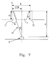
- FIG. 7 is a cross-sectional view of the icon representing an electronic mail according to a preferred embodiment of the present invention.
- FIG. 8 is a cross-sectional view of the icon representing an electronic mail according to another preferred embodiment of the present invention.
- FIG. 6 shows the panel with a graphical user interface configured on a network communication device according to the present invention.
- the graphical user interface provides various icons, symbols, word interfaces, or a combination thereof as a visual indicator for the user to understand the associated information of the network communication device 6 currently in use.
- the graphical user interface on the panel 61 includes a first icon 610 , a second icon 611 , a third icon 612 , a fourth icon 613 and a fifth icon 614 .
- the first icon 610 represents an electronic mail
- the second icon 611 represents a wireless network
- the third icon 612 represents a 3G network
- the fourth icon 613 represents the internet
- the fifth icon 614 represents the power supply.
- the first icon 610 representing an electronic mail is taken as an example to illustrate the present invention.
- FIG. 7 is a cross-sectional view of the icon representing an electronic mail according to a preferred embodiment of the present invention.
- the protrusion 7 is ladder-shaped in a cross-sectional view.
- a first trench 71 with a depth h 1 and a second trench 72 with a depth h 2 are formed at two sides of the protrusion 7 respectively, wherein h 1 is equal to h 2 .
- a plurality of red light-emitting diodes 8 are disposed for generating light to project on the corresponding icons, thereby showing the statuses of the network communication device 6 .
- the draft angle is an inclined angle designed at the inner and the outer sides of the edges of the plastic product for facilitating it to be drawn out from the mold.
- the red light-emitting diodes 8 When the network communication device 6 is powered on, the red light-emitting diodes 8 are switched on to generate red beams.
- An incident angle ⁇ i is formed at the inner side of the edge of each protrusion 7 of the icon 110 representing an electronic mail. As shown in FIG. 7 , the incident angle ⁇ i is the angle defined by the intersection of an optic axis (op′), which is formed between the inner side of the edge of the protrusion 7 of the icon 110 and the red light-emitting diode 8 , and a normal (N′). In the manufacturing process of the plastic product, the draft angle is equal to or larger than the incident angle ⁇ i .
- a mathematical function preferably a trigonometric function such as a sine function, a cosine function, a tangent function, a cotangent function, a secant function or a cosecant function.
- the tangent function is taken as an example to illustrate the present invention. The steps of using the tangent function to calculate the incident angle ⁇ i are described as follows.
- two adjacent sides are required for the tangent function.
- One is a half of the distance W (W/2) between two centers of two bottoms of two trenches formed at two sides of the protrusion 7 , and the other is a vertical distance H between the light-emitting diode 8 and the center of the distance W.
- the distance W is ranged from 6 mm to 12 mm
- the vertical distance H is ranged from 5 mm to 10 mm.
- Equation 1 Assuming that the vertical distance H is 10 mm and a half of the distance W (W/2) is 6 mm, an arctangent function operation is performed for obtaining the incident angle ⁇ i , as shown in Equation 1.
- ⁇ i Tan ⁇ 1 ( W/ 2)/ H Equation 1
- the arctangent function operation can be performed by using an electronic operational device such as a computer or an electronic calculator having a trigonometric function calculating capability, etc.
- the obtained incident angle ⁇ i is 31 degrees.
- the draft angle is equal to or larger than the incident angle ⁇ i , so that it can be designed as 31 degrees or larger than 31 degrees, as shown in FIG. 8 .
- the incident angle ⁇ i of the present invention is ranged from 30 degrees to 45 degrees.
- the incident angle ⁇ i ′ defined by the intersection of the optic axis (op′) and the vertical distance H is an alternate angle of the incident angle ⁇ i . That is to say, the incident angle ⁇ i ′ is equal to the incident angle ⁇ i .
- the incident angle ⁇ i ′ can also be obtained by performing a sine function operation, a cosine function operation, a cotangent function operation, a secant function operation or a cosecant function operation.
Landscapes
- Engineering & Computer Science (AREA)
- Signal Processing (AREA)
- Physics & Mathematics (AREA)
- General Physics & Mathematics (AREA)
- Theoretical Computer Science (AREA)
- Illuminated Signs And Luminous Advertising (AREA)
- Optical Communication System (AREA)
- Planar Illumination Modules (AREA)
Abstract
Description
θi=Tan−1(W/2)/
Claims (16)
Applications Claiming Priority (3)
| Application Number | Priority Date | Filing Date | Title |
|---|---|---|---|
| TW97151500 | 2008-12-30 | ||
| TW97151500A | 2008-12-30 | ||
| TW097151500A TWI390475B (en) | 2008-12-30 | 2008-12-30 | Method for searching for a superior angle of incidence |
Publications (2)
| Publication Number | Publication Date |
|---|---|
| US20100165331A1 US20100165331A1 (en) | 2010-07-01 |
| US8325331B2 true US8325331B2 (en) | 2012-12-04 |
Family
ID=42284559
Family Applications (1)
| Application Number | Title | Priority Date | Filing Date |
|---|---|---|---|
| US12/568,173 Expired - Fee Related US8325331B2 (en) | 2008-12-30 | 2009-09-28 | Method for obtaining incident angle |
Country Status (2)
| Country | Link |
|---|---|
| US (1) | US8325331B2 (en) |
| TW (1) | TWI390475B (en) |
Families Citing this family (1)
| Publication number | Priority date | Publication date | Assignee | Title |
|---|---|---|---|---|
| JP2024005324A (en) * | 2022-06-30 | 2024-01-17 | トヨタ紡織株式会社 | Vehicle display device |
Citations (3)
| Publication number | Priority date | Publication date | Assignee | Title |
|---|---|---|---|---|
| US4803371A (en) * | 1987-09-30 | 1989-02-07 | The Coe Manufacturing Company | Optical scanning method and apparatus useful for determining the configuration of an object |
| CN2227369Y (en) | 1995-06-27 | 1996-05-15 | 宋桂源 | Stereo-advertisement lamp box |
| CN1683968A (en) | 2004-04-12 | 2005-10-19 | 株式会社可乐丽 | Lighting system, image display apparatus using the same and light diffusion plate used therefor |
-
2008
- 2008-12-30 TW TW097151500A patent/TWI390475B/en not_active IP Right Cessation
-
2009
- 2009-09-28 US US12/568,173 patent/US8325331B2/en not_active Expired - Fee Related
Patent Citations (5)
| Publication number | Priority date | Publication date | Assignee | Title |
|---|---|---|---|---|
| US4803371A (en) * | 1987-09-30 | 1989-02-07 | The Coe Manufacturing Company | Optical scanning method and apparatus useful for determining the configuration of an object |
| CN2227369Y (en) | 1995-06-27 | 1996-05-15 | 宋桂源 | Stereo-advertisement lamp box |
| CN1683968A (en) | 2004-04-12 | 2005-10-19 | 株式会社可乐丽 | Lighting system, image display apparatus using the same and light diffusion plate used therefor |
| US7237930B2 (en) * | 2004-04-12 | 2007-07-03 | Kuraray Co., Ltd. | Lighting system image display apparatus using the same and light diffusion plate used therefor |
| US7556393B2 (en) * | 2004-04-12 | 2009-07-07 | Kuraray Co., Ltd. | Lighting system, image display apparatus using the same and light diffusion plate used therefor |
Non-Patent Citations (1)
| Title |
|---|
| Office Action for Chinese Application No. 200910003093.2, dated May 9, 2011. |
Also Published As
| Publication number | Publication date |
|---|---|
| US20100165331A1 (en) | 2010-07-01 |
| TWI390475B (en) | 2013-03-21 |
| TW201025226A (en) | 2010-07-01 |
Similar Documents
| Publication | Publication Date | Title |
|---|---|---|
| JP6073415B2 (en) | Touch panel with fingerprint authentication function | |
| AU2015368103B2 (en) | Window cover and display apparatus having the same and method of manufacturing display apparatus | |
| US10324238B2 (en) | Anti-peep film, method for manufacturing the same and display device | |
| JP2011518385A (en) | System and method for receiving user input via a touch sensor with a display having a flexible backplane | |
| US20100156793A1 (en) | System and Method For An Information Handling System Touchscreen Keyboard | |
| TW201435672A (en) | Touch panel and method of manufacturing the same | |
| WO2022228376A1 (en) | Message processing method and apparatus, and electronic device | |
| CN105321758B (en) | structure of keyboard backlight module | |
| CN102750035B (en) | The determination method and apparatus of display position of cursor | |
| US8325331B2 (en) | Method for obtaining incident angle | |
| TWI619050B (en) | Touch sensor | |
| US9557823B1 (en) | Keyboard customization according to finger positions | |
| US20100033434A1 (en) | Keyboard | |
| CN105913799B (en) | A kind of display screen and terminal | |
| CN203966912U (en) | keyboard backlight | |
| CN205542526U (en) | Keyboard backlight module | |
| US10614152B2 (en) | Exposing formatting properties of content for accessibility | |
| CN115360221A (en) | Display panel and electronic device | |
| CN105718492A (en) | Information processing method and electronic device | |
| Liu et al. | Object stability is determined by the geometric centroid | |
| CN106356213B (en) | Key assembly | |
| Garmon et al. | Contextual influences on shape perception | |
| CN204679992U (en) | Capacitive touch screen | |
| CN101782683A (en) | Method for searching incident angle | |
| Walther et al. | Where to draw the line? |
Legal Events
| Date | Code | Title | Description |
|---|---|---|---|
| AS | Assignment |
Owner name: ARCADYAN TECHNOLOGY CORP.,TAIWAN Free format text: ASSIGNMENT OF ASSIGNORS INTEREST;ASSIGNORS:CHEN, SHENG CHUNG;WU, CHIN YI;REEL/FRAME:023291/0129 Effective date: 20090922 Owner name: ARCADYAN TECHNOLOGY CORP., TAIWAN Free format text: ASSIGNMENT OF ASSIGNORS INTEREST;ASSIGNORS:CHEN, SHENG CHUNG;WU, CHIN YI;REEL/FRAME:023291/0129 Effective date: 20090922 |
|
| STCF | Information on status: patent grant |
Free format text: PATENTED CASE |
|
| FPAY | Fee payment |
Year of fee payment: 4 |
|
| FEPP | Fee payment procedure |
Free format text: MAINTENANCE FEE REMINDER MAILED (ORIGINAL EVENT CODE: REM.); ENTITY STATUS OF PATENT OWNER: LARGE ENTITY |
|
| LAPS | Lapse for failure to pay maintenance fees |
Free format text: PATENT EXPIRED FOR FAILURE TO PAY MAINTENANCE FEES (ORIGINAL EVENT CODE: EXP.); ENTITY STATUS OF PATENT OWNER: LARGE ENTITY |
|
| STCH | Information on status: patent discontinuation |
Free format text: PATENT EXPIRED DUE TO NONPAYMENT OF MAINTENANCE FEES UNDER 37 CFR 1.362 |
|
| FP | Lapsed due to failure to pay maintenance fee |
Effective date: 20201204 |