US8324993B2 - Electromagnetic contact device - Google Patents
Electromagnetic contact device Download PDFInfo
- Publication number
- US8324993B2 US8324993B2 US13/138,926 US201013138926A US8324993B2 US 8324993 B2 US8324993 B2 US 8324993B2 US 201013138926 A US201013138926 A US 201013138926A US 8324993 B2 US8324993 B2 US 8324993B2
- Authority
- US
- United States
- Prior art keywords
- movable core
- movable
- contact point
- driving lever
- point support
- Prior art date
- Legal status (The legal status is an assumption and is not a legal conclusion. Google has not performed a legal analysis and makes no representation as to the accuracy of the status listed.)
- Expired - Fee Related
Links
Images


Classifications
-
- H—ELECTRICITY
- H01—ELECTRIC ELEMENTS
- H01H—ELECTRIC SWITCHES; RELAYS; SELECTORS; EMERGENCY PROTECTIVE DEVICES
- H01H50/00—Details of electromagnetic relays
- H01H50/64—Driving arrangements between movable part of magnetic circuit and contact
- H01H50/643—Driving arrangements between movable part of magnetic circuit and contact intermediate part performing a rotating or pivoting movement
-
- H—ELECTRICITY
- H01—ELECTRIC ELEMENTS
- H01H—ELECTRIC SWITCHES; RELAYS; SELECTORS; EMERGENCY PROTECTIVE DEVICES
- H01H50/00—Details of electromagnetic relays
- H01H50/02—Bases; Casings; Covers
- H01H50/04—Mounting complete relay or separate parts of relay on a base or inside a case
- H01H50/041—Details concerning assembly of relays
- H01H50/045—Details particular to contactors
-
- H—ELECTRICITY
- H01—ELECTRIC ELEMENTS
- H01H—ELECTRIC SWITCHES; RELAYS; SELECTORS; EMERGENCY PROTECTIVE DEVICES
- H01H50/00—Details of electromagnetic relays
- H01H50/16—Magnetic circuit arrangements
- H01H50/18—Movable parts of magnetic circuits, e.g. armature
- H01H50/20—Movable parts of magnetic circuits, e.g. armature movable inside coil and substantially lengthwise with respect to axis thereof; movable coaxially with respect to coil
Definitions
- the invention relates to an electromagnetic contact device, and more specifically relates to a driving lever which transmits attraction movement and release movement of a movable core of an electromagnet to a movable contact point support.
- Patent Reference 1 is for example known as an electromagnetic contact device.
- an electromagnet In the electromagnetic contact device of this Patent Reference 1, an electromagnet, a movable contact point support arranged parallel to the electromagnet, a return spring which urges the movable contact point support toward an initial position, and a driving lever which transmits attraction movement and release movement of the electromagnet to the movable contact point support, are accommodated within a case.
- the movable contact point support comprises a plurality of movable contact points, which moves against the return spring to perform open or close operations with fixed contact points arranged within the case in opposition to each of the movable contact points.
- the electromagnet comprises an excitation coil, a fixed core, and a movable core arranged in opposition to and capable of contacting and separating from the fixed core.
- the center portion in the length direction of the driving lever is axially supported via a pin within the case, one end is engaged with the movable contact point support, and another end is engaged with the movable core.
- the driving lever is conjoined with the case via the pin, so that there is a problem that the time required for driving lever assembly is increased.
- the point of action of the driving lever transmitting movement of the movable core to the movable contact point support does not coincide with the line of action (line extending from the axial line) of the return spring applying a urging force to the movable contact point support, so there is a concern that a moment may be imparted to the moving movable contact point support, and there is a concern that sliding friction with the case may increase.
- This invention focuses on the above unresolved problems of examples of the prior art, and has as an object of providing an electromagnetic contact device which enables removal, by normal operation, of the problem of light adhesion of contact point portions due to the flow of excessive current, and enables easy assembly of the driving lever linking the movable contact point support and the electromagnet, and in which moreover the movable contact point support can be operated without the occurrence of a moment.
- the electromagnetic contact device of one embodiment has a case accommodating an electromagnet having a movable core for attraction movement and release movement, a movable contact point support moving between an initial position and an operation position in parallel with a moving direction of the movable core, a return spring urging this movable contact point support toward the initial position, and a driving lever which is engaged with the movable core and the movable contact point support, and transmits the attraction movement of the movable core to the movable contact point support as a moving force toward the operation position.
- the electromagnetic contact device is configured such that a lever holding portion is formed in an inner wall of an extinction cover, and by mounting this extinction cover on the case and having the lever holding portion to axially support one end of the driving lever, the driving lever is accommodated such that another end thereof engaged with the movable core and movable contact point support rotates with the one end as a rotation support point.
- the movable contact point support halts midway during release, the release movement due to inertial force of the movable core is transmitted to the movable contact point support via the driving lever as a moving force toward the initial position.
- the release movement due to inertial force of the movable, core is a movement of the movable contact point support, wherein the movable contact point support pressed to the initial position side by the urging force of the return spring is transmitted via the driving lever to the movable core, so that the movable core performs release movement.
- the movable contact point support is halted, the movable core performs release movement due to the force of inertia.
- the electromagnetic contact device of this embodiment By means of the electromagnetic contact device of this embodiment, a pin or other rotation support member fixed in the case, as in a structure of the prior art, is unnecessary, so that the number of components required for assembly of the driving lever can be reduced. Further, even when the movable contact point support halts midway during release due to slight adhesion of the movable contact points and fixed contact points caused by flow of an excessive current, release movement due to inertial force of the movable core is transmitted via the driving lever to the movable contact point support as a moving force directed toward the initial position, so that the slightly adhering movable contact points and fixed contact points are immediately pulled apart, and slight adhesion of contact points can be removed in normal operation of the electromagnetic contact device.
- a point of action of the driving lever which transmits the attraction movement of the movable core to the movable contact point support as the moving force, is positioned on a line extending from an axial line of the return spring.
- the electromagnetic contact device of this embodiment By means of the electromagnetic contact device of this embodiment, a moment does not act on the movable contact point support to which a force is transmitted from the point of action of the return spring and driving lever, the sliding friction of the movable contact point support with the case interior can be reduced, and the durability of the movable contact point support can be improved.
- a movable core engaging hole is formed in the movable core, and another end of the driving lever is inserted into and engaged with this movable core engaging hole, and in the vicinity of an inner face of the movable core engaging hole with which another end is engaged, a first-contact portion which abuts the an other end before the inner face is formed when the movable core performs the release movement due to the inertial force.
- the shape of a tip portion of the driving lever inserted into the movable core engaging hole is made a narrow tip shape with an area smaller than an opening area of the movable core engaging hole.
- another end of the driving lever is bent in the moving direction of the movable core and inserted into the movable core engaging hole to be in proximity to the inner face of the movable core engaging hole positioned in the moving direction of the movable core.
- another end of the driving lever is in proximity to the inner face of the movable core engaging hole positioned in the moving direction of the movable core, so that attraction movement and release movement due to inertial force of the movable core are immediately transmitted to the movable contact point support.
- the lever holding portion formed in the inner wall of the extinction cover is a recess supported by entering the one end of the driving lever.
- the one end of the driving lever can be axially supported so as to become a rotation support point by the recess of a simple structure formed in an inner wall of the extinction cover.
- an electromagnetic contact device of this invention By means of an electromagnetic contact device of this invention, a pin or other rotation holding member fixed in the case, as in a structure of the prior art, is unnecessary, so that the components necessary for assembly of the driving lever can be reduced. Further, even when the movable contact point support halts midway during release due to slight adhesion of contact point portions caused by the flow of excessive current, the release movement of the movable core due to inertial force is transmitted to the movable contact point support via the driving lever as a moving force directed toward the initial position, and the slightly adhering contact point portions are immediately pulled apart, so that slight adhesion of contact points can be removed in normal operation of the electromagnetic contact device.
- FIG. 1 is a perspective view showing the electromagnetic contact device of a first embodiment of the invention
- FIG. 2 is an exploded perspective view showing constituent members of an electromagnetic contact device
- FIG. 3 is a cross-sectional view showing the initial state of an electromagnetic contact device
- FIG. 4 is a simplified view showing the state of rotation of a driving lever and movement of a movable contact point support to an operation position, when the movable core of an electromagnetic contact device performs attraction movement;
- FIG. 5 is a simplified view showing rotation of the driving lever and release movement of the movable core when the movable contact point support of an electromagnetic contact device moves to the initial position due to the urging force of the return spring;
- FIG. 6 is a simplified view showing the state of rotation of the driving lever and movement of the movable contact point support to the initial position when the movable core of an electromagnetic contact device performs-release movement due to inertial force;
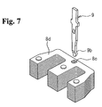
- FIG. 7 is a perspective view showing the structure of the movable core and the structure conjoining with the driving lever, comprised by an electromagnetic contact device;
- FIG. 8 shows the structure of a movable core engaging hole provided in the movable core comprising an electromagnetic contact device
- FIG. 9 shows the state of another end of the driving lever comprising an electromagnetic contact device.
- the electromagnetic contact device 1 of this embodiment comprises a lower case 3 and an upper case 4 , formed from a synthetic resin having insulating properties.
- terminal portions 10 a to 10 d each having contact points, and the coil terminal 11 of an electromagnet are arranged.
- an extinction cover 5 which accommodates in a sealed state a movable contact point support 7 a , described below, and a terminal cover 6 which covers the terminal portions 10 a to 10 d each having contact points and the coil terminal 11 of the electromagnet, are mounted.
- the movable contact point support 7 a comprises a movable contact point support base 7 a 1 , and a movable contact point support cover 7 a 2 which adheres and joins to this movable contact point support base 7 a 1 ; on the movable contact point support base 7 a 1 , a plurality of sets of combinations of movable contact points 7 a 3 and contact springs 7 a 4 are mounted. Further, on the terminal portions 10 a to 10 d each having contact points mounted on the upper case 4 are provided contact point pieces 12 ; fixed contact points (not shown) provided on these contact point pieces 12 oppose each of the movable contact points 7 a 3 .
- an AC-operation type electromagnet 8 as shown in FIG. 2 .
- This electromagnet 8 comprises a coil frame 8 b which an excitation coil 8 a is wound around (see FIG. 3 ); a fixed core 8 c inserted into a hollow portion of the coil frame 8 b and fixed to a side wall of the lower case 3 ; a movable core 8 d arranged in opposition to and capable of contacting and separating from the fixed core 8 c , and inserted into a hollow portion of the coil frame 8 b ; and a pair of coil terminals 11 formed integrally and mutually separated on the end of the coil frame 8 b at which the movable core 8 d is arranged.
- the pair of coil terminals 11 is arranged in a row with the terminal portions 10 a to 10 d each of which has contact points mounted within the upper case 4 .
- the movable contact point support 7 a accommodated within the upper case 4 and electromagnet 8 accommodated within the lower case 3 are arranged such that the moving direction of open and close operation of the movable contact point support 7 a and the moving direction of the movable core 8 d (attraction movement direction and release movement direction) are parallel, and in addition the return spring 7 b is arranged so as to act with a urging force in the direction causing the movable contact point support 7 a to return to the initial position.
- a driving lever 9 conjoined with one end of the movable contact point 7 a separated from the return spring 7 b and with the movable core 8 d , is extended and accommodated between the lower case 3 and the upper case 4 , as shown in FIG. 3 .
- the driving lever 9 is a plate-shape member, and as shown in FIG. 2 , one end in the length direction is a rotation support point portion 9 a , and a movable core conjoining portion 9 b is formed on another end in the length direction; in the center in the length direction a movable contact point support conjoining portion 9 c is provided, and a pair of supported portions 9 d is formed at a position closer to the side of the rotation support point portion 9 a than the movable contact point support conjoining portion 9 c.
- the movable core conjoining portion 9 b of the driving lever 9 is inserted from above into and conjoined with a conjoining hole 8 e formed in the movable core 8 d.
- the conjoining hole 8 e is formed as a hexagonal hole in which a first inner face 8 e 1 provided in one moving direction of the movable core 8 d has an inside width (width perpendicular to the movement direction) smaller than a second inner face 8 e 2 provided in the other movement direction of the movable core 8 d , and with an inclined face 8 e 3 continuous from the first inner face 8 e 1 and inclined on the side of the second inner face 8 e 2 provided.
- the movable core conjoining portion 9 b has a narrow tip portion 9 b 1 formed by gradually narrowing the plate width, and by providing a bent portion 9 b 2 , the width h 2 to the tip portion 9 b 1 is set to a slightly smaller value than the hole width h 1 (see FIG. 8 ) between the first inner face 8 e 1 and the second inner face 8 e 2 of the conjoining hole 8 e.
- the movable contact point support conjoining portion 9 c of the driving lever 9 is provided with a bulging portion, and passes through a lever conjoining hole 7 a 5 which vertically penetrates one side of the movable contact point support 7 a as shown in FIG. 3 .
- a lever conjoining hole 7 a 5 is provided, on the right side in FIG. 3 , a lever engaging wall 7 a 7 which can abut the movable contact point support conjoining portion 9 c.
- the pair of supported portions 9 d of the driving lever 9 protrudes outward from the plate width direction, and as shown in FIG. 3 , when the movable contact point support conjoining portion 9 c passes through the lever conjoining hole 7 a 5 of the movable contact point support 7 a , rotatably abut the upper-end face 7 a 6 of the movable contact point support 7 a.
- the rotation support point portion 9 a of the driving lever 9 enters a support point recess 5 a provided in the lower face of the extinction cover 5 and rotatably conjoined. And, when the extinction cover 5 is mounted on the upper case 4 , the support point recess 5 a holds the rotation support point portion 9 a of the driving lever 9 , and in addition presses the pair of supported portions 9 d against the upper-end face 7 a 6 of the movable contact point support 7 a.
- the movable contact point support conjoining portion 9 c of the driving lever 9 which is conjoined with the lever conjoining hole 7 a 5 of the movable contact point support 7 a is positioned on the line of action of the return spring 7 b (the line extending from the axial line P), as shown in FIG. 3 .
- the case of this invention corresponds to the lower case 3
- the case of this invention corresponds to the upper case 4
- the lever holding portion and recess of this invention correspond to the support point recess 5 a
- the movable core engaging hole of this invention corresponds to the conjoining hole 8 e
- the inner faces of the movable core engaging hole of this invention correspond to the first inner face 8 e 1 and second inner face 8 e 2
- the first-contact portion of this invention corresponds to the inclined face 8 e 3
- the one end portion of the driving lever of this invention corresponds to the rotation support point portion 9 a
- another end portion of the driving lever of this invention corresponds to the movable core conjoining portion 9 b
- the narrow tip of this invention corresponds to the narrow tip portion 9 b 1 .
- the excitation coil 8 a of the electromagnet 8 When in an electromagnetic contact device 1 of this embodiment, the excitation coil 8 a of the electromagnet 8 is in the non-excited state, then as shown in FIG. 3 , an attractive force does not act between the fixed core 8 c and the movable core 8 d , and the movable contact point support 7 a is moved to the right in FIG. 3 (hereafter called the initial position of the movable contact point support 7 a ) by the urging force of the return spring 7 b . At this time, the movable contact points 7 a 3 of the a contact points of the movable contact point support 7 a are separated from the fixed contact points, and the movable contact points 7 a 3 of the b contact points are in contact with the fixed contact points.
- the movable contact points 7 a 3 of the a contact points of the movable contact point support 7 a make contact with the fixed contact points, and the movable contact points 7 a 3 of the b contact points are separated from the fixed contact points.
- the movable core conjoining portion 9 b of the driving lever 9 abuts the first inner face 8 e 1 of the conjoining hole 8 e of the movable core 8 d , and the driving lever 9 rotates in the counterclockwise direction with the rotation support point portion 9 a , engaged with the wall on the left side of the support point recess 5 a , as a rotation support point. And, due to the abutting of the lever engaging wall 7 a 7 of the rotation contact point support 7 a on a portion of the driving lever 9 rotating in the counterclockwise direction, an external force toward the initial position is transmitted to the movable contact point support 7 a .
- the rotation support point portion 9 a provided at one end of the driving lever 9 conjoined with the movable core 8 d and movable contact point support 7 a , is rotatably conjoined with the support point recess 5 a provided in the lower face of the extinction cover 5 , in a structure which is freely rotatable with the rotation support point portion 9 a as a rotation support point; a pin or other rotation holding member fixed to the case, as in a structure of the prior art, is unnecessary, so that the number of components necessary for assembly of the driving lever 9 can be reduced.
- the movable contact point support conjoining portion 9 c of the driving lever 9 conjoined with the lever conjoining hole 7 a 5 of the movable contact point support 7 a is positioned on the line of action (line extending from the axial line P) of the return spring 7 b , so that no moment acts on the movable contact point support 7 a to which force is transmitted from the points of action of the return spring 7 b and driving lever 9 , the sliding friction of the movable contact point support 7 a with the inside of the upper case 4 can be reduced, and the durability of the movable contact point support 7 a can be improved.
- an inclined face 8 e 3 is provided in the conjoining hole 8 e of the movable core 8 d on the side in one movement direction, and as shown in FIG. 6 , when the movable core 8 d undergoes release movement due to inertial force, the movable core conjoining portion 9 b comes into contact with the inclined face 8 e 3 before the first inner face 8 e 1 , so that movement responsiveness of the movable contact point support 7 a when the movable core 8 d undergoes release movement due to inertial force can be improved.
- the movable core conjoining portion 9 b of the driving lever 9 comprises a narrow tip portion 9 b 1 , so that operation to insert the movable core conjoining portion 9 b toward the conjoining hole 8 e of the movable core 8 d can easily be performed.
- the width h 2 from the bent portion 9 b 2 to the tip portion 9 b 1 is set to a value slightly smaller than the hole width h 1 between the first inner face 8 e 1 and the second inner face 8 e 2 of the conjoining hole 8 e of the movable core 8 d , and when the movable core 8 d moves in the attraction direction and the release direction, rotation operation of the driving lever 9 is immediately transmitted from the first inner face 8 e 1 or the second inner face 8 e 2 via the movable core conjoining portion 9 b , so that movement responsiveness of the movable contact point support 7 a can be improved.
- the support point recess 5 a formed in the extinction cover 5 envelops and supports the rotation support point portion 9 a which is one end of the driving lever 9 , so that the rotation support point portion 9 a can be axially supported by a simple structure.
- an electromagnetic contact device of this invention is useful for enabling elimination by normal operation of problems of slight adhesion of contact point portions due to the flow of excessive currents, and for the easy assembly of the driving lever which links the movable contact point support and the electromagnet.
Landscapes
- Physics & Mathematics (AREA)
- Electromagnetism (AREA)
- Electromagnets (AREA)
- Arc-Extinguishing Devices That Are Switches (AREA)
- Driving Mechanisms And Operating Circuits Of Arc-Extinguishing High-Tension Switches (AREA)
Abstract
Description
- Patent Reference 1: Japanese Patent Laid-open No. 556-128533 (FIG. 4)
- 1 Electromagnetic contact device
- 3 Lower case
- 4 Upper case
- 5 Extinction cover
- 5 a Support point recess
- 6 Terminal cover
- 7 a Movable contact point support
- 7 a 1 Movable contact point support base
- 7 a 2 Movable contact point support cover
- 7 a 3 Movable contact point
- 7 a 4 Contact spring
- 7 a 5 Lever conjoining hole
- 7 b Return spring
- 7 a 6 Upper-end face
- 7 a 7 Lever engaging wall
- 8 Electromagnet
- 8 a Excitation coil
- 8 b Coil frame
- 8 c Fixed core
- 8 d Movable core
- 8 e Conjoining hole
- 8
e 1 First inner face - 8 e 2 Second inner face
- 8
e 3 Inclined face - 9 Driving lever
- 9 a Rotation support point portion
- 9 b Movable core conjoining portion
- 9
b 1 Tip portion - 9 b 2 Bent portion
- 9 c Movable contact point support conjoining portion
- 9 d Supported portion
- 10 a-10 d Terminal portion
- 11 Coil terminal
- 12 Contact point piece
- P Return spring axial line
Claims (6)
Applications Claiming Priority (3)
| Application Number | Priority Date | Filing Date | Title |
|---|---|---|---|
| JP2009-190587 | 2009-08-20 | ||
| JP2009190587A JP5018844B2 (en) | 2009-08-20 | 2009-08-20 | Magnetic contactor |
| PCT/JP2010/003936 WO2011021334A1 (en) | 2009-08-20 | 2010-06-14 | Electromagnetic contactor |
Publications (2)
| Publication Number | Publication Date |
|---|---|
| US20120139673A1 US20120139673A1 (en) | 2012-06-07 |
| US8324993B2 true US8324993B2 (en) | 2012-12-04 |
Family
ID=43606796
Family Applications (1)
| Application Number | Title | Priority Date | Filing Date |
|---|---|---|---|
| US13/138,926 Expired - Fee Related US8324993B2 (en) | 2009-08-20 | 2010-06-14 | Electromagnetic contact device |
Country Status (5)
| Country | Link |
|---|---|
| US (1) | US8324993B2 (en) |
| EP (1) | EP2469570B1 (en) |
| JP (1) | JP5018844B2 (en) |
| CN (1) | CN102859631B (en) |
| WO (1) | WO2011021334A1 (en) |
Cited By (2)
| Publication number | Priority date | Publication date | Assignee | Title |
|---|---|---|---|---|
| US20160126042A1 (en) * | 2014-10-31 | 2016-05-05 | Lsis Co., Ltd. | Crossbar structure of electromagnetic contactor |
| US20160260564A1 (en) * | 2014-05-20 | 2016-09-08 | Fuji Electric Fa Components & Systems Co., Ltd. | Electromagnetic contactor |
Families Citing this family (2)
| Publication number | Priority date | Publication date | Assignee | Title |
|---|---|---|---|---|
| CN106941056B (en) * | 2017-02-28 | 2018-09-21 | 厦门宏发电力电器有限公司 | A kind of magnetic latching relay with balanced-armature part |
| JP6732155B1 (en) * | 2019-10-18 | 2020-07-29 | 三菱電機株式会社 | Contact switch and auxiliary connection pin |
Citations (21)
| Publication number | Priority date | Publication date | Assignee | Title |
|---|---|---|---|---|
| US1408632A (en) * | 1904-02-19 | 1922-03-07 | Frederick R Parker | Relay |
| US2658961A (en) * | 1952-08-19 | 1953-11-10 | Clarence E Fisher | Relay device |
| US2794882A (en) * | 1945-03-21 | 1957-06-04 | Cutler Hammer Inc | Electric switch operating structure |
| US3277410A (en) * | 1963-09-13 | 1966-10-04 | Telemecanique Electrique | Electro-magnetic relay comprising a number of bridge contacts carried by a sliding bar |
| US3671891A (en) * | 1970-08-31 | 1972-06-20 | Matsushita Electric Works Ltd | Small type electromagnetic contactor |
| US3882435A (en) * | 1974-06-28 | 1975-05-06 | Square D Co | Latch attachment for an electromagnetically operated switching device |
| JPS56128533A (en) | 1980-03-13 | 1981-10-08 | Fuji Electric Co Ltd | Electromagnetic contactor |
| US4490701A (en) * | 1982-08-17 | 1984-12-25 | Sds-Elektro Gmbh | Electromagnetic switchgear comprising a magnetic drive and a contact apparatus placed thereabove |
| US4509026A (en) * | 1981-04-30 | 1985-04-02 | Matsushita Electric Works, Ltd. | Polarized electromagnetic relay |
| JPS62144039A (en) | 1985-12-18 | 1987-06-27 | Ulvac Corp | Helium leak test method and apparatus therefor |
| JPS6448339A (en) | 1987-08-19 | 1989-02-22 | Fuji Electric Co Ltd | Electromagnetic contact device |
| US4916421A (en) * | 1987-10-01 | 1990-04-10 | General Electric Company | Contact arrangement for a current limiting circuit breaker |
| US4947146A (en) * | 1989-03-07 | 1990-08-07 | Matsushita Electric Works, Ltd. | Electromagnetic contactor |
| US5014027A (en) * | 1989-03-24 | 1991-05-07 | Mitsubishi Denki Kabushiki Kaisha | Electromagnetic contactor |
| JPH03110733A (en) | 1989-09-26 | 1991-05-10 | Matsushita Electric Works Ltd | Reversing lever of electromagnetic contactor and its manufacture |
| US5059930A (en) * | 1989-03-29 | 1991-10-22 | Mitsubishi Denki Kabushiki Kaisha | Electromagnetic contactor and fabrication method therefor |
| US5075660A (en) * | 1989-03-24 | 1991-12-24 | Mitsubishi Denki Kabushiki Kaisha | Electromagnetic contractor and fabrication method therefor |
| US5081436A (en) * | 1988-11-22 | 1992-01-14 | Omron Corporation | Electromagnetic relay having an improved terminal structure |
| JPH0686245A (en) | 1992-02-29 | 1994-03-25 | Samsung Electron Co Ltd | Signal processing system |
| US20010045878A1 (en) * | 2000-04-03 | 2001-11-29 | Werner Fausch | Relay |
| US7091805B2 (en) * | 2004-03-15 | 2006-08-15 | Omron Corporation | Electromagnetic relay |
Family Cites Families (3)
| Publication number | Priority date | Publication date | Assignee | Title |
|---|---|---|---|---|
| CH663290A5 (en) * | 1983-11-28 | 1987-11-30 | Sprecher & Schuh Ag | ELECTROMAGNETIC SWITCHING DEVICE. |
| JPH047548Y2 (en) * | 1986-03-06 | 1992-02-27 | ||
| FR2697371B1 (en) * | 1992-10-26 | 1994-11-18 | Telemecanique | Contactor device. |
-
2009
- 2009-08-20 JP JP2009190587A patent/JP5018844B2/en active Active
-
2010
- 2010-06-14 WO PCT/JP2010/003936 patent/WO2011021334A1/en not_active Ceased
- 2010-06-14 US US13/138,926 patent/US8324993B2/en not_active Expired - Fee Related
- 2010-06-14 CN CN201080020145.8A patent/CN102859631B/en not_active Expired - Fee Related
- 2010-06-14 EP EP10809682.7A patent/EP2469570B1/en not_active Not-in-force
Patent Citations (21)
| Publication number | Priority date | Publication date | Assignee | Title |
|---|---|---|---|---|
| US1408632A (en) * | 1904-02-19 | 1922-03-07 | Frederick R Parker | Relay |
| US2794882A (en) * | 1945-03-21 | 1957-06-04 | Cutler Hammer Inc | Electric switch operating structure |
| US2658961A (en) * | 1952-08-19 | 1953-11-10 | Clarence E Fisher | Relay device |
| US3277410A (en) * | 1963-09-13 | 1966-10-04 | Telemecanique Electrique | Electro-magnetic relay comprising a number of bridge contacts carried by a sliding bar |
| US3671891A (en) * | 1970-08-31 | 1972-06-20 | Matsushita Electric Works Ltd | Small type electromagnetic contactor |
| US3882435A (en) * | 1974-06-28 | 1975-05-06 | Square D Co | Latch attachment for an electromagnetically operated switching device |
| JPS56128533A (en) | 1980-03-13 | 1981-10-08 | Fuji Electric Co Ltd | Electromagnetic contactor |
| US4509026A (en) * | 1981-04-30 | 1985-04-02 | Matsushita Electric Works, Ltd. | Polarized electromagnetic relay |
| US4490701A (en) * | 1982-08-17 | 1984-12-25 | Sds-Elektro Gmbh | Electromagnetic switchgear comprising a magnetic drive and a contact apparatus placed thereabove |
| JPS62144039A (en) | 1985-12-18 | 1987-06-27 | Ulvac Corp | Helium leak test method and apparatus therefor |
| JPS6448339A (en) | 1987-08-19 | 1989-02-22 | Fuji Electric Co Ltd | Electromagnetic contact device |
| US4916421A (en) * | 1987-10-01 | 1990-04-10 | General Electric Company | Contact arrangement for a current limiting circuit breaker |
| US5081436A (en) * | 1988-11-22 | 1992-01-14 | Omron Corporation | Electromagnetic relay having an improved terminal structure |
| US4947146A (en) * | 1989-03-07 | 1990-08-07 | Matsushita Electric Works, Ltd. | Electromagnetic contactor |
| US5014027A (en) * | 1989-03-24 | 1991-05-07 | Mitsubishi Denki Kabushiki Kaisha | Electromagnetic contactor |
| US5075660A (en) * | 1989-03-24 | 1991-12-24 | Mitsubishi Denki Kabushiki Kaisha | Electromagnetic contractor and fabrication method therefor |
| US5059930A (en) * | 1989-03-29 | 1991-10-22 | Mitsubishi Denki Kabushiki Kaisha | Electromagnetic contactor and fabrication method therefor |
| JPH03110733A (en) | 1989-09-26 | 1991-05-10 | Matsushita Electric Works Ltd | Reversing lever of electromagnetic contactor and its manufacture |
| JPH0686245A (en) | 1992-02-29 | 1994-03-25 | Samsung Electron Co Ltd | Signal processing system |
| US20010045878A1 (en) * | 2000-04-03 | 2001-11-29 | Werner Fausch | Relay |
| US7091805B2 (en) * | 2004-03-15 | 2006-08-15 | Omron Corporation | Electromagnetic relay |
Cited By (4)
| Publication number | Priority date | Publication date | Assignee | Title |
|---|---|---|---|---|
| US20160260564A1 (en) * | 2014-05-20 | 2016-09-08 | Fuji Electric Fa Components & Systems Co., Ltd. | Electromagnetic contactor |
| US10297407B2 (en) * | 2014-05-20 | 2019-05-21 | Fuji Electric Fa Components & Systems Co., Ltd. | Electromagnetic contactor |
| US20160126042A1 (en) * | 2014-10-31 | 2016-05-05 | Lsis Co., Ltd. | Crossbar structure of electromagnetic contactor |
| US9646790B2 (en) * | 2014-10-31 | 2017-05-09 | Lsis Co., Ltd. | Crossbar structure of electromagnetic contactor |
Also Published As
| Publication number | Publication date |
|---|---|
| CN102859631B (en) | 2014-12-17 |
| US20120139673A1 (en) | 2012-06-07 |
| EP2469570A4 (en) | 2014-04-02 |
| CN102859631A (en) | 2013-01-02 |
| EP2469570A1 (en) | 2012-06-27 |
| JP5018844B2 (en) | 2012-09-05 |
| EP2469570B1 (en) | 2017-04-26 |
| JP2011044284A (en) | 2011-03-03 |
| WO2011021334A1 (en) | 2011-02-24 |
Similar Documents
| Publication | Publication Date | Title |
|---|---|---|
| US9640336B2 (en) | Magnetic latching relay having asymmetrical solenoid structure | |
| US20150022292A1 (en) | Electromagnetic switch and contact position regulating method thereof | |
| US20150054605A1 (en) | Electromagnetic relay | |
| JP5497880B2 (en) | Auxiliary contact mechanism of magnetic contactor | |
| US8324993B2 (en) | Electromagnetic contact device | |
| JP5821354B2 (en) | Auxiliary contact unit of magnetic contactor | |
| CN106062913B (en) | Electromagnetic contactor | |
| WO2014091650A1 (en) | Electromagnetic contactor | |
| CN104704598A (en) | Electromagnetic contactor | |
| JP6030934B2 (en) | Electromagnetic trip device | |
| JP4281251B2 (en) | Electromagnetic relay | |
| US8410877B1 (en) | Electromagnetic contactor and assembly method for the same | |
| CN104364870A (en) | Electrical switching devices and relays comprising ferromagnets or magnetic armatures with tapered sections | |
| TW201913700A (en) | breaker | |
| US11373830B2 (en) | Electromagnetic relay to ensure stable energization even when contact is dissolved | |
| CN103370761A (en) | Electromagnetic relay | |
| WO2020148994A1 (en) | Relay | |
| KR20160003787U (en) | Relay Actuator | |
| JP5853224B2 (en) | Contact device and electromagnetic switching device using the same | |
| JP6582913B2 (en) | Magnetic contactor | |
| WO2020090265A1 (en) | Relay | |
| JP2012199142A (en) | Contact device and electromagnetic switching device using the same | |
| JP2003217424A (en) | Circuit breaker | |
| JP2012199139A (en) | Contact device and electromagnetic switch device using the same | |
| CN104704593B (en) | Electromagnetic contactor |
Legal Events
| Date | Code | Title | Description |
|---|---|---|---|
| AS | Assignment |
Owner name: FUJI ELECTRIC FA COMPONENTS & SYSTEMS CO., LTD., J Free format text: ASSIGNMENT OF ASSIGNORS INTEREST;ASSIGNORS:NAKA, YASUHIRO;OHGAMI, TOSHIKATSU;OKUBO, KOJI;AND OTHERS;SIGNING DATES FROM 20111221 TO 20111226;REEL/FRAME:027605/0932 |
|
| ZAAA | Notice of allowance and fees due |
Free format text: ORIGINAL CODE: NOA |
|
| ZAAB | Notice of allowance mailed |
Free format text: ORIGINAL CODE: MN/=. |
|
| STCF | Information on status: patent grant |
Free format text: PATENTED CASE |
|
| FEPP | Fee payment procedure |
Free format text: PAYOR NUMBER ASSIGNED (ORIGINAL EVENT CODE: ASPN); ENTITY STATUS OF PATENT OWNER: LARGE ENTITY |
|
| FPAY | Fee payment |
Year of fee payment: 4 |
|
| MAFP | Maintenance fee payment |
Free format text: PAYMENT OF MAINTENANCE FEE, 8TH YEAR, LARGE ENTITY (ORIGINAL EVENT CODE: M1552); ENTITY STATUS OF PATENT OWNER: LARGE ENTITY Year of fee payment: 8 |
|
| FEPP | Fee payment procedure |
Free format text: MAINTENANCE FEE REMINDER MAILED (ORIGINAL EVENT CODE: REM.); ENTITY STATUS OF PATENT OWNER: LARGE ENTITY |
|
| LAPS | Lapse for failure to pay maintenance fees |
Free format text: PATENT EXPIRED FOR FAILURE TO PAY MAINTENANCE FEES (ORIGINAL EVENT CODE: EXP.); ENTITY STATUS OF PATENT OWNER: LARGE ENTITY |
|
| STCH | Information on status: patent discontinuation |
Free format text: PATENT EXPIRED DUE TO NONPAYMENT OF MAINTENANCE FEES UNDER 37 CFR 1.362 |
|
| FP | Lapsed due to failure to pay maintenance fee |
Effective date: 20241204 |