US8322704B1 - System and device for feeding sheets of media - Google Patents
System and device for feeding sheets of media Download PDFInfo
- Publication number
- US8322704B1 US8322704B1 US13/198,946 US201113198946A US8322704B1 US 8322704 B1 US8322704 B1 US 8322704B1 US 201113198946 A US201113198946 A US 201113198946A US 8322704 B1 US8322704 B1 US 8322704B1
- Authority
- US
- United States
- Prior art keywords
- pick
- media
- arm
- shaft
- lever
- Prior art date
- Legal status (The legal status is an assumption and is not a legal conclusion. Google has not performed a legal analysis and makes no representation as to the accuracy of the status listed.)
- Expired - Fee Related
Links
Images


Classifications
-
- B—PERFORMING OPERATIONS; TRANSPORTING
- B65—CONVEYING; PACKING; STORING; HANDLING THIN OR FILAMENTARY MATERIAL
- B65H—HANDLING THIN OR FILAMENTARY MATERIAL, e.g. SHEETS, WEBS, CABLES
- B65H3/00—Separating articles from piles
- B65H3/02—Separating articles from piles using friction forces between articles and separator
- B65H3/06—Rollers or like rotary separators
- B65H3/0684—Rollers or like rotary separators on moving support, e.g. pivoting, for bringing the roller or like rotary separator into contact with the pile
-
- B—PERFORMING OPERATIONS; TRANSPORTING
- B65—CONVEYING; PACKING; STORING; HANDLING THIN OR FILAMENTARY MATERIAL
- B65H—HANDLING THIN OR FILAMENTARY MATERIAL, e.g. SHEETS, WEBS, CABLES
- B65H1/00—Supports or magazines for piles from which articles are to be separated
- B65H1/26—Supports or magazines for piles from which articles are to be separated with auxiliary supports to facilitate introduction or renewal of the pile
- B65H1/266—Support fully or partially removable from the handling machine, e.g. cassette, drawer
-
- B—PERFORMING OPERATIONS; TRANSPORTING
- B65—CONVEYING; PACKING; STORING; HANDLING THIN OR FILAMENTARY MATERIAL
- B65H—HANDLING THIN OR FILAMENTARY MATERIAL, e.g. SHEETS, WEBS, CABLES
- B65H2403/00—Power transmission; Driving means
- B65H2403/50—Driving mechanisms
- B65H2403/53—Articulated mechanisms
- B65H2403/533—Slotted link mechanism
- B65H2403/5332—Slotted link mechanism with rotating slotted link
-
- B—PERFORMING OPERATIONS; TRANSPORTING
- B65—CONVEYING; PACKING; STORING; HANDLING THIN OR FILAMENTARY MATERIAL
- B65H—HANDLING THIN OR FILAMENTARY MATERIAL, e.g. SHEETS, WEBS, CABLES
- B65H2511/00—Dimensions; Position; Numbers; Identification; Occurrences
- B65H2511/10—Size; Dimensions
- B65H2511/12—Width
-
- B—PERFORMING OPERATIONS; TRANSPORTING
- B65—CONVEYING; PACKING; STORING; HANDLING THIN OR FILAMENTARY MATERIAL
- B65H—HANDLING THIN OR FILAMENTARY MATERIAL, e.g. SHEETS, WEBS, CABLES
- B65H2511/00—Dimensions; Position; Numbers; Identification; Occurrences
- B65H2511/20—Location in space
-
- B—PERFORMING OPERATIONS; TRANSPORTING
- B65—CONVEYING; PACKING; STORING; HANDLING THIN OR FILAMENTARY MATERIAL
- B65H—HANDLING THIN OR FILAMENTARY MATERIAL, e.g. SHEETS, WEBS, CABLES
- B65H2801/00—Application field
- B65H2801/03—Image reproduction devices
- B65H2801/06—Office-type machines, e.g. photocopiers
Definitions
- the present disclosure relates generally to a device and a system for feeding a media sheet from a stack of media sheets and, more particularly, to a device and a system for changing the position of a pick arm across a media path based on the size of media sheets in a media stack.
- a typical image forming apparatus such as an electrophotographic printer or an inkjet printer, for example, includes a media sheet feed system having a media picking mechanism for picking a media sheet and a media tray for holding a stack of media sheets, such as paper, on which to print images.
- One type of picking mechanism utilizes an auto compensating pick module (ACM).
- ACM includes at least one pick roller and a gear train that transmits both a rotational force and a downward force to the pick roller.
- the ACM is typically positioned to feed a wide range of media sizes without requiring adjustments.
- the ACM may be positioned across the media feed direction such that there are always two pick roller tires touching any supported media from the narrowest to the widest. If two tires are not placed on a supported media, misfeeds and paper jams may result during a sheet pick operation.
- Embodiments of the present disclosure provide for the reduced pick skew and improved reliability of a picking mechanism by moving the pick arm to multiple locations across the media feed direction based on media size such that media pick forces are substantially balanced about the centerline of a media sheet being picked.
- the present disclosure relates to a pick device comprising a pick arm slidably mounted on a shaft, at least one pick roller mounted to an end of the pick arm for contacting a top of a stack of sheets of media and driven to pick media sheets one at a time therefrom, and a pick arm translation mechanism for moving the pick arm along the shaft based on media sheet size of the media stack such that the at least one pick roller remains substantially evenly positioned about a centerline of a media sheet in a media feed direction.
- the present disclosure relates to a media feed system comprising a pick mechanism and a pick arm translation mechanism.
- the pick mechanism includes a pick arm and at least one pick roller.
- the pick arm is slidably mounted on a shaft and the at least one pick roller is mounted to an end of the pick arm for contacting a top of a stack of sheets of media and is driven to pick media sheets one at a time therefrom.
- the pick arm translation mechanism moves the pick arm into a plurality of positions along the shaft based on media sheet size of the media stack such that the at least one pick roller remains substantially evenly positioned about a centerline of a media sheet in a media feed direction.
- the present disclosure relates to a media feed system comprising a housing, a media tray for holding a media stack, a pick mechanism, and a pick arm translation mechanism.
- the media tray is insertable within the housing and includes a media restraint member adjustable within the media tray for setting media sheet size.
- the pick mechanism has a pick arm and at least one pick roller, and is disposed above the media tray when the media tray is inserted within the housing.
- the pick arm is slidably mounted on a shaft, the at least one pick roller is mounted to an end of the pick arm, and the pick arm is movable along the shaft between a first position and a second position.
- the pick arm translation mechanism is engageable with the media tray for selectively moving the pick arm from the first position to the second position along the shaft during insertion of the media tray within the housing, based on a position of the media restraint member within the media tray.
- FIG. 1 is a perspective view of one example embodiment of an imaging apparatus
- FIG. 2 is a side section view depicting components of the imaging apparatus in FIG. 1 ;
- FIG. 3 is an illustrative view of a traditional pick arm position on a media sheet in reference edge type systems
- FIG. 4 is an example embodiment illustrating a pick arm that translates between two positions
- FIG. 5 is an example embodiment illustrating a pick arm that translates between multiple positions
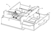
- FIG. 6 is a perspective view of a sheet feed system in a wide media mode according to an example embodiment
- FIG. 7 is a perspective view of the sheet feed system in a narrow media mode according to the example embodiment of FIG. 6 ;
- FIG. 8 is a perspective view of the sheet feed system in FIGS. 6 and 7 with a media tray partially removed from the imaging apparatus;
- FIG. 9 is a top plan view of FIG. 6 ;
- FIG. 10 is a top plan view of FIG. 7 ;
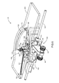
- FIG. 11 is an exploded perspective view of the sheet feed assembly of FIGS. 6 and 7 .
- FIG. 1 illustrates a perspective view of an imaging apparatus 10 .
- Imaging apparatus 10 which may be a standalone imaging device, includes a housing 12 having an input media tray 14 for supporting sheets of media, such as, but not limited to, paper, card stock film, such as transparencies, or printer labels.
- the input media tray 14 may be inserted into or removed from the imaging apparatus 10 through an opening 20 .
- Imaging apparatus 10 may also include a media output area 22 positioned along an upper part of imaging apparatus 10 in which printed media sheets are placed.
- FIG. 2 is an illustrative embodiment depicting at least some of the components of imaging apparatus 10 .
- Imaging apparatus 10 may include a controller 30 communicatively coupled to a print engine 33 and a sheet feed system 35 .
- Controller 30 may include a processor unit (not shown) and an associated memory 37 , and may be formed as one or more Application Specific Integrated Circuits (ASICs).
- Memory 37 may be any memory device convenient for use with controller 30 .
- Controller 30 may communicate with print engine 33 . Controller 30 may serve to process print data and to operate print engine 33 during printing of an image onto a sheet of media.
- Print engine 33 may include any of a variety of different types of printing mechanisms including dye-sublimation, dot-matrix, ink jet or laser printing.
- Imaging apparatus 10 may include a user interface 17 ( FIG. 1 ), such as a graphical user interface, for receiving user input concerning operations performed or to be performed by imaging apparatus 10 , and for providing to the user information concerning the same.
- the user interface 17 may include firmware maintained in memory 37 within housing 12 which may be performed by controller 30 or other processing element.
- the user interface 17 may include a display panel 18 , which may be a touch screen display in which user input may be provided by the user touching or otherwise making contact with graphic user icons in the display panel.
- the display panel may be disposed along the upper part of imaging apparatus 10 and may be sized for providing graphic images that allow for convenient communication of information between imaging apparatus 10 and the user.
- input keys 19 may be provided to receive user input.
- imaging apparatus 10 may define a media path 39 through which media sheets travel, as indicated generally by arrow 41 .
- a plurality of rollers such as rollers 43 , may be disposed within imaging apparatus 10 along media path 39 for guiding a picked media sheet from input media tray 14 through media path 39 , moving the picked media sheet to a location adjacent print engine 33 for printing an image thereon and moving the picked media sheet having the printed image to media output area 22 .
- the picked media sheet may move from the input media tray 14 to media output area 22 along a substantially L-shaped media path, a C-shaped media feedpath, a straight-through feedpath or other media feedpath configuration known in the art.
- Sheet feed system 35 may include a pick arm 49 mounting a pick roller (or pick rollers) 45 which may rest on top of a media sheet 47 of media stack 16 .
- Pick roller 45 may rotate in a direction indicated by arrow 51 to move media sheet 47 into media path 39 .
- the pick arm 49 of the sheet feed system 35 may be an auto compensating pick module (ACM) having a drive train (not shown) associated with or encased within pick arm 49 for transmitting both a rotational force and a downward force to pick roller 45 .
- the drive train may include a plurality of gears, pulleys, belts or the like for transferring rotational power from a power source to pick roller 45 .
- the power source may be in the form of a motor (not shown) controlled by controller 30 , such as a D.C. motor forming part of the sheet feed system 35 , or may be in the form of a separate motor which is coupled to sheet feed system 35 using a clutch (not shown) or the like.
- a stack of widest supported media 52 and a stack of narrowest supported media 54 may be positioned within a media tray towards a reference edge 60 thereof.
- a pick arm 59 is disposed at a fixed position across the media sheet that is offset from a centerline 53 (represented by a broken line) of the widest supported media 52 such that two pick rollers 57 always contact a topmost sheet for both the stack of widest supported media 52 and the stack of narrowest supported media 54 . While this traditional arrangement generally ensures reliable sheet picking operation for both the widest and narrowest supported media, pick reliability of the widest supported media is compromised.
- the offset arrangement of the pick arm 59 creates a moment indicated by arrow 65 onto the top media sheet of the widest supported media 52 that results in skewing the topmost sheet upon feeding into the imaging apparatus, thereby increasing the probability of paper jams.
- media pick forces should remain substantially balanced about the centerline of a media to be picked regardless of media size.
- FIG. 4 shows pick arm 49 that is movable between two positions A and B.
- Pick arm 49 may be positioned along centerline 66 of a wide media 62 which may be, for example, A4, Letter, or Legal. If narrow media 64 , such as an A5 media, is loaded into media tray 14 , pick arm 49 may translate in a direction 67 lateral to the media feed direction towards the reference edge 61 to position B along centerline 68 of the narrow media 64 .
- the pick arm 49 may return to a home position every time media tray 14 is removed from the housing 12 .
- the home position may be set to a wide media setting such that pick arm 49 substantially aligns with the centerline 66 of wide media 62 .
- the home position may be in a narrow media setting where the pick arm 49 is substantially positioned along centerline 68 of narrow media 64 .
- the home position as used herein is set to the wide media setting although such description should not be considered limiting.
- the pick arm 49 may be movable between a plurality of positions across the media feed direction as shown, for example, in FIG. 5 to accommodate a wide variety of media sizes 62 , 63 , 64 and 65 .
- Sheet feed system 35 may include a pick mechanism 100 having pick arm 49 and pick rollers 45 for picking a topmost media sheet from a stack of media in tray 14 , and a pick arm translation mechanism 105 for adjusting the position of the pick arm 49 between two positions laterally and orthogonally across the media sheet stack.
- pick arm 49 may be suitably positioned along a centerline of a stack of media sheets so as to provide little if any skewing forces on the top sheet of the stack being picked.
- Pick arm 49 is slidably mounted on a shaft 107 which is mounted within the housing 12 of the imaging apparatus 10 across the stack of media sheets.
- a bracket 109 defines a space for the pick arm 49 to move along the shaft 107 .
- a bracket member 113 mounted on the shaft 107 is connected to an end of the pick arm 49 such that a sliding motion of the bracket member 113 causes the pick arm 49 to slide along the shaft 107 therewith.
- the pick arm translation mechanism 105 may include a lever arm 115 disposed above the pick mechanism 100 and pivotably mounted on a frame 119 so as to pivot about a pivot pin 110 .
- the pick arm translation mechanism 105 may further include a lever projection 121 which extends from a surface of the lever arm 115 for initiating movement of lever arm 115 and pick arm 49 , as will be discussed in greater detail below.
- a guide member 123 extending from lever arm 115 is configured to slidably travel along a curved guide slot 125 on the frame 119 so as to define the rotational movement of lever arm 115 about pivot pin 110 .
- a lever spring 131 elastically connects the lever arm 115 to a pin 133 located on a side of the frame 119 so as to support the motion of lever arm 115 and pick arm 49 from their home position for picking wide media ( FIG. 6 ) to a second position for picking narrower media ( FIG. 7 ).
- the lever arm 115 has an elongated slot 137 formed thereon while the bracket member 113 has a slide pin 139 that passes through the elongated slot 137 for operatively coupling the pick arm 49 to the lever arm 115 such that the slide pin 139 travels along the elongated slot 137 during pivoting of the lever arm 115 about the pivot pin 110 .
- the motion of slide pin 139 of lever arm 115 through elongated slot 137 facilitates linear movement of pick arm 49 along shaft 107 .
- sheet feed system 35 may also include a latch mechanism 108 for latching lever arm 115 and pick arm 49 in the home position for handling wide media.
- Latch mechanism 108 may include or be operably associated with a lock pin 127 extending upwardly from lever arm 115 through a guide slot 129 defined on frame 119 .
- Latch mechanism 108 may also include a substantially V-shaped member 144 having a first arm or prong 147 and a second arm or prong 148 so as to form a gap 145 that is sized to receive the lock pin 127 when lever arm 115 and pick arm 49 are in the home position ( FIG. 6 ).
- a lock spring 150 may be coupled to member 144 to provide a biasing force for resisting movement of the lock pin 127 from its position within member 144 corresponding to the home position. The operation of latch mechanism 108 is discussed in greater detail herein below.
- FIG. 8 is a perspective view showing the sheet feed system 35 with a media tray 14 partially removed from opening 20 of imaging apparatus 10 .
- the media tray 14 may include a side restraint 170 adjustably positioned therein for biasing a media stack (not shown) towards a reference edge 175 defined by a back wall 172 of the media tray 14 so as to restrain movement of the media stack within tray 14 .
- Media tray 14 may further include a protrusion 177 extending from the back wall 172 opposite the side restraint 170 .
- the side restraint 170 is positioned to directly contact and engage the lever projection 121 during insertion of the media tray 14 into the opening 20 when side restraint 170 is inwardly positioned within tray 14 for supporting narrow media, so as to urge lever arm 115 and pick arm 49 from their home position (supporting wider media as shown in FIGS. 6 and 9 ) towards the second position for supporting narrower media (as shown in FIGS. 7 and 10 ).
- the protrusion 177 is disposed at a location along the back wall 172 to directly contact and engage the lever projection 121 when the media tray 14 is removed from the imaging apparatus 10 (and when lever arm 115 and pick arm 49 are in the second position) so as to urge lever arm 115 and pick arm 49 from the second position (supporting narrower media) towards the home position (supporting wider media).
- FIGS. 6 and 9 respectively illustrate perspective and top plan views of the pick arm 49 positioned in a wide media mode for receiving and picking wide media 62 .
- the media tray 14 may be loaded with a stack of wide media 62 and inserted into the imaging apparatus 10 as shown in FIG. 9 .
- the side restraint 170 is adjusted to bias the stack of wide media 62 towards the back wall 172 of the media tray 14 .
- lever arm 115 and pick arm 49 are initially in the home position for picking wide media 62 , with lock pin 127 positioned in the gap of member 144 and maintained therein by a biasing force applied by lock spring 150 .
- the stack of wide media 62 may have a width that is greater than, for example, a distance between the back wall 172 and lever projection 121 when lever arm 115 and pick arm 49 are in the home position supporting wide media 62 .
- a distance between the back wall 172 and lever projection 121 when lever arm 115 and pick arm 49 are in the home position supporting wide media 62 .
- side restraint 170 and back wall 172 being greater than the distance between back wall 172 and lever projection 121
- pick arm 49 is controlled to successively pick topmost media sheets from the stack of wide media 62 .
- pick tires 45 being substantially evenly positioned about centerline 66 of wide media 62 , media sheets are picked substantially without skew.
- lever arm 115 and pick arm 49 With lever arm 115 and pick arm 49 in the home position (as shown in FIG. 9 ), protrusion 177 of back wall 172 of tray 14 fails to contact lever projection 121 when tray 114 is later removed from imaging apparatus 10 , such as to replenish the stack of media sheets therein. As a result, lever arm 115 and pick arm 49 are maintained in the home position for picking wide media.
- the side restraint 170 When the media tray 14 is loaded with a stack of narrow media 64 , the side restraint 170 is adjusted to an inner position within tray 14 so as to contact an edge of the narrow media 64 ( FIG. 10 ). In this case, the distance between side restraint 170 and back wall 172 of tray 14 is less than the distance between back wall 172 and lever projection 121 following tray insertion. As a result, when tray 14 is inserted in imaging apparatus 10 , side restraint 170 engages with lever projection 121 .
- media tray 14 is removed from the imaging apparatus 10 so as to be loaded with a new stack of media.
- protrusion 177 in the back wall 172 contacts lever projection 121 and causes projection 121 and lever arm 115 to rotate towards the opening 20 of imaging apparatus 10 about pivot pin 110 .
- the slide pin 139 of the bracket member 113 simultaneously moves along a path defined by the shaft 107 in a direction away from the back wall 172 while sliding through the elongated slot 137 . Accordingly, the pick arm 49 is slid along the bracket 109 by the bracket member 113 along the shaft 107 from the narrow media mode ( FIGS. 7 and 10 ) to the wide media mode ( FIGS. 6 and 9 ).
- the guide member 123 of the lever arm 115 is slid along the curved guide slot 125 while the lock pin 127 extending from the lever arm 115 simultaneously travels along the guide slot 129 in the frame 119 .
- the lock pin 127 is received by member 144 of the latch mechanism 108 which itself rotates upon engagement with lock pin 127 .
- the lock spring 150 is tensioned in response to rotation of member 144 due to the engagement by the lock pin 127 .
- the lock spring 150 and member 144 are arranged in a position that provides a sufficient amount of bias on the lock pin 127 that overcomes the bias exerted by the lever spring 131 on the lever arm 115 , so as to hold the lock pin 127 and the lever arm 115 in place.
- the sheet feed system 35 may include a plurality of separator rollers 180 arranged downstream of the pick mechanism 100 for receiving a media sheet picked by the pick rollers 45 .
- a distance traveled by the pick arm 49 in one pick arm translation along the shaft 107 may be the same as a spacing distance between two adjacent separator rollers 180 .
- the distance traveled by the pick arm 49 may be substantially equal to a spacing between the pick rollers 45 .
- the configuration enables alignment of the pick rollers 45 and the separator rollers 180 at each distinct position of the pick arm 49 along the shaft 107 and advantageously keeps forces substantially balanced about a picked media sheet.
- FIG. 11 is an exploded perspective view of the sheet feed system 35 including the shaft 107 , the pick arm 49 , the bracket member 113 , the pick arm translation mechanism 105 , the frame 119 , and the latch mechanism 108 .
- the pick arm 49 is housed at one end opposite the pick rollers 45 by the bracket member 113 .
- Both the pick arm 49 and the bracket member 113 are slidably mounted on the shaft 107 .
- the bracket member 113 is coupled to the pick arm translation mechanism 105 via the slide pin 139 that passes through the elongated slot 137 formed in the lever arm 115 .
- the bracket member 113 serves to keep forces associated with a pick arm translation operation from directly acting on the pick arm 49 .
- the pick arm translation forces are substantially grounded out through the bracket member 113 in both wide media mode and narrow media mode in order to keep the pick arm translation forces from placing a torque on the pick arm 49 during a pick operation and to keep a topmost media sheet from being skewed while being picked.
- pick arm translation operation has been shown and described as being automatically set during insertion of a media tray, it should be understood that a manual setting by a user may be utilized, such as by manually translating the pick arm along the shaft without activation by inserting and withdrawing input tray 14 .
- the pick arm translation mechanism may be actuated to cause a movement of the pick arm between more than two positions based on the set position of the side restraint within the media tray and/or other adjustment mechanism.
- the pick arm translation operations presented herein are applicable to any paper input source such as multi-purpose feeders, automatic document feeders, high capacity input options, or standard paper trays without departing from the scope of the present disclosure.
Landscapes
- Engineering & Computer Science (AREA)
- Mechanical Engineering (AREA)
- Sheets, Magazines, And Separation Thereof (AREA)
Abstract
Description
Claims (21)
Priority Applications (1)
| Application Number | Priority Date | Filing Date | Title |
|---|---|---|---|
| US13/198,946 US8322704B1 (en) | 2011-08-05 | 2011-08-05 | System and device for feeding sheets of media |
Applications Claiming Priority (1)
| Application Number | Priority Date | Filing Date | Title |
|---|---|---|---|
| US13/198,946 US8322704B1 (en) | 2011-08-05 | 2011-08-05 | System and device for feeding sheets of media |
Publications (1)
| Publication Number | Publication Date |
|---|---|
| US8322704B1 true US8322704B1 (en) | 2012-12-04 |
Family
ID=47226609
Family Applications (1)
| Application Number | Title | Priority Date | Filing Date |
|---|---|---|---|
| US13/198,946 Expired - Fee Related US8322704B1 (en) | 2011-08-05 | 2011-08-05 | System and device for feeding sheets of media |
Country Status (1)
| Country | Link |
|---|---|
| US (1) | US8322704B1 (en) |
Cited By (4)
| Publication number | Priority date | Publication date | Assignee | Title |
|---|---|---|---|---|
| US8474812B1 (en) * | 2012-04-25 | 2013-07-02 | Lexmark International, Inc. | Manually translatable pick mechanism for feeding sheets of media of different widths |
| US20140103602A1 (en) * | 2012-10-15 | 2014-04-17 | Lexmark International, Inc. | Automatically adjustable pick mechanism for feeding sheets of media of different widths |
| CN111376034A (en) * | 2018-12-28 | 2020-07-07 | 苏州意达诺精密科技有限公司 | Automatic screw locking machine |
| US20240253920A1 (en) * | 2023-01-31 | 2024-08-01 | Pfu Limited | Swing controller |
Citations (7)
| Publication number | Priority date | Publication date | Assignee | Title |
|---|---|---|---|---|
| US4098501A (en) * | 1975-11-06 | 1978-07-04 | Ricoh Company, Ltd. | Cassette type sheet feed apparatus for copying machine or the like |
| US5294104A (en) * | 1992-01-31 | 1994-03-15 | Brother Kogyo Kabushiki Kaisha | Paper feeding device having an adjustable paper feed roller for different sized sheets |
| US5975517A (en) * | 1997-07-09 | 1999-11-02 | Samsung Electronics Co., Ltd. | Paper feeding apparatus of printing device |
| US20070052153A1 (en) * | 2005-09-08 | 2007-03-08 | Lexmark International, Inc. | Pick mechanism with stack height dependent force for use in an image forming device |
| US20070158901A1 (en) * | 2006-01-12 | 2007-07-12 | Samsung Electronics Co., Ltd. | Document feeder for an image forming apparatus |
| US20100194022A1 (en) * | 2009-02-05 | 2010-08-05 | Kabushiki Kaisha Toshiba | Sheet finishing apparatus, sheet finishing method and image forming apparatus |
| US20110298174A1 (en) * | 2009-09-01 | 2011-12-08 | Kinpo Electronics, Inc. | Paper tray of printer |
-
2011
- 2011-08-05 US US13/198,946 patent/US8322704B1/en not_active Expired - Fee Related
Patent Citations (7)
| Publication number | Priority date | Publication date | Assignee | Title |
|---|---|---|---|---|
| US4098501A (en) * | 1975-11-06 | 1978-07-04 | Ricoh Company, Ltd. | Cassette type sheet feed apparatus for copying machine or the like |
| US5294104A (en) * | 1992-01-31 | 1994-03-15 | Brother Kogyo Kabushiki Kaisha | Paper feeding device having an adjustable paper feed roller for different sized sheets |
| US5975517A (en) * | 1997-07-09 | 1999-11-02 | Samsung Electronics Co., Ltd. | Paper feeding apparatus of printing device |
| US20070052153A1 (en) * | 2005-09-08 | 2007-03-08 | Lexmark International, Inc. | Pick mechanism with stack height dependent force for use in an image forming device |
| US20070158901A1 (en) * | 2006-01-12 | 2007-07-12 | Samsung Electronics Co., Ltd. | Document feeder for an image forming apparatus |
| US20100194022A1 (en) * | 2009-02-05 | 2010-08-05 | Kabushiki Kaisha Toshiba | Sheet finishing apparatus, sheet finishing method and image forming apparatus |
| US20110298174A1 (en) * | 2009-09-01 | 2011-12-08 | Kinpo Electronics, Inc. | Paper tray of printer |
Cited By (5)
| Publication number | Priority date | Publication date | Assignee | Title |
|---|---|---|---|---|
| US8474812B1 (en) * | 2012-04-25 | 2013-07-02 | Lexmark International, Inc. | Manually translatable pick mechanism for feeding sheets of media of different widths |
| US20140103602A1 (en) * | 2012-10-15 | 2014-04-17 | Lexmark International, Inc. | Automatically adjustable pick mechanism for feeding sheets of media of different widths |
| US9090418B2 (en) * | 2012-10-15 | 2015-07-28 | Lexmark International, Inc. | Automatically adjustable pick mechanism for feeding sheets of media of different widths |
| CN111376034A (en) * | 2018-12-28 | 2020-07-07 | 苏州意达诺精密科技有限公司 | Automatic screw locking machine |
| US20240253920A1 (en) * | 2023-01-31 | 2024-08-01 | Pfu Limited | Swing controller |
Similar Documents
| Publication | Publication Date | Title |
|---|---|---|
| US8083222B2 (en) | Stacking apparatus, transportation apparatus and recording apparatus | |
| JP4877125B2 (en) | Image recording device | |
| US8152169B2 (en) | Feeding device and image recording apparatus with the feeding device | |
| US8152391B2 (en) | Recording device with second conveying path configured to guide sheet to an upstream side of the recording unit | |
| US9694605B2 (en) | Liquid ejecting apparatus | |
| US8414206B2 (en) | Sheet conveying devices and duplex recording devices | |
| US7658375B2 (en) | Printer and dual trays for image receiver media sheets | |
| US8503923B2 (en) | Image recording apparatus | |
| EP1947041B1 (en) | Registration Gate for Multi Sheet Inserter Tray | |
| CN104118747B (en) | Sheet feeding device and possess the image processing system of sheet feeding device | |
| US8608308B2 (en) | Image recording device | |
| US9090418B2 (en) | Automatically adjustable pick mechanism for feeding sheets of media of different widths | |
| US8322704B1 (en) | System and device for feeding sheets of media | |
| US7083245B2 (en) | Recording apparatus | |
| US7331575B2 (en) | Printer and method for feeding sheets in a printer | |
| US9956793B2 (en) | Printing device | |
| US7021621B2 (en) | Sheet-supply device and printing device including the same | |
| US20090003906A1 (en) | Image forming apparatus | |
| JP2008179479A (en) | Sheet feeding device | |
| US8474812B1 (en) | Manually translatable pick mechanism for feeding sheets of media of different widths | |
| JP3679652B2 (en) | Automatic paper feeder and recording device | |
| US11453229B2 (en) | Recording apparatus | |
| JP3686023B2 (en) | Sheet feeding apparatus and image forming apparatus | |
| JP2005289625A (en) | Paper feeder | |
| JP3080177B2 (en) | Automatic paper feeder |
Legal Events
| Date | Code | Title | Description |
|---|---|---|---|
| AS | Assignment |
Owner name: LEXMARK INTERNATIONAL, INC., KENTUCKY Free format text: ASSIGNMENT OF ASSIGNORS INTEREST;ASSIGNORS:BLAIR, BRIAN ALLEN;MURRELL, NIKO JAY;ROWE, JASON LEE;AND OTHERS;REEL/FRAME:026707/0722 Effective date: 20110805 |
|
| ZAAA | Notice of allowance and fees due |
Free format text: ORIGINAL CODE: NOA |
|
| ZAAB | Notice of allowance mailed |
Free format text: ORIGINAL CODE: MN/=. |
|
| STCF | Information on status: patent grant |
Free format text: PATENTED CASE |
|
| REMI | Maintenance fee reminder mailed | ||
| FPAY | Fee payment |
Year of fee payment: 4 |
|
| SULP | Surcharge for late payment | ||
| AS | Assignment |
Owner name: CHINA CITIC BANK CORPORATION LIMITED, GUANGZHOU BR Free format text: PATENT SECURITY AGREEMENT;ASSIGNOR:LEXMARK INTERNATIONAL, INC.;REEL/FRAME:046989/0396 Effective date: 20180402 |
|
| AS | Assignment |
Owner name: CHINA CITIC BANK CORPORATION LIMITED, GUANGZHOU BR Free format text: CORRECTIVE ASSIGNMENT TO CORRECT THE INCORRECT U.S. PATENT NUMBER PREVIOUSLY RECORDED AT REEL: 046989 FRAME: 0396. ASSIGNOR(S) HEREBY CONFIRMS THE PATENT SECURITY AGREEMENT;ASSIGNOR:LEXMARK INTERNATIONAL, INC.;REEL/FRAME:047760/0795 Effective date: 20180402 |
|
| MAFP | Maintenance fee payment |
Free format text: PAYMENT OF MAINTENANCE FEE, 8TH YEAR, LARGE ENTITY (ORIGINAL EVENT CODE: M1552); ENTITY STATUS OF PATENT OWNER: LARGE ENTITY Year of fee payment: 8 |
|
| AS | Assignment |
Owner name: LEXMARK INTERNATIONAL, INC., KENTUCKY Free format text: RELEASE BY SECURED PARTY;ASSIGNOR:CHINA CITIC BANK CORPORATION LIMITED, GUANGZHOU BRANCH, AS COLLATERAL AGENT;REEL/FRAME:066345/0026 Effective date: 20220713 Owner name: LEXMARK INTERNATIONAL, INC., KENTUCKY Free format text: RELEASE OF SECURITY INTEREST;ASSIGNOR:CHINA CITIC BANK CORPORATION LIMITED, GUANGZHOU BRANCH, AS COLLATERAL AGENT;REEL/FRAME:066345/0026 Effective date: 20220713 |
|
| FEPP | Fee payment procedure |
Free format text: MAINTENANCE FEE REMINDER MAILED (ORIGINAL EVENT CODE: REM.); ENTITY STATUS OF PATENT OWNER: LARGE ENTITY |
|
| LAPS | Lapse for failure to pay maintenance fees |
Free format text: PATENT EXPIRED FOR FAILURE TO PAY MAINTENANCE FEES (ORIGINAL EVENT CODE: EXP.); ENTITY STATUS OF PATENT OWNER: LARGE ENTITY |
|
| STCH | Information on status: patent discontinuation |
Free format text: PATENT EXPIRED DUE TO NONPAYMENT OF MAINTENANCE FEES UNDER 37 CFR 1.362 |
|
| FP | Lapsed due to failure to pay maintenance fee |
Effective date: 20241204 |