US831792A - Trolley-wheel. - Google Patents
Trolley-wheel. Download PDFInfo
- Publication number
- US831792A US831792A US25233405A US1905252334A US831792A US 831792 A US831792 A US 831792A US 25233405 A US25233405 A US 25233405A US 1905252334 A US1905252334 A US 1905252334A US 831792 A US831792 A US 831792A
- Authority
- US
- United States
- Prior art keywords
- rim
- wheel
- ring
- locking
- sides
- Prior art date
- Legal status (The legal status is an assumption and is not a legal conclusion. Google has not performed a legal analysis and makes no representation as to the accuracy of the status listed.)
- Expired - Lifetime
Links
Images
Classifications
-
- F—MECHANICAL ENGINEERING; LIGHTING; HEATING; WEAPONS; BLASTING
- F16—ENGINEERING ELEMENTS AND UNITS; GENERAL MEASURES FOR PRODUCING AND MAINTAINING EFFECTIVE FUNCTIONING OF MACHINES OR INSTALLATIONS; THERMAL INSULATION IN GENERAL
- F16C—SHAFTS; FLEXIBLE SHAFTS; ELEMENTS OR CRANKSHAFT MECHANISMS; ROTARY BODIES OTHER THAN GEARING ELEMENTS; BEARINGS
- F16C33/00—Parts of bearings; Special methods for making bearings or parts thereof
- F16C33/02—Parts of sliding-contact bearings
- F16C33/04—Brasses; Bushes; Linings
- F16C33/06—Sliding surface mainly made of metal
- F16C33/10—Construction relative to lubrication
- F16C33/102—Construction relative to lubrication with grease as lubricant
Definitions
- PATENTED SEPT 25, 1906- v W. LIVINGSTONE. TROLILEY WHEEL.
- WVILLIAM LIVINGSTONE OF NE YORK, N. Y., ASSIGNOR OF THREE- EIGHTHS TO HIMSELF, AND FlVE-EIGHTHS TO EMPIRE STATE ENGINEERING COMPANY, OF NEW YORK, N. Y., A CORPORATION OF NEW YORK.
- the general principle of the state of the art in the construction of sheet-steel trolleywheels at the present time is the method of making the same of two cup-shaped half-shells supplemented by a central ring, forming, together with the sides, the grooved peripheral bearing for its contact with the wire.
- This method has the disadvantage that the two sides and the central ring cannot be joined closely together enough to avoid the two circular more or less open seams, which not only impair the efficiency of a perfect contact, but have a tendency to cut and abrade the wire in its lateral vibrations.
- My invention relates to improvements in trolleywheels stamped from sheet metal, preferably sheet-steel; and the object of my invention is to produce a trolley-wheel which shall be light, cheap, durable, and with the surface of the groove adapted to make perfeet contact with the wire, so that there shall be the least possible abrasion either of the wheel or wire and no friction other than that produced by one smooth surface running against another.
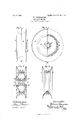
- Fig. 1 is a front view of the wheel.
- Fig. 2 is a half side view and half-section of wheel throughcenter line A B of Fig. 1.
- Fig. 3 is a transverse section of wheel through line C D of Fig. 2.
- Fig. & is a detail section of the outer rim, the locking-ring, and side-support ing ring before sides are in.
- the rim a is designed to be made in one piece, preferably from a section of soft seamless steel tubing of suitable length and diameter and having a peripheral groove of approximately semicircular form in cross-section.
- a locking-ring l) is made from a strip of soft sheet-steel of suitable length and width bent in a circular form and having a peripheral concave depression or groove therein which forms a seat for the rim a, the inner convcXly-curved periphery of which fits closely in the said groove.
- the ends of the ring are firmly pressed together, and its circumferential edges 1) Z) stand or project out perpendicular to its central plane to permit the insertion of the edges of the sides of the wheel.
- a ring 0 for supporting the sides which is made of a strip of soft steel of suitable length and width to permit its being driven tightly against the inner surface of the locking-ring I).
- the sides (Z (Z, with their hubs (Z d, which are integral therewith, are pressed and drawn from sheet-metal blanks.
- the disks (Z d, forming the sides proper, are bent inward obliquely to the axis of the hubs 7. d, so as to bring their support nearer to the center of the rim where the stress is greatest and the area and the weight of material required are the least.
- Oil-holes 0 0 through the disks near the extremity of their circumference and opposite each other are provided, as shown by Fig. 3.
- a central bushing g is made of cast brass or bronze turned outsidefand the hole is bored out and reamed. It has an oil-hole g about midway of its length, and it is provided with lubricating grooves of suitable and convenient number, length, direction,
- the diameter and concave curvature of the groovein the locking-ring b is the same as the diameter and convex curvature of the rim a.
- the rim will fit closely in the groove of the lockingring I), and when the edges 1) b, which pro ject outward and perpendicular to the central plane of the locking-ring, are turned down or flanged against the peripheral edges ii of the side pieces cl (1 all the parts so united together form a wheel in which the grooved rim will receive still greater reinforcement by the locking-ring 6, side pieces d d, and the flanged edges 1) b of the locking-ring, all pressing against the rim and increasing its solidity.
- the disk-shaped side pieces being bent obliquely inward from their center to the periphery will support the locking-ring b andthe.
- rim-a not at the extreme edges of the rim, but at such distance from the center line of its central plane that the strain and stress against the bottom of the groove will be materially resisted and the rim firmly supported.
- a sheet-metal wheel constructed of a seamless rim made in a single piece, a separate double web composed of seamless diskshaped side plates with hubs formed by central tubular projections of the respective side plates and integral therewith, and a bushing introduced into the hub and suitably secured therein, substantially as specified.
- a sheet-metal wheel constructed of a grooved seamless rim made in a single piece, a separate double web composed of seamless disk-shaped side plates with integral hubs formed by tubular projections of the respective side plates, and a bushing introduced into the hubs and secured thereto, substantially as specified.
- 3.'A sheet-metal wheel constructed of a seamless circumferentially-grooved rim made in a single piece, a double web composed of side plates, a locking-ring for fastening the rimto the side plates, the outer surface of which is circumferentially grooved to form a seat for the rim and its edges projected beyond the periphery of the side plates and turned against the same to lock them in con- Eegtion withthe rim, substantially as speci- 4.
- a sheet-metal trolley-wheel constructed of a seamless circumferentially-grooved rim made in a single piece, a double web composed of side plates having hubs integral therewith and formed by central tubular projections of the respective side plates, a ring for fastening the rim to the side plates the outer surface of which is circumferentially grooved to form a seat for the rim and its edges projected beyond the periphery of the side plates and turned against the same to hold them in connection with the rim and a bushing introduced into the hub and suitably secured thereto, substantially as specified.
- a sheet-metal wheel constructed of a seamless circumferentially-grooved rim made in a single piece, a double web composed of side plates bent inward obliquely to the axis of the wheel to bring their supporting peripheries nearer to the center of the rim, and hubs formed of central tubular projections of the respective side plates, acircumferentially-grooved locking-ring interposed between the side plates and the rim with its edges projecting beyond the sides and turned down against the same to lock them to the rim, substantially as specified.
- a trolley-wheel comprising a seamless circumferentially-grooved rim, a double web formed by sffparate disk-shaped side pieces, and a circun 'e located between the peripheries of the side pieces and the convex inner surface of the rim and having its edges turned down against the side pieces, the rim being held in the concave 'seat of the locking-ring and the side pieces secured to the locking-ring by the turned-over edgesof the latter, substantially as specified.
- a sheet-metal trolley-wheel consisting of an exterior seamless circumferentiallygrooved rim, a locking-ring, an inner siderentially-grooved locking-ring 5 supporting ring and two sides with integral stantially as specified.
- a grooved exterior rim made in a single piece, a locking-ring having a concave groove forming a seat in the inner surface of the rim, disk-shaped side pieces or webs having inward wheel the disk-shaped webs bent inward obliquely to the axis of the wheel and their peripheries placed against the locking-rihg in line with the sides of the concave groove therein and the edges of the locking-ring flanged against the peripheries to lock them in position, substantially as specified.
- a sheet-metal trolley-wheel the combination with a rim and a bushing of two seamless disk-shaped sides separate from the rim which are bent in obliquely to the axis of the wheel to bring their supporting peripheries nearer the center of the rim there being a hub formed by the inward tubular projections of the respective sides which rest upon the bushing and support the sides and the rim, substantially as specified.
Description
PATENTED SEPT. 25, 1906- v W. LIVINGSTONE. TROLILEY WHEEL.
APPLICATION FILED MAILZY, 1905.
WWW.
rm: NGRRIS PETERS cm, wAst-lmm'cu, D4 c.
UNTTED STATES PATENT OEETOE.
WVILLIAM LIVINGSTONE, OF NE YORK, N. Y., ASSIGNOR OF THREE- EIGHTHS TO HIMSELF, AND FlVE-EIGHTHS TO EMPIRE STATE ENGINEERING COMPANY, OF NEW YORK, N. Y., A CORPORATION OF NEW YORK.
Specification of Letters Patent.
TROLLEY WHEEL.
Patented Sept. 25, 1906.
To aZZ whom it nuqy concern.-
Be it known that 1, WILLIAM LIVINGSTONE, a citizen of the United States, residing at New York, Flushing, in the borough of Queens and State of New York, have invent ed a new and useful Improvement in Trolley- VVheels, Sheaves, and the Like, of which the following is a specification.
It has hitherto been the universal practice to make trolley-wheels of cast-brass because as the electric current passes from the overhead wire to the motor through the trolleywheel it is necessary that this should be done with the least possible Waste of energy, and brass was selected as the material for the wheels because it is one of the best conductors of electricity known to the art, the established fact that the friction of the soft.
copper wire against the nearly as soft surface of the wheel is destructive to the life of both being accepted as unavoidable. Experiments made with stamped sheet-steel trolley-wheels have demonstrated the fact that the comparatively small loss in the conductivity of steel against brass is fully counterbalanced by the greater durability of both the wheel and wire.
The general principle of the state of the art in the construction of sheet-steel trolleywheels at the present time is the method of making the same of two cup-shaped half-shells supplemented by a central ring, forming, together with the sides, the grooved peripheral bearing for its contact with the wire. This method, however, has the disadvantage that the two sides and the central ring cannot be joined closely together enough to avoid the two circular more or less open seams, which not only impair the efficiency of a perfect contact, but have a tendency to cut and abrade the wire in its lateral vibrations.
My invention relates to improvements in trolleywheels stamped from sheet metal, preferably sheet-steel; and the object of my invention is to produce a trolley-wheel which shall be light, cheap, durable, and with the surface of the groove adapted to make perfeet contact with the wire, so that there shall be the least possible abrasion either of the wheel or wire and no friction other than that produced by one smooth surface running against another. I attain these objects by the construction of the mechanism illustrated in the accompanying drawings, in which- Figure 1 is a front view of the wheel. Fig. 2 is a half side view and half-section of wheel throughcenter line A B of Fig. 1. Fig. 3 is a transverse section of wheel through line C D of Fig. 2. Fig. & is a detail section of the outer rim, the locking-ring, and side-support ing ring before sides are in.
Similar letters of reference denote similar parts throughout the several figures of the drawings.
In the construction of my trolley-wheel the rim a is designed to be made in one piece, preferably from a section of soft seamless steel tubing of suitable length and diameter and having a peripheral groove of approximately semicircular form in cross-section. A locking-ring l) is made from a strip of soft sheet-steel of suitable length and width bent in a circular form and having a peripheral concave depression or groove therein which forms a seat for the rim a, the inner convcXly-curved periphery of which fits closely in the said groove. The ends of the ring are firmly pressed together, and its circumferential edges 1) Z) stand or project out perpendicular to its central plane to permit the insertion of the edges of the sides of the wheel.
There is also provided a ring 0 for supporting the sides, which is made of a strip of soft steel of suitable length and width to permit its being driven tightly against the inner surface of the locking-ring I).
The sides (Z (Z, with their hubs (Z d, which are integral therewith, are pressed and drawn from sheet-metal blanks. The disks (Z d, forming the sides proper, are bent inward obliquely to the axis of the hubs 7. d, so as to bring their support nearer to the center of the rim where the stress is greatest and the area and the weight of material required are the least. Oil-holes 0 0 through the disks near the extremity of their circumference and opposite each other are provided, as shown by Fig. 3. A central bushing g is made of cast brass or bronze turned outsidefand the hole is bored out and reamed. It has an oil-hole g about midway of its length, and it is provided with lubricating grooves of suitable and convenient number, length, direction,
width, and depth in the inner surface of the hole. It also has at both ends circular and triangular projections 9 as shown by Fig. 3 in dotted lines, which are intended to be flanged over or riveted backward against the sides d d, when all the parts of the wheel are put together,for the purpose of fastening the bushing in and as an additional provision for holding the hubs d d in their places on the bushing while the peripheral edges it of the sides at d are held against the ring 0 by the turned-over flanges b b.
It will be observed that the diameter and concave curvature of the groovein the locking-ring b is the same as the diameter and convex curvature of the rim a. Hence the rim will fit closely in the groove of the lockingring I), and when the edges 1) b, which pro ject outward and perpendicular to the central plane of the locking-ring, are turned down or flanged against the peripheral edges ii of the side pieces cl (1 all the parts so united together form a wheel in which the grooved rim will receive still greater reinforcement by the locking-ring 6, side pieces d d, and the flanged edges 1) b of the locking-ring, all pressing against the rim and increasing its solidity. Moreover, the disk-shaped side pieces being bent obliquely inward from their center to the periphery will support the locking-ring b andthe. rim-a, not at the extreme edges of the rim, but at such distance from the center line of its central plane that the strain and stress against the bottom of the groove will be materially resisted and the rim firmly supported.
I claim 1. A sheet-metal wheel constructed of a seamless rim made in a single piece, a separate double web composed of seamless diskshaped side plates with hubs formed by central tubular projections of the respective side plates and integral therewith, and a bushing introduced into the hub and suitably secured therein, substantially as specified.
2. A sheet-metal wheel constructed of a grooved seamless rim made in a single piece, a separate double web composed of seamless disk-shaped side plates with integral hubs formed by tubular projections of the respective side plates, and a bushing introduced into the hubs and secured thereto, substantially as specified. I 7
3.'A sheet-metal wheel constructed of a seamless circumferentially-grooved rim made in a single piece, a double web composed of side plates, a locking-ring for fastening the rimto the side plates, the outer surface of which is circumferentially grooved to form a seat for the rim and its edges projected beyond the periphery of the side plates and turned against the same to lock them in con- Eegtion withthe rim, substantially as speci- 4. A sheet-metal trolley-wheel constructed of a seamless circumferentially-grooved rim made in a single piece, a double web composed of side plates having hubs integral therewith and formed by central tubular projections of the respective side plates, a ring for fastening the rim to the side plates the outer surface of which is circumferentially grooved to form a seat for the rim and its edges projected beyond the periphery of the side plates and turned against the same to hold them in connection with the rim and a bushing introduced into the hub and suitably secured thereto, substantially as specified.
5. A sheet-metal wheel constructed of a seamless circumferentially-grooved rim made in a single piece, a double web composed of side plates bent inward obliquely to the axis of the wheel to bring their supporting peripheries nearer to the center of the rim, and hubs formed of central tubular projections of the respective side plates, acircumferentially-grooved locking-ring interposed between the side plates and the rim with its edges projecting beyond the sides and turned down against the same to lock them to the rim, substantially as specified.
6. A trolley-wheel comprising a seamless circumferentially-grooved rim, a double web formed by sffparate disk-shaped side pieces, and a circun 'e located between the peripheries of the side pieces and the convex inner surface of the rim and having its edges turned down against the side pieces, the rim being held in the concave 'seat of the locking-ring and the side pieces secured to the locking-ring by the turned-over edgesof the latter, substantially as specified.
7. A sheet-metal trolley-wheel consisting of an exterior seamless circumferentiallygrooved rim, a locking-ring, an inner siderentially-grooved locking-ring 5 supporting ring and two sides with integral stantially as specified.
8. In a sheet-metal trolley-wheel the combination with the rim and the sides of the wheel of a single-piece locking-ring which conforms to the inner surface of the rim, substantially as specified.
9. In a sheet-metal trolley-Wheel the combination with the rim the sides and lockingring, of an inner ring in close contact with the inner surface of the locking-ring and located between the sides to hold them apart and support the same when the edges of the locking-ring are flanged over against the sides, substantially as specified.
10. In a sheet-metal trolley-wheel a grooved exterior rim made in a single piece, a locking-ring having a concave groove forming a seat in the inner surface of the rim, disk-shaped side pieces or webs having inward wheel the disk-shaped webs bent inward obliquely to the axis of the wheel and their peripheries placed against the locking-rihg in line with the sides of the concave groove therein and the edges of the locking-ring flanged against the peripheries to lock them in position, substantially as specified.
11. In a sheet-metal trolley-wheel the combination with a rim and a bushing of two seamless disk-shaped sides separate from the rim which are bent in obliquely to the axis of the wheel to bring their supporting peripheries nearer the center of the rim there being a hub formed by the inward tubular projections of the respective sides which rest upon the bushing and support the sides and the rim, substantially as specified.
In testimony that I claim the invention above set forth I have al'hxed my signature in presence of two Witnesses.
WILLIAM LIVINGSTONE.
Witnesses ARTHUR LowE, WILTON O. DONN.
Priority Applications (1)
| Application Number | Priority Date | Filing Date | Title |
|---|---|---|---|
| US25233405A US831792A (en) | 1905-03-27 | 1905-03-27 | Trolley-wheel. |
Applications Claiming Priority (1)
| Application Number | Priority Date | Filing Date | Title |
|---|---|---|---|
| US25233405A US831792A (en) | 1905-03-27 | 1905-03-27 | Trolley-wheel. |
Publications (1)
| Publication Number | Publication Date |
|---|---|
| US831792A true US831792A (en) | 1906-09-25 |
Family
ID=2900267
Family Applications (1)
| Application Number | Title | Priority Date | Filing Date |
|---|---|---|---|
| US25233405A Expired - Lifetime US831792A (en) | 1905-03-27 | 1905-03-27 | Trolley-wheel. |
Country Status (1)
| Country | Link |
|---|---|
| US (1) | US831792A (en) |
-
1905
- 1905-03-27 US US25233405A patent/US831792A/en not_active Expired - Lifetime
Similar Documents
| Publication | Publication Date | Title |
|---|---|---|
| US831792A (en) | Trolley-wheel. | |
| US1443954A (en) | Wheel | |
| US726868A (en) | Trolley-wheel. | |
| US620478A (en) | Fourths to frederick j | |
| US412155A (en) | Albert anderson | |
| US698978A (en) | Trolley-wheel. | |
| US670382A (en) | Trolley-wheel. | |
| US955863A (en) | Trolley-wheel. | |
| US781962A (en) | Trolley. | |
| US1296873A (en) | Sheet-metal wheel construction. | |
| US720612A (en) | Trolley-wheel. | |
| US703701A (en) | Trolley-wheel. | |
| US1278398A (en) | Trolley-wheel. | |
| US1039975A (en) | Trolley. | |
| US416943A (en) | Carrying-pulley | |
| US1730633A (en) | End support for rolls | |
| US726869A (en) | Trolley-wheel. | |
| US667336A (en) | Troley-head. | |
| US882450A (en) | Trolley. | |
| US612019A (en) | Vehicle-wheel | |
| US664459A (en) | Overhead electric trolley. | |
| US670712A (en) | Trolley-wheel. | |
| USRE9994E (en) | Vehicle-wheel | |
| US259924A (en) | Sand-band | |
| US790937A (en) | Trolley-wheel. |