US831756A - Lifting-jack. - Google Patents
Lifting-jack. Download PDFInfo
- Publication number
- US831756A US831756A US26482605A US1905264826A US831756A US 831756 A US831756 A US 831756A US 26482605 A US26482605 A US 26482605A US 1905264826 A US1905264826 A US 1905264826A US 831756 A US831756 A US 831756A
- Authority
- US
- United States
- Prior art keywords
- bar
- frame
- lever
- bars
- pawls
- Prior art date
- Legal status (The legal status is an assumption and is not a legal conclusion. Google has not performed a legal analysis and makes no representation as to the accuracy of the status listed.)
- Expired - Lifetime
Links
Images


Classifications
-
- B—PERFORMING OPERATIONS; TRANSPORTING
- B66—HOISTING; LIFTING; HAULING
- B66F—HOISTING, LIFTING, HAULING OR PUSHING, NOT OTHERWISE PROVIDED FOR, e.g. DEVICES WHICH APPLY A LIFTING OR PUSHING FORCE DIRECTLY TO THE SURFACE OF A LOAD
- B66F1/00—Devices, e.g. jacks, for lifting loads in predetermined steps
- B66F1/02—Devices, e.g. jacks, for lifting loads in predetermined steps with locking elements, e.g. washers, co-operating with posts
- B66F1/04—Devices, e.g. jacks, for lifting loads in predetermined steps with locking elements, e.g. washers, co-operating with posts the posts being toothed
- B66F1/06—Devices, e.g. jacks, for lifting loads in predetermined steps with locking elements, e.g. washers, co-operating with posts the posts being toothed and the devices being actuated mechanically
Landscapes
- Life Sciences & Earth Sciences (AREA)
- Engineering & Computer Science (AREA)
- Geology (AREA)
- Mechanical Engineering (AREA)
- Structural Engineering (AREA)
- Mutual Connection Of Rods And Tubes (AREA)
Description
PATENTED SEPT. 25, 1906. N. WEILER.
LIPTING JACK.
AP-PLIOATION FILED .TUNE 12. 1905.
3 SHEETS-SHEET 1.
THE NOR-RIS PETERS 654,;1! NYDN D C l a No. 831,756. PATENTED SEPT; 25, 1906. N. WEILBR.
LIFTING JACK'.
APPLIOATIM FILED JUNE 12.1905.
3 SHEETS-SHEET Z.
k\\\\\\ /N/ A PATENTED SEPT. 25
N. WEILER. LIFTING JACK.
APPLICATION IILBD JUNI: 12.1905.
3 SHEETS-SHEET 3.
w f, f .m m n A ,w rl W f w k a e W 6. N. DWH
UNITED sTATEs PATENT "oir-.Eroli Specification of Letters Patent.
PatentedSept. 25, 1906.
Application filed June 12, 1905. Serial No. 264.826.
To all whom, it may concern:
Be it known that I, NICHOLAS WEILER, a citizen of the United States, residing at Sioux City, in the county of Woodbury and State of Iowa, have invented a new and useful Improvement in Lifting-Jacks; and I do declare the following to be a full, clear, and exact description of the same, reference being had to the accompanying drawings, forming a part thereof.
My invention relates to lifting-jacks; and the object of my invention is to provide a jack which may be operated in one direction to raise the load and reversed when it is desired to lower it.
It is desi ed as an improvement upon my lifting jac patented une 27, 1905, No. 793,167.
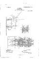
In the accompanying drawings, Figure 1 is a vertical sectional view showing the operating (parts of the jack, the springs being remove Fig. 2 is a cross-sectional view on line C D, Fig. 1. Fig. 3 is cross-sectional view on line'A B, 1. Fig. 4 is a diagrammatic view showing the operation of levers. Fig. 5 is a cross-sectional view on line E F, Fig. l. Fig. 6 is an enlarged detail view showing longitudinal section of operatinglever and the reversing mechanism. Fig. 7 is a section of outer end of operating-lever. Fig. 8 is a cross-sectional View on line X Y, Fig. 5. Fig. 9 is a detail view of joints in rod used when load is lowered.
The invention consists of a frame inclosing a hollow bar having teeth upon one side, levers pivotally connected with the frame, pawls supported by carriages in the frame and operated by springsv and levers, and a reversing mechanism operated in connection with the principal lever.
Referring now to the drawings, J is the outer frame, inclosing the hollow toothed bar G, having teeth G2.
J 2 is the base of the frame, and J J braces connecting the frame and base and supporting the frame. On each side of the front of the frame are cogged sectors J 3 J 2, projecting somewhat from the frame and formed in one piece with the frame. A lever L, forked at the end applied to raising the load, has sectors L L, with cogs L2, adapted to mesh with the cogs on the sectors J5. The forked ends of the lever L are pivotally supported by an axis L3, extending through them and also through the Hat vertical bars M M, which extend. from the axis L3 to an axis M3, and the.'V
narrow horizontal bars M M', which are pivotally supported at their inner ends by the short axes M4 M4 in the outside of theV frame. The axis M3 corresponds to the axis L3, and the outer ends of the narrow horizontal bars M2 are pivotally supported at the inner endsz by the axes M5 M5, corresponding to the axes brace J4, connecting the two sides of the` frame of the jack. The pawl-carriage O is hollow and is pivotallysup orted between the horizontal bars M near t e inner ends of said bars by short axes N N, secured to the bars and extending inwardly into annular o enings in the sides of the tpawl-carriage, ig. 8. The outer end of' t e carriage is rounded and extends. outward through the annular opening in the piece K. The pawl I?, having a large headl and narrow stem, is located inside of the carriage and is adapted to engage the teeth of the toothed bar. stem of the pawlextends outward through the rounded art of the carriage, andthe outer extremity is threaded and provided with a nut P5. A coil-spring P5 encircles the pawl and rests between the head of the pawl and the outer part of the pawl-carriage, the pressure of the springs on the carriage holding the pawl firmly against the toothed bar. A pawl-carriage O2, similar to the carriage O, is pivotally supported between the horizontal bars M2 by axes N2 N2the rounded part of the carriage extending through the other opening in the iece K. This carriage is rovided with a li e pawl P2, having the same lfind of spring and at the outer end a nut P4.
The axes M4, supporting the inner ends of the bars M', between which the u per pawlcarriage is pivoted, being situated at about the center of the carriage and in front of the axes N of the pawl-carriage, this carriage and pawl are lowered when the lever is raised. The axes M5 being situated in the rear of the lower pawl-carriage and of its axes N2, this carriage and pawl are raised when the operat- The IOO
ing-lever is raised. When a movement is imparted to the operating-lever, the awls and carriages are alternately elevate the lower ones being raised when the outer end of the lever 'is elevated, the spring holding the pawl in engagement. At the same timefthe upper pawl is lowered and forced out of en- ILO gagement with the toothed bar. At the downward stroke of' the lever the upper pawl 1s raised, carrying the bar upward, and at the same time the lower pawl is forced out of engagement., and, being free of the load, permits the bar to pass. The coil-springs normally hold both pawls against the bar, and they are only out of engagement during the alternatin r stroke of thc lever. When it is desired to ower the load, the operation is reversed. By throwing the pawls outward at each stroke of the lever the bar is lowered instead of raised. A fiat perpendicular piece R, having two slots corresponding to the two awls and a rounded projection R is adjusted to the stems of the pawls and held in place between the rounded parts of the carri ages and the nuts on the ends of the stems, the projection being about midway between the pawls. A lever R4, having a cam projection or enlarged end, is pivoted to the round ed projection of the piece R by means of 'the axis R2, and when the outer end of the lever R4 is raised the rounded part presses against the piece K above the center of the piece, pulling the lower end of the piece R outward andv forces the lower pawl out of engagement. When the lever is lowered, the movement is reversed andv the upper pawl is forced out. This lever may thus be used at will to alternatelythrow the pawls out in lowering the load. In Figs. 6, 7, and 9 is shown a means for using this lever in connection with the operating-lever L, which, being hollow, is l'engthened by the insertion of the handle L4. A button R3 is secured to the lever R4 and a cord R secured thereto, passing over a pulley R" upon the shaft L3 and over the lever L, where it is secured to a rod having jointed parts S, T, and U, the latter being secured to a hand-lever V, pivotally secured to the handle L4. The joints are provided in order that the rod may be easily taken apart when the handle is removed'. The part S is provided with slots S and S2, through which are inserted', respectively, the headed brads S3 and S4, which are driven into the handle L4. At the upper end of the part S is a button S5, and the lower end ofthe part T is provided with a slot or eye, which hooks upon the button. The part T has near the center a slot T2, through which is inserted into the handle L4 the headed bradv T. The lower end of the u per art U is formed into a hook and inserte in a ole in the upper end of the part T. The parts S and T are thus permitted to slide upon the lever and handle during the operation of the lever R4. When the handle is removed, the part T is first unhooked from the button S5 and removed from the brad T To remove as much friction as ossible from the bar G during its operation, tlie bar is provided with rojecting tongues G G upon each side, w ch slide along the pulleys Gr7 upon the axes Gfs in the upper part of the sides of the frame. At the lower end the bar is provided with a pulley Gupon an axis G4, pivotally secured in an extension G5 on tho back side of the bar. The slot in the back side of the frame, Fig. 5, extending the whole height of the frame, permits the passage oi the roller, which presses upon the sides of the frame adjacent to the slot. The bar G is hollow and on the back side is provided with slots, as G6, in which may be inserted a foot H, by means of a hook H3. The foot is also provided with a roller H upon an axis H2, pivotally secured in the frame of theI foot. The foot may be adjusted to the slot, and thus utilized when w ec s are to be raised.
Having described my invention, what I claim as new, anddesire to secure by Letters Patent, is
1. The combination with an 'upright movable bar having teeth on one side thereof, and a frame supporting said bar, of bars fulcrum ed to the frame, pawls supported by said bars and adapted for engagement with said toothed bar, springs for normally holding said pawls in engagement, and a lever fulcrumed to said bars and adapted to elevate said pawls whereby the same are alternately thrown into engagement with said toothed bar and said bar raised, substantially as described.
2. The combination with an upright movable bar having teeth on one side thereof, and a frame supplorting said bar, of bars fulcrumed to t e frame, pawl-carriages fulcrumed to said bars, pawls movable in said carriages and4 adapted for engagement with said bar, springs for normally holding said pawls in engagement, and a lever fulcrumed to said bars and adapted to alternately elevate said carriages and pawls whereby said toothed bar is raised, substantially as described.
3. The combination with an upright movable bar having teeth on one side thereof, and a Jrame forming a guide or passage way for said bar, of parallel, horizontal bars fulcrumed to said frame, pawl-carriages supported by said bars, pawls movable in said carriages, and adapted to engage the teeth of said bars, springs for normally holding said pawls in engagement, and a lever ulcrumed to said parallel bars and adapted to elevate the same whereby the pawls alternately engage the teeth of said toothed bar and said bar is raised, substantially as described.
4. The combination with an upright movable bar having teeth on one side thereof, and a rame supporting said bar, of normally horizontal bars ulcrumed near the center to the frame, a pawl-carriage fulcrumed to said bars near the inner ends thereof, a pawl movable in said carriage and adapted to engage the teeth of said toothed bar, a spring fo. normally holding said pawl in engage- IOO the teeth of said upright bar, a spring for normally holding said pawl in engagement, and a lever fulcrumed to said horizontal bars and adapted to alternately raise and lower the same, substantially 'as described.
5. The combination with an upright movable bar having teeth on thefront side thereof, a frame supporting said bar, and cogged sectors on the front side of said frame, of normally horizontal bars fulcrumed to said frame, pawls supported by said bars and adapted to engage said toothed bar, springs for normally holding said pawls in engagement, and a lever fulcrumed to said bars having cogs adapted to engage the cogs of said sectors and raise said bars whereby the pawls are alternately elevated and the upright bar raised, substantially as described.
6. The combination with an upright movable bar having teeth on the front side thereof, a frame supporting said bar, and cogged sectors on the front side of said frame, of normally horizontal bars fulcrumed near the center to the frame, a pawl fulcrumed to said bars near the inner ends thereof and adapted to engage the teeth of said upright bar, bars normally horizontal fulcrumed at the inner ends to the frame, a pawl fulcrumed to said bars near the middle thereof and adapted to engage the teeth of said upright bar, means for normally holding said pawls in engagement, and a lever having cogs adapted to engage the cogs of said sectors, fulcrumed to said horizontal bars and adapted to alternately raise and lower the same, substantially as described.
7. The combination with an upright movable bar having teeth on one side thereof, and a frame supporting said bar, of bars fulcrumed to the frame, pawl-carriages supported by said bars, pawls movable in said carriages adapted to engage said upright bar, means for normally holding said pawls in en. gagement, a lever fulcrumed to said bars and adapted to elevate the same, and a lever pivotally connected with said pawls and adapted to throw the pawls out of engagement, substantially as described.
8. The combination-.,with an upright movable bar having teeth on the front side thereof, a frame supporting said bar, and cogged sectors on the front side of said frame,of normally horizontal bars fulcrumed to said frame, pawl-carriages supported by said bars, pawls movable in said carriages and adapted to engage said upright bar, means for normally holding said pawls in engagement, an operating-lever fulcrumed to said bars having cogs adapted to engage the cogs of said sectors, a lever pivotally connected with said pawls and adapted to throw the pawls out of engagement, and means connecting said lever with the operating-lever whereby both levers may be used together for lowering the load, substantially as described.
9.- The combination with a hollow, uprightmovable bar having teeth on one side thereof, and a frame supporting said bar, of bars fulcrumed to the frame, pawls supported by said bars and adapted for engagement with said toothed bar, springs for normally holding said pawls in engagement, a lever fulcrumed to said bars and adapted to elevate said pawls whereby the same are alternately thrown into engagement with said toothed bar and said bar raised, and rollers against which said bar is adapted to slide when raised and lowered, substantially as described.
10. The combination with a hollow, upright movable bar having teeth on one side thereof and slots in one of the other sides of said bar, and a frame supporting said bar and having a slot in one side thereof, of pawls adapted for engagement with said toothed bar, means for operating said pawls and means for holding said pawls in engagement with said bar whereby the bar is raised and lowered, a foot adapted for adjustment to the slots in said bar and a roller for reducing the friction between the foot and frame, substantially as described.
In testimony whereof I have hereunto affixed my signature in the presence of two witnesses.
NICHOLAS WEILER.
Witnesses:
E. F. SIMMoNs, RALPH H. MUNRO.
Priority Applications (1)
| Application Number | Priority Date | Filing Date | Title |
|---|---|---|---|
| US26482605A US831756A (en) | 1905-06-12 | 1905-06-12 | Lifting-jack. |
Applications Claiming Priority (1)
| Application Number | Priority Date | Filing Date | Title |
|---|---|---|---|
| US26482605A US831756A (en) | 1905-06-12 | 1905-06-12 | Lifting-jack. |
Publications (1)
| Publication Number | Publication Date |
|---|---|
| US831756A true US831756A (en) | 1906-09-25 |
Family
ID=2900231
Family Applications (1)
| Application Number | Title | Priority Date | Filing Date |
|---|---|---|---|
| US26482605A Expired - Lifetime US831756A (en) | 1905-06-12 | 1905-06-12 | Lifting-jack. |
Country Status (1)
| Country | Link |
|---|---|
| US (1) | US831756A (en) |
-
1905
- 1905-06-12 US US26482605A patent/US831756A/en not_active Expired - Lifetime
Similar Documents
| Publication | Publication Date | Title |
|---|---|---|
| US831756A (en) | Lifting-jack. | |
| US636678A (en) | Lifting-jack. | |
| US450882A (en) | Book-binder s press | |
| US388067A (en) | fbanklin nelson | |
| US835048A (en) | Lifting-jack. | |
| US927407A (en) | Power-jack. | |
| US1131597A (en) | Stop mechanism for presses. | |
| US944629A (en) | Jack. | |
| US793167A (en) | Lifting-jack. | |
| US767886A (en) | Lifting-jack. | |
| US265034A (en) | Mode of operating pawls used in lifting-jacks | |
| US330489A (en) | htjssey | |
| US449515A (en) | Lifting-jack | |
| US800235A (en) | Lifting-jack. | |
| US196788A (en) | Improvement in rock-drills | |
| US684728A (en) | Lifting-jack. | |
| US1327685A (en) | Lifting-jack | |
| US706880A (en) | Lifting-jack. | |
| US541002A (en) | Combined lifting-jack and track-liner | |
| US1280998A (en) | Jack. | |
| US732523A (en) | Lifting-jack. | |
| US1481676A (en) | Auto jack | |
| US415687A (en) | Charles tindall | |
| US111739A (en) | Improvement in cotton-presses | |
| US384705A (en) | Wagon-jack |