US831715A - Wood-sawing machine. - Google Patents
Wood-sawing machine. Download PDFInfo
- Publication number
- US831715A US831715A US1906305356A US831715A US 831715 A US831715 A US 831715A US 1906305356 A US1906305356 A US 1906305356A US 831715 A US831715 A US 831715A
- Authority
- US
- United States
- Prior art keywords
- frame
- saw
- wood
- sawing machine
- machine
- Prior art date
- Legal status (The legal status is an assumption and is not a legal conclusion. Google has not performed a legal analysis and makes no representation as to the accuracy of the status listed.)
- Expired - Lifetime
Links
Images

Classifications
-
- B—PERFORMING OPERATIONS; TRANSPORTING
- B27—WORKING OR PRESERVING WOOD OR SIMILAR MATERIAL; NAILING OR STAPLING MACHINES IN GENERAL
- B27B—SAWS FOR WOOD OR SIMILAR MATERIAL; COMPONENTS OR ACCESSORIES THEREFOR
- B27B11/00—Cross-cut reciprocating saws with power drive; Appurtenances therefor
-
- Y—GENERAL TAGGING OF NEW TECHNOLOGICAL DEVELOPMENTS; GENERAL TAGGING OF CROSS-SECTIONAL TECHNOLOGIES SPANNING OVER SEVERAL SECTIONS OF THE IPC; TECHNICAL SUBJECTS COVERED BY FORMER USPC CROSS-REFERENCE ART COLLECTIONS [XRACs] AND DIGESTS
- Y10—TECHNICAL SUBJECTS COVERED BY FORMER USPC
- Y10S—TECHNICAL SUBJECTS COVERED BY FORMER USPC CROSS-REFERENCE ART COLLECTIONS [XRACs] AND DIGESTS
- Y10S83/00—Cutting
- Y10S83/928—Vehicle-mounted tool
-
- Y—GENERAL TAGGING OF NEW TECHNOLOGICAL DEVELOPMENTS; GENERAL TAGGING OF CROSS-SECTIONAL TECHNOLOGIES SPANNING OVER SEVERAL SECTIONS OF THE IPC; TECHNICAL SUBJECTS COVERED BY FORMER USPC CROSS-REFERENCE ART COLLECTIONS [XRACs] AND DIGESTS
- Y10—TECHNICAL SUBJECTS COVERED BY FORMER USPC
- Y10T—TECHNICAL SUBJECTS COVERED BY FORMER US CLASSIFICATION
- Y10T83/00—Cutting
- Y10T83/566—Interrelated tool actuating means and means to actuate work immobilizer
- Y10T83/5669—Work clamp
- Y10T83/5705—With means providing for plural steps in clamping stroke
-
- Y—GENERAL TAGGING OF NEW TECHNOLOGICAL DEVELOPMENTS; GENERAL TAGGING OF CROSS-SECTIONAL TECHNOLOGIES SPANNING OVER SEVERAL SECTIONS OF THE IPC; TECHNICAL SUBJECTS COVERED BY FORMER USPC CROSS-REFERENCE ART COLLECTIONS [XRACs] AND DIGESTS
- Y10—TECHNICAL SUBJECTS COVERED BY FORMER USPC
- Y10T—TECHNICAL SUBJECTS COVERED BY FORMER US CLASSIFICATION
- Y10T83/00—Cutting
- Y10T83/667—Tool carrier or guide affixed to work during cutting
Definitions
- This invention relates to an improved wood-sawing machine 'which may be usefully employed for felling trees, sawing logs or cord-wood, and for other purposes to which a wood-sawing machine may be employed, the objects of the invention being to simplify and improve the construction and operation of this class of machines.
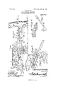
- Figure 1 is a side elevation showing the improved machine in position for felling a tree.
- Fig. 2 is a top plan view.
- Fig. 3 is a side elevation showing the machine from the opposite side to that shown in Fig. 1.
- Fig. 4 is a perspective detail view of the saw head and guide, showing the same tilted to a position at right angles to the position shown in Figs. 1, 2, and 3.
- Fig. 5 is a perspective detail view of the saw-head.
- Fig. 6 is a sectional detail view of the lubricator, which also constitutes a saw-guide.
- Fig. 7 is a perspective detail view of the latchlever for the pivoted or swinging saw-carrying frame.
- the main frame F of the improved machine is mounted for transportation upon an axle 1, having carrying-wheels 2 2.
- Said frame includes side members 3 and 4, the former of which is extended forwardly of the latter, with which it is connected by an obliquely-disposed front piece 5.
- the side members 3 4 are provided near their rear ends with brackets 6, connected by a crossbar or handle 7, whereby the machine may be manipulated when it is to be transported from place to place.
- the forward end of the side member 3 of the frame is provided with a sharp-pointed spike or barb 8.
- a grab-hook 9 having an arm 10, which is connected by means of a link-bar 11 'with a lever 12, which is pivoted upon one side of the frame near the rear end of the latter.
- Said lever is extended u 'wardly to form a handle y13, and it is provide( with a suitable spring-actuated or stop member 14, which by engaging a segment-rack 15 serves to secure the lever and the parts operated thereby at various adjustments.
- a swinging frame G Pivotally supported upon the main frame F, as by means of a king-bolt 16, is a swinging frame G, upon which are mounted brackets constituting bearings for shafts 17, 18, and 19.
- the shaft 17 carries a sprocketwheel 20, which is connected by a link belt 21 with a sprocket-wheel 22 upon the shaft 19.
- the latter which is supported near the rear end of the frame, is provided with a crank 23, capable of being operated by hand.
- the shaft 17 also carries a sprocket-wheel 24, which is connected by a link belt 25 with a sprocket-wheel 26 upon the shaft 18, which latter is thereby driven.
- the shaft 17 'finally carries a balance wheel or member consisting of a plurality of arms or spokes 27, extending radially from the shaft and carrying at their outer ends weights 28, whereby regularity of movement will be conserved.
- a guide-frame H having guides 29 for a cross-head 30, with which a saw-blade 31 is suitably connected.
- the saw-head or cross-head 30 is provided with two sockets 32 for the reception of a wristpin, as 82', said socketsbeing at right angles to eac-h other, the wrist-pin 32 in Figs. 4 and 5 being located in one of the sockets 32 and the other socket 32 being clearly shown, and
- disposed handle 39 is provided, whereby the( plivoted frame may be manipulated, said andle being shown as connected with the vI hinged frame H, so that the latter may likewise be manipulated by said handle.
- alatch-lever 40 Pivotally connected with one side of the main frame F is alatch-lever 40, having a beveled or inclined face 41, which is disposed in 2o the path of the pivoted frame.
- the opposite end of the lever carries a weight 42, serving to hold the lever normally in operative engagement with a sto member 43.
- one of the side members of said frame G will slide 3o over the inclined or beveled face of the latchlever, which latter as soon as the beveled face thereof is released from engagement with ⁇ the frame G is restored by the Weight 42 to its normal position, thus retaining the frame 3 5 G in retracted position while the machine is being placed in position for operation.
- a hollow bifurcated member 44 Suitably supported upon the frame H is a hollow bifurcated member 44, constituting a lubricant-reservoir, the same being provided 4o with a lling-plug 45.
- the inner sides or faces of the limbs of the bifurcated member 44 are provided with apertures 46, through which the lubricant may escape for the purpose of lubricating the saw-blade, which is guided between said members.
- the machine may be readily transported to the place where it is to be used-for instance, for the pur ose of felling a tree.
- the machine may e conveniently steered so as to drive the spike or barb 8 through the bark of a tree, the pivoted frame G being meanwhile held by the latchlever 40 in the retracted position. (Shown in 6o dotted lines in Fig. 2 of the drawings.)
- the grab-hook 9 is then operated to force the point or prong of said hook through the bark of the tree,
- a wood-sawing machine comprising a 9o wheeled main frame, a swinging framepivotally mounted upon said main frame, a guide-frame pivotally mounted upon Vsaid swinging frame, a saw carried by saidV guideframe, and means for operating said saw.
- a wood-sawing machine comprising a main frame having a pair of wheels upon which said main frame is movable pivotally in a vertical direction, a swinging frame pivotally mounted upon said main frame for roo movement in a horizontal direction, a movable saw, and a guide-frame pivotally mounted upon said swinging frame and ada ted to move the saw from horizontal to vertical position and vice versa.
- a wood-sawing machine comprising a pair of carrying-Wheels, a main frame pivotally mounted upon said carrying-wheels for movement in a vertical direction, a swinging frame pivotally mounted upon said main 11o frame for movement in a horizontal direction, means for moving said swinging frame relatively to said main frame, a guide-frame. pivotally mounted upon-said swinging frame, a reciprocatory saw carried by said guideirame and adapted to be moved thereby from vertical to horizontal position, and means for reciprocating said saw when in either vertical or horizontal position.
- a supporting-frame mounted tiltingly upon an axle, carrying-wheels for said axle, a frame mounted pivotally upon the supporting-frame, a guide-frame hingedly connected with the pivoted frame, a saw-carrying cross-head 12 5 mounted for reciprocation in the guide- 831,715 l' :as
- operating mechanism supported upon the pivoted frame said operating mechanism including a driven shaft having a disk, and a pitinan connecting said disk with a Wrist-pin upon the crosshead.
Description
No. 831,715. PATENTED SEPT. 25, 1906. D. E. FRANKS.
WOOD SAWING MACHINE.
APPLICATION FILED MAEJO, 1906.
2 SHEETS-SHEET 1.
WJTNESSES:
INVENTOR.
TH: NaRRls PETERS ca., usumzzran; n. c.
PA'IEN'I'ED SEPT. 25, 1906.
D. E. PRANKS.
WOOD SAWING MACHINE.
APPLICATION FILED MAR.10,1906.
2 SHEETS-SHEET 2.
A TToR/ VExS TINITEE STATES PATENT OFFTOE.
DANIEL E. FRANKS, OF CRYSTAL RIVER, FLORIDA, ASSIGNOR OF ONE- HALF TO GEORGE XV. CROSBY,
OF CRYSTAL RIVER, FLORIDA.
WOOD-SAWING MACHINE.
Specification of Letters Patent.
Patented Sept. 25, 1906.
Application filed March l0, 1906. Serial No. 305,356.
To @ZZ whom it may concern.-
Be it known that I, DANIEL E. FRANKs, a citizen of the United States, residing at Crystal River, in the county of Citrus and State of Florida, have invented` a new and useful l/Vood-Sawing Machine, of which the following is a specification.
This invention relates to an improved wood-sawing machine 'which may be usefully employed for felling trees, sawing logs or cord-wood, and for other purposes to which a wood-sawing machine may be employed, the objects of the invention being to simplify and improve the construction and operation of this class of machines.
vWith these and other ends in view, which will readily appear as the nature of the invention is better understood, the same consists in the improved construction and novel arrangement and combination of parts, which 'will be hereinafter fully described and particularly pointed out in the claims.
In the accompanying drawings has been illustrated a simple and preferred form of the invention, it being, however, understood that no limitation is necessarily made to the precise structural details therein exhibited, but that changes, alterations, and modifications within the scope of the invention may be resorted to when desired.
In the drawings, Figure 1 is a side elevation showing the improved machine in position for felling a tree. Fig. 2 is a top plan view. Fig. 3 is a side elevation showing the machine from the opposite side to that shown in Fig. 1. Fig. 4 is a perspective detail view of the saw head and guide, showing the same tilted to a position at right angles to the position shown in Figs. 1, 2, and 3. Fig. 5 is a perspective detail view of the saw-head. Fig. 6 is a sectional detail view of the lubricator, which also constitutes a saw-guide. Fig. 7 is a perspective detail view of the latchlever for the pivoted or swinging saw-carrying frame.
Corresponding parts in the several `figures are indicated throughout by similar characters of reference.
The main frame F of the improved machine is mounted for transportation upon an axle 1, having carrying-wheels 2 2. Said frame includes side members 3 and 4, the former of which is extended forwardly of the latter, with which it is connected by an obliquely-disposed front piece 5. The side members 3 4 are provided near their rear ends with brackets 6, connected by a crossbar or handle 7, whereby the machine may be manipulated when it is to be transported from place to place. The forward end of the side member 3 of the frame is provided with a sharp-pointed spike or barb 8.
Upon the under side of the frame there is pivoted a grab-hook 9, having an arm 10, which is connected by means of a link-bar 11 'with a lever 12, which is pivoted upon one side of the frame near the rear end of the latter. Said lever is extended u 'wardly to form a handle y13, and it is provide( with a suitable spring-actuated or stop member 14, which by engaging a segment-rack 15 serves to secure the lever and the parts operated thereby at various adjustments.
Pivotally supported upon the main frame F, as by means of a king-bolt 16, is a swinging frame G, upon which are mounted brackets constituting bearings for shafts 17, 18, and 19. The shaft 17 carries a sprocketwheel 20, which is connected by a link belt 21 with a sprocket-wheel 22 upon the shaft 19. The latter, which is supported near the rear end of the frame, is provided with a crank 23, capable of being operated by hand. The shaft 17 also carries a sprocket-wheel 24, which is connected by a link belt 25 with a sprocket-wheel 26 upon the shaft 18, which latter is thereby driven. The shaft 17 'finally carries a balance wheel or member consisting of a plurality of arms or spokes 27, extending radially from the shaft and carrying at their outer ends weights 28, whereby regularity of movement will be conserved.
At the forward end of the frame G is hingedly supported a guide-frame H, having guides 29 for a cross-head 30, with which a saw-blade 31 is suitably connected. The saw-head or cross-head 30 is provided with two sockets 32 for the reception of a wristpin, as 82', said socketsbeing at right angles to eac-h other, the wrist-pin 32 in Figs. 4 and 5 being located in one of the sockets 32 and the other socket 32 being clearly shown, and
IOO
disposed handle 39 is provided, whereby the( plivoted frame may be manipulated, said andle being shown as connected with the vI hinged frame H, so that the latter may likewise be manipulated by said handle.
Pivotally connected with one side of the main frame F is alatch-lever 40, having a beveled or inclined face 41, which is disposed in 2o the path of the pivoted frame. The opposite end of the lever carries a weight 42, serving to hold the lever normally in operative engagement with a sto member 43. When the pivoted frame 25 against the tension of the spring 37 to the position indicated in dotted lines in Fig. 2 of the drawings for the purpose of placing the saw in position to begin operations, one of the side members of said frame G will slide 3o over the inclined or beveled face of the latchlever, which latter as soon as the beveled face thereof is released from engagement with `the frame G is restored by the Weight 42 to its normal position, thus retaining the frame 3 5 G in retracted position while the machine is being placed in position for operation.
Suitably supported upon the frame H is a hollow bifurcated member 44, constituting a lubricant-reservoir, the same being provided 4o with a lling-plug 45. The inner sides or faces of the limbs of the bifurcated member 44 are provided with apertures 46, through which the lubricant may escape for the purpose of lubricating the saw-blade, which is guided between said members.
From the foregoing description, taken in connection with the drawings hereto annexed, the operation and advantages of this invention will be readily understood by those A5o skilled in the art to which it appertains. By
manipulating the main or'carrying frame by means of the handle 7 the machine may be readily transported to the place where it is to be used-for instance, for the pur ose of felling a tree. The machine may e conveniently steered so as to drive the spike or barb 8 through the bark of a tree, the pivoted frame G being meanwhile held by the latchlever 40 in the retracted position. (Shown in 6o dotted lines in Fig. 2 of the drawings.) Byk manipulating the lever 12 the grab-hook 9 is then operated to force the point or prong of said hook through the bark of the tree,
is retracted thereby securing the machine in operative position, the lever 12, controlling the grab- 6`5 hook, being secured by the stop member 14 engaging the segment rack 15. By releasing the frame G from the latch-lever 40 the spring 37 will be free to exercise its tension upon said frame, which will thus swing 7o around until the saw engages the treehwhen by manipulating the handle 23 a reciprocatory movement will be imparted to the saw, whereby the tree will be speedily cut through. When it is desired to utilize the machine for cutting prostrate logs, for sawing cord-wood, or the like, the pitman 34 is disconnected from the wrist-pin 32 of the cross-head 30, and the frame His then tilted to the position shown in Fig. 4 of the drawings, after which the pitman 34 is connected with the wristpin 33 of the cross-head, thus disposing the saw to operate in an approximately vertical plane. When the machine is utilized in this manner, the feed motion of the saw is obtained by gradually tilting the frame F uponV its supporting-axle.
,Havlng thus described the invention, what is claimed is- 1. A wood-sawing machine comprising a 9o wheeled main frame, a swinging framepivotally mounted upon said main frame, a guide-frame pivotally mounted upon Vsaid swinging frame, a saw carried by saidV guideframe, and means for operating said saw.
2. A wood-sawing machine comprising a main frame having a pair of wheels upon which said main frame is movable pivotally in a vertical direction, a swinging frame pivotally mounted upon said main frame for roo movement in a horizontal direction, a movable saw, and a guide-frame pivotally mounted upon said swinging frame and ada ted to move the saw from horizontal to vertical position and vice versa.
3. A wood-sawing machine comprising a pair of carrying-Wheels, a main frame pivotally mounted upon said carrying-wheels for movement in a vertical direction, a swinging frame pivotally mounted upon said main 11o frame for movement in a horizontal direction, means for moving said swinging frame relatively to said main frame, a guide-frame. pivotally mounted upon-said swinging frame, a reciprocatory saw carried by said guideirame and adapted to be moved thereby from vertical to horizontal position, and means for reciprocating said saw when in either vertical or horizontal position.
4. In a Wood-sawing machine, a supporting-frame mounted tiltingly upon an axle, carrying-wheels for said axle, a frame mounted pivotally upon the supporting-frame, a guide-frame hingedly connected with the pivoted frame, a saw-carrying cross-head 12 5 mounted for reciprocation in the guide- 831,715 l' :as
frame and having Wrist-pin-receiving sockets at right angles to each other, operating mechanism supported upon the pivoted frame said operating mechanism including a driven shaft having a disk, and a pitinan connecting said disk with a Wrist-pin upon the crosshead.
In testimony Athat I claim the foregoing as my own I have hereto aHiXed my signature 1n the presence oilA two witnesses.
DANIEL E. FRANKS,
itnessos:
R. J KNIGHT, N. BARCO.
Priority Applications (1)
| Application Number | Priority Date | Filing Date | Title |
|---|---|---|---|
| US1906305356 US831715A (en) | 1906-03-10 | 1906-03-10 | Wood-sawing machine. |
Applications Claiming Priority (1)
| Application Number | Priority Date | Filing Date | Title |
|---|---|---|---|
| US1906305356 US831715A (en) | 1906-03-10 | 1906-03-10 | Wood-sawing machine. |
Publications (1)
| Publication Number | Publication Date |
|---|---|
| US831715A true US831715A (en) | 1906-09-25 |
Family
ID=2900190
Family Applications (1)
| Application Number | Title | Priority Date | Filing Date |
|---|---|---|---|
| US1906305356 Expired - Lifetime US831715A (en) | 1906-03-10 | 1906-03-10 | Wood-sawing machine. |
Country Status (1)
| Country | Link |
|---|---|
| US (1) | US831715A (en) |
Cited By (1)
| Publication number | Priority date | Publication date | Assignee | Title |
|---|---|---|---|---|
| US7520306B1 (en) | 2004-07-01 | 2009-04-21 | Berge Albert M | Tree remover |
-
1906
- 1906-03-10 US US1906305356 patent/US831715A/en not_active Expired - Lifetime
Cited By (1)
| Publication number | Priority date | Publication date | Assignee | Title |
|---|---|---|---|---|
| US7520306B1 (en) | 2004-07-01 | 2009-04-21 | Berge Albert M | Tree remover |
Similar Documents
| Publication | Publication Date | Title |
|---|---|---|
| US831715A (en) | Wood-sawing machine. | |
| US710838A (en) | Sawing apparatus. | |
| US775247A (en) | Sawing-machine. | |
| US482103A (en) | Portable band sawing-machin e | |
| US1262955A (en) | Saw. | |
| US1246667A (en) | Portable wood-sawing machine. | |
| US360018A (en) | Drag-saw | |
| US188152A (en) | Improvement in sawing-machines | |
| US1302770A (en) | Sawing-machine. | |
| US291277A (en) | Drag-saw | |
| US386853A (en) | Log-turner | |
| US996722A (en) | Sawing-machine. | |
| US236236A (en) | John w | |
| US784184A (en) | Wood-sawing machine. | |
| US129211A (en) | Improvement in sawing-machines | |
| US250191A (en) | Sawing-machine | |
| US1419028A (en) | Portable power saw | |
| US233403A (en) | coster | |
| US402036A (en) | Tree-sawing machine | |
| US1097480A (en) | Sawing-machine. | |
| US1119524A (en) | Pneumatic portable reciprocating sawing-machine. | |
| US177619A (en) | Improvement in drag-sawing machines | |
| US1124244A (en) | Sawing-machine. | |
| US58921A (en) | Improvement in sawing-mach ines | |
| US240450A (en) | Halp to geobge m |