US8315783B2 - Engine control device for working vehicle - Google Patents
Engine control device for working vehicle Download PDFInfo
- Publication number
- US8315783B2 US8315783B2 US12/739,535 US73953508A US8315783B2 US 8315783 B2 US8315783 B2 US 8315783B2 US 73953508 A US73953508 A US 73953508A US 8315783 B2 US8315783 B2 US 8315783B2
- Authority
- US
- United States
- Prior art keywords
- speed
- engine
- detection unit
- operation amount
- stage
- Prior art date
- Legal status (The legal status is an assumption and is not a legal conclusion. Google has not performed a legal analysis and makes no representation as to the accuracy of the status listed.)
- Active, expires
Links
Images


Classifications
-
- E—FIXED CONSTRUCTIONS
- E02—HYDRAULIC ENGINEERING; FOUNDATIONS; SOIL SHIFTING
- E02F—DREDGING; SOIL-SHIFTING
- E02F9/00—Component parts of dredgers or soil-shifting machines, not restricted to one of the kinds covered by groups E02F3/00 - E02F7/00
- E02F9/20—Drives; Control devices
- E02F9/22—Hydraulic or pneumatic drives
- E02F9/2246—Control of prime movers, e.g. depending on the hydraulic load of work tools
-
- B—PERFORMING OPERATIONS; TRANSPORTING
- B60—VEHICLES IN GENERAL
- B60W—CONJOINT CONTROL OF VEHICLE SUB-UNITS OF DIFFERENT TYPE OR DIFFERENT FUNCTION; CONTROL SYSTEMS SPECIALLY ADAPTED FOR HYBRID VEHICLES; ROAD VEHICLE DRIVE CONTROL SYSTEMS FOR PURPOSES NOT RELATED TO THE CONTROL OF A PARTICULAR SUB-UNIT
- B60W10/00—Conjoint control of vehicle sub-units of different type or different function
- B60W10/04—Conjoint control of vehicle sub-units of different type or different function including control of propulsion units
- B60W10/06—Conjoint control of vehicle sub-units of different type or different function including control of propulsion units including control of combustion engines
-
- B—PERFORMING OPERATIONS; TRANSPORTING
- B60—VEHICLES IN GENERAL
- B60W—CONJOINT CONTROL OF VEHICLE SUB-UNITS OF DIFFERENT TYPE OR DIFFERENT FUNCTION; CONTROL SYSTEMS SPECIALLY ADAPTED FOR HYBRID VEHICLES; ROAD VEHICLE DRIVE CONTROL SYSTEMS FOR PURPOSES NOT RELATED TO THE CONTROL OF A PARTICULAR SUB-UNIT
- B60W10/00—Conjoint control of vehicle sub-units of different type or different function
- B60W10/30—Conjoint control of vehicle sub-units of different type or different function including control of auxiliary equipment, e.g. air-conditioning compressors or oil pumps
-
- B—PERFORMING OPERATIONS; TRANSPORTING
- B60—VEHICLES IN GENERAL
- B60W—CONJOINT CONTROL OF VEHICLE SUB-UNITS OF DIFFERENT TYPE OR DIFFERENT FUNCTION; CONTROL SYSTEMS SPECIALLY ADAPTED FOR HYBRID VEHICLES; ROAD VEHICLE DRIVE CONTROL SYSTEMS FOR PURPOSES NOT RELATED TO THE CONTROL OF A PARTICULAR SUB-UNIT
- B60W30/00—Purposes of road vehicle drive control systems not related to the control of a particular sub-unit, e.g. of systems using conjoint control of vehicle sub-units
- B60W30/18—Propelling the vehicle
- B60W30/188—Controlling power parameters of the driveline, e.g. determining the required power
- B60W30/1882—Controlling power parameters of the driveline, e.g. determining the required power characterised by the working point of the engine, e.g. by using engine output chart
-
- E—FIXED CONSTRUCTIONS
- E02—HYDRAULIC ENGINEERING; FOUNDATIONS; SOIL SHIFTING
- E02F—DREDGING; SOIL-SHIFTING
- E02F9/00—Component parts of dredgers or soil-shifting machines, not restricted to one of the kinds covered by groups E02F3/00 - E02F7/00
- E02F9/20—Drives; Control devices
- E02F9/22—Hydraulic or pneumatic drives
- E02F9/2278—Hydraulic circuits
- E02F9/2296—Systems with a variable displacement pump
-
- F—MECHANICAL ENGINEERING; LIGHTING; HEATING; WEAPONS; BLASTING
- F02—COMBUSTION ENGINES; HOT-GAS OR COMBUSTION-PRODUCT ENGINE PLANTS
- F02D—CONTROLLING COMBUSTION ENGINES
- F02D29/00—Controlling engines, such controlling being peculiar to the devices driven thereby, the devices being other than parts or accessories essential to engine operation, e.g. controlling of engines by signals external thereto
- F02D29/02—Controlling engines, such controlling being peculiar to the devices driven thereby, the devices being other than parts or accessories essential to engine operation, e.g. controlling of engines by signals external thereto peculiar to engines driving vehicles; peculiar to engines driving variable pitch propellers
-
- F—MECHANICAL ENGINEERING; LIGHTING; HEATING; WEAPONS; BLASTING
- F02—COMBUSTION ENGINES; HOT-GAS OR COMBUSTION-PRODUCT ENGINE PLANTS
- F02D—CONTROLLING COMBUSTION ENGINES
- F02D29/00—Controlling engines, such controlling being peculiar to the devices driven thereby, the devices being other than parts or accessories essential to engine operation, e.g. controlling of engines by signals external thereto
- F02D29/04—Controlling engines, such controlling being peculiar to the devices driven thereby, the devices being other than parts or accessories essential to engine operation, e.g. controlling of engines by signals external thereto peculiar to engines driving pumps
-
- F—MECHANICAL ENGINEERING; LIGHTING; HEATING; WEAPONS; BLASTING
- F02—COMBUSTION ENGINES; HOT-GAS OR COMBUSTION-PRODUCT ENGINE PLANTS
- F02D—CONTROLLING COMBUSTION ENGINES
- F02D41/00—Electrical control of supply of combustible mixture or its constituents
- F02D41/02—Circuit arrangements for generating control signals
- F02D41/021—Introducing corrections for particular conditions exterior to the engine
- F02D41/0215—Introducing corrections for particular conditions exterior to the engine in relation with elements of the transmission
- F02D41/0225—Introducing corrections for particular conditions exterior to the engine in relation with elements of the transmission in relation with the gear ratio or shift lever position
-
- B—PERFORMING OPERATIONS; TRANSPORTING
- B60—VEHICLES IN GENERAL
- B60W—CONJOINT CONTROL OF VEHICLE SUB-UNITS OF DIFFERENT TYPE OR DIFFERENT FUNCTION; CONTROL SYSTEMS SPECIALLY ADAPTED FOR HYBRID VEHICLES; ROAD VEHICLE DRIVE CONTROL SYSTEMS FOR PURPOSES NOT RELATED TO THE CONTROL OF A PARTICULAR SUB-UNIT
- B60W2510/00—Input parameters relating to a particular sub-units
- B60W2510/10—Change speed gearings
- B60W2510/1005—Transmission ratio engaged
-
- B—PERFORMING OPERATIONS; TRANSPORTING
- B60—VEHICLES IN GENERAL
- B60W—CONJOINT CONTROL OF VEHICLE SUB-UNITS OF DIFFERENT TYPE OR DIFFERENT FUNCTION; CONTROL SYSTEMS SPECIALLY ADAPTED FOR HYBRID VEHICLES; ROAD VEHICLE DRIVE CONTROL SYSTEMS FOR PURPOSES NOT RELATED TO THE CONTROL OF A PARTICULAR SUB-UNIT
- B60W2540/00—Input parameters relating to occupants
- B60W2540/10—Accelerator pedal position
- B60W2540/103—Accelerator thresholds, e.g. kickdown
-
- B—PERFORMING OPERATIONS; TRANSPORTING
- B60—VEHICLES IN GENERAL
- B60W—CONJOINT CONTROL OF VEHICLE SUB-UNITS OF DIFFERENT TYPE OR DIFFERENT FUNCTION; CONTROL SYSTEMS SPECIALLY ADAPTED FOR HYBRID VEHICLES; ROAD VEHICLE DRIVE CONTROL SYSTEMS FOR PURPOSES NOT RELATED TO THE CONTROL OF A PARTICULAR SUB-UNIT
- B60W2710/00—Output or target parameters relating to a particular sub-units
- B60W2710/06—Combustion engines, Gas turbines
- B60W2710/0644—Engine speed
-
- B—PERFORMING OPERATIONS; TRANSPORTING
- B60—VEHICLES IN GENERAL
- B60Y—INDEXING SCHEME RELATING TO ASPECTS CROSS-CUTTING VEHICLE TECHNOLOGY
- B60Y2200/00—Type of vehicle
- B60Y2200/40—Special vehicles
- B60Y2200/41—Construction vehicles, e.g. graders, excavators
- B60Y2200/415—Wheel loaders
-
- F—MECHANICAL ENGINEERING; LIGHTING; HEATING; WEAPONS; BLASTING
- F02—COMBUSTION ENGINES; HOT-GAS OR COMBUSTION-PRODUCT ENGINE PLANTS
- F02D—CONTROLLING COMBUSTION ENGINES
- F02D2200/00—Input parameters for engine control
- F02D2200/50—Input parameters for engine control said parameters being related to the vehicle or its components
- F02D2200/501—Vehicle speed
-
- F—MECHANICAL ENGINEERING; LIGHTING; HEATING; WEAPONS; BLASTING
- F02—COMBUSTION ENGINES; HOT-GAS OR COMBUSTION-PRODUCT ENGINE PLANTS
- F02D—CONTROLLING COMBUSTION ENGINES
- F02D2200/00—Input parameters for engine control
- F02D2200/60—Input parameters for engine control said parameters being related to the driver demands or status
- F02D2200/602—Pedal position
-
- F—MECHANICAL ENGINEERING; LIGHTING; HEATING; WEAPONS; BLASTING
- F02—COMBUSTION ENGINES; HOT-GAS OR COMBUSTION-PRODUCT ENGINE PLANTS
- F02D—CONTROLLING COMBUSTION ENGINES
- F02D2400/00—Control systems adapted for specific engine types; Special features of engine control systems not otherwise provided for; Power supply, connectors or cabling for engine control systems
- F02D2400/12—Engine control specially adapted for a transmission comprising a torque converter or for continuously variable transmissions
-
- F—MECHANICAL ENGINEERING; LIGHTING; HEATING; WEAPONS; BLASTING
- F02—COMBUSTION ENGINES; HOT-GAS OR COMBUSTION-PRODUCT ENGINE PLANTS
- F02D—CONTROLLING COMBUSTION ENGINES
- F02D41/00—Electrical control of supply of combustible mixture or its constituents
- F02D41/02—Circuit arrangements for generating control signals
- F02D41/14—Introducing closed-loop corrections
- F02D41/1497—With detection of the mechanical response of the engine
-
- F—MECHANICAL ENGINEERING; LIGHTING; HEATING; WEAPONS; BLASTING
- F16—ENGINEERING ELEMENTS AND UNITS; GENERAL MEASURES FOR PRODUCING AND MAINTAINING EFFECTIVE FUNCTIONING OF MACHINES OR INSTALLATIONS; THERMAL INSULATION IN GENERAL
- F16H—GEARING
- F16H59/00—Control inputs to control units of change-speed- or reversing-gearings for conveying rotary motion
- F16H59/36—Inputs being a function of speed
- F16H59/46—Inputs being a function of speed dependent on a comparison between speeds
- F16H2059/465—Detecting slip, e.g. clutch slip ratio
- F16H2059/467—Detecting slip, e.g. clutch slip ratio of torque converter
Definitions
- the present invention relates to an engine control device for a working vehicle such as a wheel loader and the like.
- Patent Reference Literature 1 There are devices known in the related art that change engine output torque characteristics in response to mode selection of a workload mode and a fuel economy saving mode (refer to, for instance, Patent Reference Literature 1). Such a device disclosed in Patent Reference Literature 1 is configured so that engine output torque in a high rotation region is set lower when the fuel economy saving mode is selected than that when the workload mode is selected and so that the maximum pump absorption torque is also set lower. As a result, great travel driving force can be obtained regardless of the mode selection.
- a greater travel driving force may result in a greater reaction force exerted upon a lift arm when a bucket is dug into a mound, thereby reducing the lifting force of the lift arm, which may reduce workability.
- An engine control device for a working vehicle that comprise: a rotation speed control unit that controls a rotation speed of an engine according to an operation amount of an accelerator pedal; a hydraulic pump driven by the engine, that supplies a driving pressure to a working actuator upon which a reaction force according to a travel driving force is exerted; and a travel drive device that transmits a rotation of the engine to wheels through a torque converter, comprises: a pedal operation amount detection unit that detects an operation amount of the accelerator pedal; a speed ratio detection unit that detects a speed ratio of an input shaft and an output shaft of the torque converter; a load pressure detection unit that detects a load pressure of the hydraulic pump; a speed stage detection unit that detects a low speed stage of a transmission capable of varying a speed stage between a low speed stage and a high speed stage; and a speed limiting unit that limits a maximum speed of the engine to a lower speed upon satisfaction of following speed limitation conditions: at least a pedal operation amount having been detected by the pedal operation amount detection unit is
- an engine control device for a working vehicle that comprises: a rotation speed control unit that controls a rotation speed of an engine according to an operation amount of an accelerator pedal; a hydraulic pump driven by the engine, that supplies driving pressure to a working actuator upon which a reaction force according to a travel driving force is exerted; and a travel drive device that transmits a rotation of the engine to wheels through a torque converter
- the engine control device for a working vehicle comprises: a pedal operation amount detection unit that detects an operation amount of the accelerator pedal; a speed ratio detection unit that detects a speed ratio of an input shaft and an output shaft of the torque converter; an operation detection unit that detects an operation of the working actuator; a speed stage detection unit that detects a low speed stage of a transmission capable of varying a speed stage between a low speed stage and a high speed stage; and a speed limiting unit that limits a maximum speed of the engine to a lower speed upon satisfaction of following speed limitation conditions: at least an operation of the working actuator is detected
- the speed stage detection unit may detect the low speed stage when a speed stage is at a second speed or lower.
- the speed limiting unit limits a maximum speed of the engine upon satisfaction of the speed limitation conditions being continued for a predetermined period of time.
- the speed limiting unit may reduce a limit value of a maximum speed of the engine over a course of time.
- travel driving force when working can be reduced and workability can be improved because it is arranged that the maximum speed of an engine is limited to lower speed when at least a pedal operation amount is equal to or greater than a predetermined value, a speed ratio of a torque converter is equal to or less than a predetermined value, a pump load pressure is equal to or greater than a predetermined value, and a speed stage of a transmission is at a low speed stage, or when at least an operation of a working actuator is detected, the pedal operation amount is equal to or greater than a predetermined value, the speed ratio of the torque converter is equal to or less than a predetermined value, and the speed stage of the transmission is at the low speed stage.
- FIG. 1 A side view of a wheel loader related to an embodiment of the present invention.
- FIG. 2 A diagram showing the general structure of an engine control device according to a first embodiment of the present invention.
- FIG. 3 An illustration showing a mode selection switch according to the first embodiment.
- FIG. 4 A diagram showing the relationships between vehicle speed and driving force at each of the speed stages.
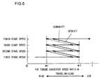
- FIG. 5 A diagram showing the timing of shift transmission by torque converter speed ratio reference control.
- FIG. 6 A diagram showing torque characteristics when an accelerator pedal is fully depressed in normal mode.
- FIG. 7 ( a ) to ( c ) Diagrams showing torque characteristics in P mode, N mode, and L mode, respectively, of the engine control device according to the present embodiment.
- FIG. 8 Diagrams showing characteristics of the maximum engine speeds of the engine control device according to the first embodiment.
- FIG. 9 A flowchart showing an example of processing executed by a controller according to the first embodiment.
- FIG. 10 Diagrams showing a speed limiting region according to the first embodiment.
- FIG. 11 An illustration showing an example of an excavation work.
- FIG. 12 A diagram showing the general structure of an engine control device according to the second embodiment of the present invention.
- FIG. 13 Diagrams showing the speed limiting region related to the second embodiment.
- FIG. 14 An illustration showing the mode selection switch according to a third embodiment.
- FIG. 15 Diagrams showing change in the maximum engine speeds by the engine control device according to the third embodiment.
- FIG. 16 A flowchart showing an example of processing executed by the controller according to the third embodiment.
- FIG. 1 is a side view of a wheel loader that is an example of a working vehicle in which the engine control device according to the present embodiment is adopted.
- a wheel loader 100 is constituted with a front body 110 that includes an arm 111 , a bucket 112 , tires 113 , and the like and a rear body 120 that includes an operator's cab 121 , an engine compartment 122 , tires 123 , and the like.
- the arm 111 vertically rotates (rises and lowers) by drive of an arm cylinder 114
- the bucket 112 vertically rotates (dumps or crowds) by drive of a bucket cylinder 115 .
- the front body 110 and the rear body 120 are rotatably connected with each other by a center pin 101 , so that the front body 110 swings side to side with respect to the rear body 120 by expansion and contraction of a steering cylinder (not shown in the figures).
- FIG. 2 is a diagram showing the general structure of the engine control device according to the first embodiment.
- An input shaft of a torque converter 2 is connected to an output shaft of an engine 1 , and an output shaft of the torque converter 2 is connected to a transmission 3 .
- the torque converter 2 is a fluid clutch constituted with a well-known impeller, a turbine, and a stator, and rotation of the engine 1 is transmitted to the transmission 3 through the torque converter 2 .
- the transmission 3 includes a hydraulic clutch that shifts the speed stage thereof, and rotation of the output shaft of the torque converter 2 is shifted by the transmission 3 . After being shifted, the rotation is transmitted to the tires 113 and 123 through a propeller shaft 4 and axles 5 , so that the vehicle travels.
- a variable displacement hydraulic pump for working 6 is driven by the engine 1 so as to discharge pressure oil. Discharged oil from the hydraulic pump 6 is led to a working actuator 8 (for instance, the arm cylinder 114 ) through a control valve 7 , so that the actuator 8 is driven.
- the control valve 7 is operated with an operation lever (not shown in the figures) so as to control the flow of pressure oil from the hydraulic pump 6 to the actuator 8 .
- the pump displacement is varied by the regulator 9 .
- the regulator 9 varies the pump displacement according to the pump discharge pressure and performs a constant torque control, for example, so that the work torque becomes constant.
- the hydraulic pump 6 may be a fixed displacement pump such as a gear pump.
- the controller 10 is constituted including an arithmetic processing unit that includes a CPU, a ROM, a RAM, other peripheral circuits, and the like. The following are connected to the controller 10 : an accelerator operation amount detector 12 that detects an operation amount s of the accelerator pedal 11 , a vehicle speed detector 13 that detects the rotation speed of an output shaft of the transmission 3 , i.e., the vehicle speed, a rotation speed detector 14 that detects a rotation speed Ni of the input shaft of the torque converter 2 , a rotation speed detector 15 that detects a rotation speed Nt of the output shaft of the torque converter 2 , a pressure detector 16 that detects a discharge pressure P of the hydraulic pump 6 , a forward/reverse changeover switch 17 for instructing advancing and reversing the vehicle, a shift switch 18 that instructs the upper limit of the speed stage between the first to the fourth speeds, and a mode selection switch 19 that selects the travel mode.
- an accelerator operation amount detector 12 that detects an operation amount s of the accelerator pedal 11
- the mode selection switch 19 is, for instance, a dial switch shown in FIG. 3 , and the P mode, the N mode, and the L mode in addition to the normal mode can be selected by operating the switch 19 .
- the normal mode is selected by an operation of a switch not shown in the figure.
- the torque converter 2 has a function to increase output torque with respect to input torque, i.e., the function to make the torque ratio 1 or greater.
- the torque ratio decreases with an increase in a torque converter speed ratio e (the output rotation speed Nt/the input rotation speed Ni), which is the ratio of the rotation speeds of the input shaft and the output shaft of the torque converter 2 .
- e the output rotation speed Nt/the input rotation speed Ni
- the output rotation speed Nt of the torque converter 2 i.e., the vehicle speed decreases and the torque converter speed ratio e is reduced.
- the vehicle can travel with a greater driving force (traction force).
- the relationships between the vehicle speed at each of the speed stages and the driving force are as shown in FIG.
- driving force is great as the vehicle speed is low (low speed, high torque) while driving force is small as the vehicle speed is high (high speed, low torque) with respect to the same speed stage.
- driving force is great as the vehicle speed is low (low speed, high torque) while driving force is small as the vehicle speed is high (high speed, low torque) with respect to the same speed stage.
- a greater driving force can be obtained at the same vehicle speed as the speed stage is lower.
- the transmission 3 is an automatic transmission that includes solenoid valves corresponding to each of the speed stages of the first speed to the fourth speed. These solenoid valves are driven by a control signal output from the controller 10 to a solenoid control unit 21 .
- torque converter speed ratio reference control in which the speed stages are shifted when the torque converter speed ratio e reaches a predetermined value
- vehicle speed reference control in which the speed stages are shifted when the vehicle speed reaches a predetermined value.
- the explanation is based on the assumption that the speed stage of the transmission 3 is controlled by torque converter speed ratio reference control.
- FIG. 5 is a diagram showing the timing of shift transmission by torque converter speed ratio reference control.
- a torque converter speed ratio e 1 that serves as a reference of upshift and a torque converter speed ratio e 2 that serves as a reference of downshift are stored in the controller 10 in advance.
- the controller 10 calculates the torque converter speed ratio e, outputs an upshift signal to the solenoid control unit 21 when the calculated speed ratio e becomes greater than the reference speed ratio e 1 , and outputs a downshift signal to the solenoid control unit 21 when the calculated speed ratio e becomes smaller than the reference speed ratio e 2 .
- the speed stage of the transmission 3 is automatically changed between the first speed and the fourth speed according to the torque converter speed ratio e. In other words, when the traveling load becomes low and the torque converter speed ratio e increases, so that the torque converter speed ratio e becomes equal to or greater than the predetermined value e 1 , the speed stage upshifts by one stage.
- the speed stage downshifts by one stage.
- the speed stage is automatically shifted, with the speed stage selected by the shift switch 18 as an upper limit.
- the speed stage is set to the first speed or the second speed when the second speed is selected by the shift switch 18 , while the speed stage is fixed to the first speed when the first speed is selected.
- the speed stage is shifted when the torque converter speed ratio e reaches the predetermined value, it may also be arranged that the speed stage is shifted when the vehicle speed reaches a predetermined value.
- an upshift signal or a downshift signal may be output to the solenoid control unit 21 according to a signal from the vehicle speed detector 13 .
- the controller 10 controls the engine speed to a target engine speed according to an operation amount of an accelerator pedal 12 . More specifically, as a depression amount of the accelerator pedal 12 becomes greater, the target engine speed becomes greater, and the controller 10 outputs a control signal corresponding to this target engine speed to an engine control unit 22 , thereby controlling the engine speed.
- FIG. 6 is a traveling performance diagram (torque diagram) showing the relationship between the engine speed and torque when the accelerator pedal 12 is fully depressed in the normal mode.
- a characteristic A 0 is an output torque (engine output torque) of the engine 1
- the difference between the characteristic A 0 and a characteristic B 0 corresponds to the maximum absorption torque (pump input torque) of the hydraulic pump 6 .
- the characteristic B 0 which is obtained by shifting the characteristic A 0 downward by pump input torque, represents the engine torque for traveling which can be used for traveling. It is to be noted that although the pump input torque varies according to the work and the torque usable for travel varies accordingly.
- the figure presents the characteristic B 0 of the travel engine torque corresponding to a typical pump input torque during excavation work.
- a characteristic C 0 in FIG. 6 is an input torque (transmission torque) of the transmission 3 when the transmission 3 is driven by the engine 1 , in which the transmission torque increases with an increase in an engine speed N.
- the characteristic C 0 is the characteristic when the torque converter speed ratio e is zero while he transmission torque decreases with an increase in the torque converter speed ratio e (refer to a characteristic C 1 of FIG. 7 ).
- a point of intersection Pb of the characteristic B 0 with the characteristic C 0 is a matching point during excavation work, and the engine speed becomes a value Nb corresponding to the matching point.
- a point of intersection Pa of the characteristic A 0 with the characteristic C 0 is a matching point when the pump input torque is zero, i.e., when the pump 6 is in an unloaded state, and the engine speed at that time is Na.
- the engine speed N varies over the range of Nb ⁇ N ⁇ Na according to the magnitude of the pump input torque. It is to be noted that the maximum speed of the engine 1 is Nc in a pump unloaded state.
- the travel driving force is proportional to the square of this engine speed N.
- the bucket 112 When the bucket 112 is dug into a mound of soil or the like during excavation work, a reaction force is exerted upon the lift arm 111 from the soil or the like. At this time, if the travel driving force is too great, the reaction force becomes great so that the lifting force of the lift arm 111 decreases, resulting in reduced workability. To prevent this, it is necessary to reduce the travel driving force by reducing the engine speed. However, it is complicated for the operator to perform so by adjusting the operation amount of the accelerator pedal 12 . In the present embodiment, therefore, upon satisfaction of a predetermined condition, the maximum speed of the engine 1 is limited lower than that in the normal mode so as to automatically lowers the matching point of the engine speed, thereby reducing the travel driving force.
- a limit value of the maximum engine speed varies depending upon travel mode. More specifically, a limitation amount increases (the maximum speed decreases) in ascending order of the P mode, the N mode, and the L mode, and the travel driving force decreases in the same ascending order.
- FIGS. 7 ( a ) to ( c ) show torque diagrams corresponding to the P mode, the N mode, and the L mode, respectively.
- the torque characteristics A 1 to A 3 are each obtained by shifting the engine output torque characteristic A 0 ( FIG. 6 ) of the high rotation area when the accelerator pedal 11 is fully depressed to the low rotation side, and correspond to the torque characteristics when the operator returns the accelerator pedal 11 .
- Characteristics B 1 to B 3 in the figures are travel engine torques corresponding to the characteristics A 1 to A 3 , respectively, and the characteristic C 1 is a transmission torque when the torque converter speed ratio e is at a predetermined value ea.
- the predetermined value ea corresponds to a torque converter speed ratio (for instance, about 0.3) that may be assumed during excavation work.
- the engine 1 upon satisfaction of a predetermined condition (engine speed limitation condition) described later, the engine 1 is controlled so that the upper limit of the engine speed becomes the following rotation speed Np, Nn, or NL according to the travel mode.
- the engine speeds at the matching points Pb and Pp are Nb and Np, respectively, and, with the pump input torque being constant, the engine speed N varies over this range (Nb ⁇ N ⁇ Np) during excavation work, so that the maximum value of the engine speed during P mode excavation becomes Np.
- the maximum speed when the pump is unloaded is Nd, which is lower than the maximum speed Nc in the normal mode.
- the matching points Pb and Pp are obtained, and the engine 1 is controlled so that the maximum speed when the pump is unloaded becomes the minimum Nd.
- the maximum value of the engine speed is limited so that the engine speed becomes equal to or less than Np during excavation work.
- the engine speed at the matching point Pn is Nn, and, with the pump input torque being constant, the maximum value of the engine speed during N mode excavation becomes Nn.
- the maximum value of the engine speed is limited so that the engine speed becomes equal to or less than Nn during excavation work.
- the engine speed at the matching point PL is NL, and, with the pump input torque being constant, the maximum value of the engine speed during L mode excavation becomes NL.
- the maximum value of the engine speed is limited so that the engine speed becomes equal to or less than NL during excavation work.
- the relationship, as shown in FIG. 8 ( a ), between the torque converter speed ratio e and the maximum values Np, Nn, and NL (a maximum engine speed Nlim) of the engine speed is stored in the controller 10 in advance.
- the maximum engine speed Nlim in the range in which the torque converter speed ratio e is equal to or less than the predetermined value ea, the maximum engine speed Nlim becomes the maximum value Np, Nn, or NL corresponding to the travel mode, and, in the range in which the torque converter speed ratio e exceeds the predetermined value ea, the maximum engine speed Nlim becomes a maximum Nmax. It is to be noted that as shown in FIG.
- the controller 10 outputs a control signal to the engine control unit 22 so as to control the maximum speed Nlim.
- FIG. 9 is a flowchart showing an example of processing executed by the controller 10 .
- the processing in this flowchart starts, for example, as an engine key switch is turned on.
- a step S 1 signals from the variety of detectors 12 to 16 and the switches 17 to 19 are read.
- a decision is made as to whether or not the accelerator pedal operation amount s, having been detected by the accelerator operation amount detector 12 , is equal to or greater than the predetermined value s 1 (s ⁇ s 1 ), i.e., whether or not the maximum speed of the engine 1 in a pump unloaded state is equal to or greater than Nd indicated in FIG. 7 ( a ). If the result of the decision is YES in the step S 2 , the flow of control proceeds to a step S 3 , while if the result of the decision is NO in the step S 2 , the flow of control proceeds to a step S 10 .
- a decision is made as to whether or not the relationship between the torque converter speed ratio which is calculated by signals from the rotation speed detectors 14 and 15 , and the pump load pressure P which is detected by the pressure detector 16 , is in a predetermined hatched region (speed limiting region) indicated in FIG. 10 ( a ).
- a decision is made as to whether or not the torque converter speed ratio e is equal to or less than the predetermined value ea and the pump load pressure P is equal to or greater than the predetermined value Pa (P ⁇ Pa), which is the load pressure assumed during excavation work.
- Pr in the figure corresponds to the relief pressure of the hydraulic pump 6 .
- a speed limiting region may also be determined so that the threshold of the pump load pressure P becomes lower relative to Pa with a reduction in the torque converter speed ratio e as shown in FIG. 10 ( b ). If the result of the decision is YES in the step. S 3 , the flow of control proceeds to a step S 4 , while if the result of the decision is NO in the step S 3 , the flow of control proceeds to the step S 10 .
- step S 4 a decision is made as to whether or not the shift switch 18 is operated to the first speed or the second speed, i.e., whether or not the speed stage of the transmission 3 is at the second speed or lower, which is a state in which an excavation work is to be performed. If the result of the decision is YES in the step S 4 , the flow of control proceeds to a step S 5 , while if the result of the decision is NO in the step S 4 , the flow of control proceeds to the step S 10 .
- step S 5 a decision is made as to whether or not the state in which the engine speed limitation condition is satisfied has continued for a predetermined period of time (for example, about 0.3 seconds). If the result of the decision is YES in the step S 5 , the flow of control proceeds to a step S 6 , while if the result of the decision is NO in the step S 5 , the flow of control proceeds to the step S 10 .
- step S 6 a decision is made as to the travel mode by a signal from the mode selection switch 19 . If the result of the decision is the P mode in the step S 6 , the flow of control proceeds to a step S 7 . If the result of the decision is the N mode, the flow of control proceeds to a step S 8 . If the result of the decision is the L mode, the flow of control proceeds to step S 9 .
- step S 7 to the step S 9 a control signal is output to the engine control unit 22 so that the maximum engine speed Nlim is set to the respective predetermined value Np, Nn, or NL. As a result, the engine output torque characteristics during excavation work are expressed as A 1 to A 3 as shown in FIGS. 7 ( a ) to ( c ), respectively.
- the engine speed is controlled to a target speed according to the operation amount of the accelerator pedal 11 .
- a travel driving force is proportional to the square of the engine speed. Therefore, for instance, a travel driving force in the L mode becomes (NL/Np) 2 times as that in the P mode. Then, the travel driving force decreases greater in the L mode than it does in the P mode, so that the reaction force exerted upon the arm 111 from the soil or the like decreases. As a result, even if the accelerator pedal 11 is fully depressed, the travel driving force does not become too great, thereby allowing the bucket 112 to be lifted with ease.
- the limitation amount of the travel driving force varies according to the travel mode, and the operator selects the travel mode according to the type of objects to be excavated such as soil. For instance, the P mode is selected in the event that the object to be excavated is hard, whilst the L mode is selected in the event that it is soft such as snow and sand.
- the bucket 112 can be operated to dig into the mound with ease with a great travel driving force in the event that the object to be excavated is hard.
- the arm 111 reaction force exerted upon is reduced so as to lift the bucket 112 with ease in the event that the object to be excavated is soft. As a result, work efficiency can be improved.
- the maximum speed of the engine 1 is limited low upon satisfaction of the engine speed limitation conditions, that is, when the accelerator pedal operation amount s is equal to or greater than the predetermined value s 1 , the torque converter speed ratio e is equal to or less than the predetermined value ea, the pump load pressure is equal to or greater than the predetermined value Pa, and the speed stage of the transmission 3 is at the second speed or lower.
- the engine speed limitation conditions that is, when the accelerator pedal operation amount s is equal to or greater than the predetermined value s 1 , the torque converter speed ratio e is equal to or less than the predetermined value ea, the pump load pressure is equal to or greater than the predetermined value Pa, and the speed stage of the transmission 3 is at the second speed or lower.
- the maximum speed can be set to a value according to the object to be excavated, resulting in appropriate performance of excavation work.
- the maximum engine speed is limited upon satisfaction of the pump load pressure P being equal to or greater than the predetermined value Pa
- the maximum engine speed is limited upon satisfaction of a lifting operation of the arm 111 .
- FIG. 12 is a diagram showing the general structure of the engine control device according to the second embodiment. It is to be noted that the same reference numerals are assigned to members identical to those in FIG. 2 .
- an operation amount detector 24 such as a stroke sensor that detects an operation amount X of an arm cylinder driving operation lever 23 is provided and a signal from the operation amount detector 24 is input to the controller 10 .
- a hydraulic sensor or the like that detects a pilot pressure exerted on the control valve 7 may be used as the operation amount detector 24 .
- a speed limiting region (hatched region) determined by the relationship between the torque converter speed ratio e and the lever operation amount X is stored in memory in advance.
- the controller 10 the same processing as that in FIG. 9 is performed.
- a decision is made as to whether or not the torque converter speed ratio e and the lever operation amount X are in the speed limiting region of FIG. 13 ( a ). More specifically, a decision is made as to whether or not the torque converter speed ratio e is equal to or less than the predetermined value ea and the lever operation amount X is equal to or greater than a predetermined value Xa (X ⁇ Xa).
- the predetermined value Xa corresponds to the lever operation amount for lifting the arm 111 after the bucket 112 is dug into the mound. It is to be noted that, in place of the threshold of the lever operation amount X being the constant value Xa, a speed limiting region may also be determined so that the threshold becomes smaller than Xa as the torque converter speed ratio e becomes smaller as shown in FIG. 13 ( b ).
- the engine speed limitation condition is satisfied when the accelerator pedal operation amount s is equal to or greater than the predetermined value s 1 (the step S 2 ), the torque converter speed ratio e is equal to or less than the predetermined value ea, the lever operation amount X is equal to or greater than the predetermined value Xa (the step S 3 ), and the speed stage of the transmission 3 is at the second speed or lower (the step S 4 ).
- the maximum speed of the engine 1 is limited low according to the travel mode (the step S 7 to the step S 9 ).
- the maximum engine speed Nlim is set according to the travel mode ( FIG. 8 )
- the maximum engine speed is changed over the course of time. It is to be noted that the following explanation will focus upon the points in which they differ from those in the first and the second embodiments.
- FIGS. 15 ( a ) and ( b ) are diagrams showing change in the maximum engine speed Nlim in the P mode and the L mode, respectively. As shown in FIG.
- the maximum engine speed Nlim is Np in the range equal to or less than a predetermined period of time T 1 (T ⁇ T 1 ), the maximum engine speed Nlim is gradually reduced from Np to NL in the range greater than the predetermined period of time T 1 and equal to or less than a predetermined period of time T 2 (T 1 ⁇ T ⁇ T 2 ), and the maximum engine speed Nlim is set to NL in the range exceeding the predetermined period of time T 2 (T 2 ⁇ T).
- the maximum engine speed Nlim is set to a constant value NL regardless of the passage of time.
- FIG. 16 is a flowchart showing an example of processing executed by the controller 10 according to the third embodiment. It is to be noted that the same reference numerals are assigned to processes identical to those in FIG. 9 .
- the characteristic of FIG. 15 ( a ) is stored in memory in the controller 10 in advance.
- the flow of control proceeds to the step S 6 so as to make a decision as to the travel mode. If the result of the decision is the P mode in the step S 6 , the flow of control proceeds to a step S 11 .
- step S 11 a control signal is output to the engine control unit 22 , so that the maximum engine speed Nlim varies according to the characteristic of FIG. 15 ( a ).
- the flow of control proceeds to the step S 9 , in which a control signal is output to the engine control unit 22 so that the maximum engine speed Nlim becomes the predetermined value NL.
- the maximum engine speed Nlim is set to Np after the engine speed limitation conditions are satisfied continuously for a predetermined period of time until the predetermined period of time T 1 has elapsed. Therefore, the travel driving force becomes great enough to allow the bucket 112 to dig into the object to be excavated. After the predetermined period of time T 1 has elapsed, the maximum engine speed Nlim gradually decreases over the course of time, and, after the predetermined period of time T 2 has elapsed, the maximum engine speed becomes NL. As a result, the travel driving force can be automatically reduced after the bucket 112 is dug into the object, and the bucket 112 can be lifted with ease.
- the travel driving force can be automatically reduced when the bucket 112 is lifted after the bucket 112 is dug into the mound, resulting in achievement of excavation work with ease. Since the maximum engine speed Nlim is gradually reduced, a shock caused by the change in the engine speed is small.
- the speed stages of the transmission 3 may be variable at least between a low speed stage and a high speed stage.
- the low speed stage corresponds to the second speed or lower of the speed stages of the transmission 3 with the four speed stages.
- any structure may be adopted in the controller 10 as a speed limiting unit as long as the maximum engine speed is limited to a lower speed at least when the pedal operation amount s is equal to or greater than the predetermined value s 1 , the torque converter speed ratio e is equal to or less than the predetermined value ea, the pump load pressure P is equal to or greater than the predetermined value Pa, and the speed stage of the transmission 3 is at the low speed stage, or at least when an operation of the working actuator 8 is detected, the pedal operation amount s is equal to or greater than the predetermined value s 1 , the torque converter speed ratio e is equal to or less than the predetermined value ea, and the speed stage of the transmission 3 is at the low speed stage.
- any structures may be adopted in the controller 10 and the engine control unit 22 as a rotation speed control unit as long as the engine speed N is controlled according to the operation amount of the accelerator pedal 11 , i.e., as long as a target engine speed is increased with an increase in the operation amount of the accelerator pedal 11 and the engine speed is controlled to the target engine speed.
- the rotation of the engine 1 is transmitted to the tires 113 and 123 through the torque converter 2 , the transmission 3 , the propeller shaft 4 , and the axles 5 , any structure may be adopted in the travel drive device.
- any structure may be adopted in the pedal operation amount detection unit.
- the torque converter speed ratio e is detected by the rotation speed detectors 14 and 15
- any structure may be adopted in the speed ratio detection unit.
- pump load pressure is detected by the pressure detector 16
- any structure may be adopted in the load pressure detection unit.
- the lever operation amount X is detected by the operation amount detector 24 so as to detect an operation of the arm cylinder 114
- any structure may be adopted in the operation detection unit.
- the speed stage of the second speed or lower is detected by the shift switch 18
- any structure may be adopted in the speed stage detection unit as long as it detects the low speed stage of the transmission 3 which is variable between the low speed stage and the high speed stage.
- the travel mode is selected with the mode selection switch 19 as a mode selection unit, the types of travel mode are not limited to those described above.
- the present invention may be adopted in the same manner in another working vehicle that includes a working machine upon which reaction force according to travel driving force is exerted. Namely, as long as the features and functions of the present invention are realized effectively, the present invention is not limited to the engine control device achieved in the embodiments.
Landscapes
- Engineering & Computer Science (AREA)
- Chemical & Material Sciences (AREA)
- Combustion & Propulsion (AREA)
- Mechanical Engineering (AREA)
- General Engineering & Computer Science (AREA)
- Transportation (AREA)
- Structural Engineering (AREA)
- Mining & Mineral Resources (AREA)
- Civil Engineering (AREA)
- Automation & Control Theory (AREA)
- Control Of Vehicle Engines Or Engines For Specific Uses (AREA)
- Operation Control Of Excavators (AREA)
- Combined Controls Of Internal Combustion Engines (AREA)
- Control Of Transmission Device (AREA)
Abstract
Description
- Patent reference literature 1: Japanese Laid Open Patent Publication No. 2005-61322
- Japanese Patent Application No. 2007-276075 (filed on 24 Oct. 2007)
Claims (10)
Applications Claiming Priority (3)
| Application Number | Priority Date | Filing Date | Title |
|---|---|---|---|
| JP2007-276075 | 2007-10-24 | ||
| JP2007276075 | 2007-10-24 | ||
| PCT/JP2008/069347 WO2009054499A1 (en) | 2007-10-24 | 2008-10-24 | Engine control device for working vehicle |
Publications (2)
| Publication Number | Publication Date |
|---|---|
| US20100262353A1 US20100262353A1 (en) | 2010-10-14 |
| US8315783B2 true US8315783B2 (en) | 2012-11-20 |
Family
ID=40579601
Family Applications (1)
| Application Number | Title | Priority Date | Filing Date |
|---|---|---|---|
| US12/739,535 Active 2029-12-07 US8315783B2 (en) | 2007-10-24 | 2008-10-24 | Engine control device for working vehicle |
Country Status (6)
| Country | Link |
|---|---|
| US (1) | US8315783B2 (en) |
| EP (1) | EP2211042B1 (en) |
| JP (1) | JP5036824B2 (en) |
| KR (1) | KR101510783B1 (en) |
| CN (1) | CN101835968B (en) |
| WO (1) | WO2009054499A1 (en) |
Cited By (4)
| Publication number | Priority date | Publication date | Assignee | Title |
|---|---|---|---|---|
| US20140379243A1 (en) * | 2012-02-03 | 2014-12-25 | Hitachi Construction Machinery Co., Ltd. | Engine Control Device for Work Vehicle |
| US9689319B2 (en) | 2014-09-12 | 2017-06-27 | Caterpillar Inc. | Power system having efficiency-based speed control |
| US9969402B2 (en) | 2015-09-28 | 2018-05-15 | Caterpillar Inc. | Transmission system having efficiency-based speed control |
| US11371213B2 (en) * | 2017-12-28 | 2022-06-28 | Hitachi Construction Machinery Co., Ltd. | Wheel loader |
Families Citing this family (32)
| Publication number | Priority date | Publication date | Assignee | Title |
|---|---|---|---|---|
| JP5156693B2 (en) * | 2009-06-17 | 2013-03-06 | 日立建機株式会社 | Industrial vehicle engine speed control device |
| EP2444636B1 (en) * | 2009-06-19 | 2018-04-11 | KCM Corporation | Motor control device for working vehicle |
| WO2010147211A1 (en) * | 2009-06-19 | 2010-12-23 | 日立建機株式会社 | Industrial vehicle control device |
| JP5164933B2 (en) * | 2009-06-19 | 2013-03-21 | 日立建機株式会社 | Control device for work vehicle |
| JP5204726B2 (en) * | 2009-06-19 | 2013-06-05 | 日立建機株式会社 | Motor vehicle control device for work vehicle |
| EP2501962B1 (en) * | 2009-11-20 | 2019-12-25 | Volvo Construction Equipment AB | A method of controlling an internal combustion engine and a control unit for controlling an internal combustion engine |
| JP5788158B2 (en) * | 2010-09-27 | 2015-09-30 | ヤンマー株式会社 | Drive system control device for work vehicle |
| CN102121425A (en) * | 2011-03-17 | 2011-07-13 | 潍柴动力股份有限公司 | Multi-power switch switching method and device |
| JP5562893B2 (en) * | 2011-03-31 | 2014-07-30 | 住友建機株式会社 | Excavator |
| JP5566333B2 (en) * | 2011-05-11 | 2014-08-06 | 日立建機株式会社 | Construction machine control system |
| CN102392747B (en) * | 2011-06-28 | 2016-09-07 | 三一汽车制造有限公司 | Control method for engine speed, control system and arm support type engineering machinery |
| FR2978212B1 (en) * | 2011-07-22 | 2018-02-16 | Manitou Bf | POWER MANAGEMENT DEVICE FOR AUTOMOTIVE HANDLING MACHINE |
| WO2013027873A1 (en) * | 2011-08-24 | 2013-02-28 | Volvo Construction Equipment Ab | Method for controlling a working machine |
| JP5586544B2 (en) * | 2011-09-08 | 2014-09-10 | 株式会社クボタ | Working machine |
| US20140257578A1 (en) * | 2011-10-24 | 2014-09-11 | Volvo Construction Equipment Ab | Controlling device used to save fuel for construction machinery |
| JP5871612B2 (en) * | 2011-12-26 | 2016-03-01 | 株式会社クボタ | Work vehicle |
| JP5996314B2 (en) * | 2012-07-24 | 2016-09-21 | 株式会社小松製作所 | Wheel loader and wheel loader engine control method |
| JP5192605B1 (en) * | 2012-09-28 | 2013-05-08 | 株式会社小松製作所 | Wheel loader |
| JP6098456B2 (en) * | 2013-09-18 | 2017-03-22 | 株式会社豊田自動織機 | Industrial vehicle |
| JP6167807B2 (en) * | 2013-09-27 | 2017-07-26 | 株式会社豊田自動織機 | Industrial vehicle |
| JP6203060B2 (en) | 2014-01-15 | 2017-09-27 | 株式会社小松製作所 | Work vehicle and control method thereof |
| JP6226758B2 (en) * | 2014-01-22 | 2017-11-08 | 住友重機械工業株式会社 | Excavators and construction machinery |
| JP6189280B2 (en) | 2014-11-28 | 2017-08-30 | 株式会社Kcm | Motor vehicle control device for work vehicle |
| KR102452805B1 (en) * | 2015-05-12 | 2022-10-11 | 현대두산인프라코어 주식회사 | Method and system for controlling wheel loader |
| CN105041491B (en) * | 2015-06-11 | 2017-08-25 | 福建纬龙机械制造有限公司 | A kind of revolution speed control system of container stacking machine |
| JP6658190B2 (en) | 2016-03-25 | 2020-03-04 | 株式会社豊田自動織機 | Vehicle speed control device |
| DE102017203835A1 (en) * | 2017-03-08 | 2018-09-13 | Zf Friedrichshafen Ag | A method for determining a target speed of a prime mover of a work machine with a continuously variable transmission and with a working hydraulics |
| US11242672B2 (en) * | 2017-09-29 | 2022-02-08 | Hitachi Construction Machinery Co., Ltd. | Wheel loader |
| CN115151699B (en) * | 2020-09-23 | 2024-10-01 | 日立建机株式会社 | Work vehicles |
| US20230055510A1 (en) * | 2021-08-18 | 2023-02-23 | Schwarze Industries, Inc. | System and method for providing a transient power assist feature in a motor vehicle |
| CN115031018B (en) * | 2022-05-09 | 2023-11-17 | 潍柴动力股份有限公司 | Method, device, processor and tractor for adjusting transmission ratio of gearbox |
| CN115324150B (en) | 2022-08-25 | 2023-09-05 | 江苏徐工工程机械研究院有限公司 | Control method of backhoe loader and backhoe loader |
Citations (8)
| Publication number | Priority date | Publication date | Assignee | Title |
|---|---|---|---|---|
| JPH0350034A (en) | 1989-07-18 | 1991-03-04 | Komatsu Ltd | How to prevent wheel loader tire slipping |
| JPH0441822A (en) | 1990-06-06 | 1992-02-12 | Komatsu Ltd | Control device and method for loading vehicle |
| JPH05295760A (en) | 1992-04-17 | 1993-11-09 | Kobe Steel Ltd | Slip preventive device of wheel type construction machine |
| JP2003184134A (en) | 2001-12-20 | 2003-07-03 | Komatsu Ltd | Control method and control device for hydraulic pump for working machine of work vehicle |
| JP2005061322A (en) | 2003-08-12 | 2005-03-10 | Hitachi Constr Mach Co Ltd | Control device of working vehicle |
| WO2006062018A1 (en) | 2004-12-10 | 2006-06-15 | Komatsu Ltd. | Construction machine |
| US20120094801A1 (en) * | 2009-06-19 | 2012-04-19 | Hitachi Construction Machinery Co., Ltd. | Motor Control Device for Working Vehicle |
| US20120100959A1 (en) * | 2009-06-19 | 2012-04-26 | Hitachi Construction Machinery Co., Ltd. | Working Vehicle Control Apparatus |
Family Cites Families (6)
| Publication number | Priority date | Publication date | Assignee | Title |
|---|---|---|---|---|
| JP2001152921A (en) * | 1999-11-19 | 2001-06-05 | Komatsu Ltd | Loading work vehicle |
| JP3819699B2 (en) * | 2000-10-20 | 2006-09-13 | 日立建機株式会社 | Hydraulic traveling vehicle |
| JP4484467B2 (en) * | 2003-08-01 | 2010-06-16 | 日立建機株式会社 | Traveling hydraulic working machine |
| JP4270505B2 (en) * | 2004-08-11 | 2009-06-03 | 株式会社小松製作所 | Load control device for engine of work vehicle |
| JP4410640B2 (en) * | 2004-09-06 | 2010-02-03 | 株式会社小松製作所 | Load control device for engine of work vehicle |
| JP4315248B2 (en) * | 2004-12-13 | 2009-08-19 | 日立建機株式会社 | Control device for traveling work vehicle |
-
2008
- 2008-10-24 CN CN2008801131370A patent/CN101835968B/en active Active
- 2008-10-24 JP JP2009538279A patent/JP5036824B2/en active Active
- 2008-10-24 EP EP08840871.1A patent/EP2211042B1/en active Active
- 2008-10-24 US US12/739,535 patent/US8315783B2/en active Active
- 2008-10-24 KR KR1020107008761A patent/KR101510783B1/en not_active Expired - Fee Related
- 2008-10-24 WO PCT/JP2008/069347 patent/WO2009054499A1/en not_active Ceased
Patent Citations (9)
| Publication number | Priority date | Publication date | Assignee | Title |
|---|---|---|---|---|
| JPH0350034A (en) | 1989-07-18 | 1991-03-04 | Komatsu Ltd | How to prevent wheel loader tire slipping |
| JPH0441822A (en) | 1990-06-06 | 1992-02-12 | Komatsu Ltd | Control device and method for loading vehicle |
| JPH05295760A (en) | 1992-04-17 | 1993-11-09 | Kobe Steel Ltd | Slip preventive device of wheel type construction machine |
| JP2003184134A (en) | 2001-12-20 | 2003-07-03 | Komatsu Ltd | Control method and control device for hydraulic pump for working machine of work vehicle |
| JP2005061322A (en) | 2003-08-12 | 2005-03-10 | Hitachi Constr Mach Co Ltd | Control device of working vehicle |
| WO2006062018A1 (en) | 2004-12-10 | 2006-06-15 | Komatsu Ltd. | Construction machine |
| US20080093145A1 (en) | 2004-12-10 | 2008-04-24 | Komatsu Ltd. | Construction Machine |
| US20120094801A1 (en) * | 2009-06-19 | 2012-04-19 | Hitachi Construction Machinery Co., Ltd. | Motor Control Device for Working Vehicle |
| US20120100959A1 (en) * | 2009-06-19 | 2012-04-26 | Hitachi Construction Machinery Co., Ltd. | Working Vehicle Control Apparatus |
Non-Patent Citations (1)
| Title |
|---|
| International Search Report dated Nov. 25, 2008, (two (2) pages). |
Cited By (5)
| Publication number | Priority date | Publication date | Assignee | Title |
|---|---|---|---|---|
| US20140379243A1 (en) * | 2012-02-03 | 2014-12-25 | Hitachi Construction Machinery Co., Ltd. | Engine Control Device for Work Vehicle |
| US9523315B2 (en) * | 2012-02-03 | 2016-12-20 | Kcm Corporation | Engine control device for work vehicle |
| US9689319B2 (en) | 2014-09-12 | 2017-06-27 | Caterpillar Inc. | Power system having efficiency-based speed control |
| US9969402B2 (en) | 2015-09-28 | 2018-05-15 | Caterpillar Inc. | Transmission system having efficiency-based speed control |
| US11371213B2 (en) * | 2017-12-28 | 2022-06-28 | Hitachi Construction Machinery Co., Ltd. | Wheel loader |
Also Published As
| Publication number | Publication date |
|---|---|
| KR101510783B1 (en) | 2015-04-10 |
| EP2211042A1 (en) | 2010-07-28 |
| JP5036824B2 (en) | 2012-09-26 |
| JPWO2009054499A1 (en) | 2011-03-10 |
| WO2009054499A1 (en) | 2009-04-30 |
| EP2211042B1 (en) | 2016-12-14 |
| US20100262353A1 (en) | 2010-10-14 |
| KR20100084636A (en) | 2010-07-27 |
| CN101835968B (en) | 2013-07-24 |
| EP2211042A4 (en) | 2013-08-14 |
| CN101835968A (en) | 2010-09-15 |
Similar Documents
| Publication | Publication Date | Title |
|---|---|---|
| US8315783B2 (en) | Engine control device for working vehicle | |
| JP5164933B2 (en) | Control device for work vehicle | |
| US20120004814A1 (en) | Engine Control Device for Work Vehicle | |
| US8423247B2 (en) | Speed change control system for industrial vehicle | |
| US8668624B2 (en) | Motor control device for working vehicle | |
| JP4975041B2 (en) | Shift control device for industrial vehicle | |
| US8655557B2 (en) | Motor control device for working vehicle | |
| US9523315B2 (en) | Engine control device for work vehicle | |
| JP4943292B2 (en) | Shift control device for work vehicle | |
| JP5061120B2 (en) | Shift control device for industrial vehicle | |
| JP4943125B2 (en) | Shift control device for industrial vehicle | |
| KR20160133322A (en) | Method and system for controlling wheel loader |
Legal Events
| Date | Code | Title | Description |
|---|---|---|---|
| AS | Assignment |
Owner name: HITACHI CONSTRUCTION MACHINERY CO., LTD., JAPAN Free format text: ASSIGNMENT OF ASSIGNORS INTEREST;ASSIGNORS:HYODO, KOJI;NAKAZONO, HIROKI;SUZUKI, NOBUHIRO;AND OTHERS;SIGNING DATES FROM 20100401 TO 20100414;REEL/FRAME:024993/0084 |
|
| STCF | Information on status: patent grant |
Free format text: PATENTED CASE |
|
| FEPP | Fee payment procedure |
Free format text: PAYOR NUMBER ASSIGNED (ORIGINAL EVENT CODE: ASPN); ENTITY STATUS OF PATENT OWNER: LARGE ENTITY |
|
| FPAY | Fee payment |
Year of fee payment: 4 |
|
| AS | Assignment |
Owner name: KCM CORPORATION, JAPAN Free format text: MERGER;ASSIGNOR:HITACHI CONSTRUCTION MACHINERY CO., LTD.;REEL/FRAME:041806/0087 Effective date: 20160422 |
|
| AS | Assignment |
Owner name: HITACHI CONSTRUCTION MACHINERY CO., LTD., JAPAN Free format text: MERGER;ASSIGNOR:KCM CORPORATION;REEL/FRAME:050088/0068 Effective date: 20190401 |
|
| MAFP | Maintenance fee payment |
Free format text: PAYMENT OF MAINTENANCE FEE, 8TH YEAR, LARGE ENTITY (ORIGINAL EVENT CODE: M1552); ENTITY STATUS OF PATENT OWNER: LARGE ENTITY Year of fee payment: 8 |
|
| MAFP | Maintenance fee payment |
Free format text: PAYMENT OF MAINTENANCE FEE, 12TH YEAR, LARGE ENTITY (ORIGINAL EVENT CODE: M1553); ENTITY STATUS OF PATENT OWNER: LARGE ENTITY Year of fee payment: 12 |