US8308942B2 - Filter system with removable enhancement media - Google Patents
Filter system with removable enhancement media Download PDFInfo
- Publication number
- US8308942B2 US8308942B2 US12/780,416 US78041610A US8308942B2 US 8308942 B2 US8308942 B2 US 8308942B2 US 78041610 A US78041610 A US 78041610A US 8308942 B2 US8308942 B2 US 8308942B2
- Authority
- US
- United States
- Prior art keywords
- water
- filter
- cartridge
- enhancement
- filter cartridge
- Prior art date
- Legal status (The legal status is an assumption and is not a legal conclusion. Google has not performed a legal analysis and makes no representation as to the accuracy of the status listed.)
- Active, expires
Links
Images


Classifications
-
- B—PERFORMING OPERATIONS; TRANSPORTING
- B01—PHYSICAL OR CHEMICAL PROCESSES OR APPARATUS IN GENERAL
- B01D—SEPARATION
- B01D35/00—Filtering devices having features not specifically covered by groups B01D24/00 - B01D33/00, or for applications not specifically covered by groups B01D24/00 - B01D33/00; Auxiliary devices for filtration; Filter housing constructions
-
- C—CHEMISTRY; METALLURGY
- C02—TREATMENT OF WATER, WASTE WATER, SEWAGE, OR SLUDGE
- C02F—TREATMENT OF WATER, WASTE WATER, SEWAGE, OR SLUDGE
- C02F1/00—Treatment of water, waste water, or sewage
- C02F1/001—Processes for the treatment of water whereby the filtration technique is of importance
- C02F1/003—Processes for the treatment of water whereby the filtration technique is of importance using household-type filters for producing potable water, e.g. pitchers, bottles, faucet mounted devices
-
- B—PERFORMING OPERATIONS; TRANSPORTING
- B01—PHYSICAL OR CHEMICAL PROCESSES OR APPARATUS IN GENERAL
- B01D—SEPARATION
- B01D27/00—Cartridge filters of the throw-away type
-
- B—PERFORMING OPERATIONS; TRANSPORTING
- B01—PHYSICAL OR CHEMICAL PROCESSES OR APPARATUS IN GENERAL
- B01D—SEPARATION
- B01D29/00—Filters with filtering elements stationary during filtration, e.g. pressure or suction filters, not covered by groups B01D24/00 - B01D27/00; Filtering elements therefor
-
- B—PERFORMING OPERATIONS; TRANSPORTING
- B01—PHYSICAL OR CHEMICAL PROCESSES OR APPARATUS IN GENERAL
- B01D—SEPARATION
- B01D35/00—Filtering devices having features not specifically covered by groups B01D24/00 - B01D33/00, or for applications not specifically covered by groups B01D24/00 - B01D33/00; Auxiliary devices for filtration; Filter housing constructions
- B01D35/02—Filters adapted for location in special places, e.g. pipe-lines, pumps, stop-cocks
-
- C—CHEMISTRY; METALLURGY
- C02—TREATMENT OF WATER, WASTE WATER, SEWAGE, OR SLUDGE
- C02F—TREATMENT OF WATER, WASTE WATER, SEWAGE, OR SLUDGE
- C02F1/00—Treatment of water, waste water, or sewage
- C02F1/28—Treatment of water, waste water, or sewage by sorption
- C02F1/283—Treatment of water, waste water, or sewage by sorption using coal, charred products, or inorganic mixtures containing them
-
- C—CHEMISTRY; METALLURGY
- C02—TREATMENT OF WATER, WASTE WATER, SEWAGE, OR SLUDGE
- C02F—TREATMENT OF WATER, WASTE WATER, SEWAGE, OR SLUDGE
- C02F2201/00—Apparatus for treatment of water, waste water or sewage
- C02F2201/002—Construction details of the apparatus
- C02F2201/004—Seals, connections
-
- C—CHEMISTRY; METALLURGY
- C02—TREATMENT OF WATER, WASTE WATER, SEWAGE, OR SLUDGE
- C02F—TREATMENT OF WATER, WASTE WATER, SEWAGE, OR SLUDGE
- C02F2201/00—Apparatus for treatment of water, waste water or sewage
- C02F2201/002—Construction details of the apparatus
- C02F2201/006—Cartridges
-
- C—CHEMISTRY; METALLURGY
- C02—TREATMENT OF WATER, WASTE WATER, SEWAGE, OR SLUDGE
- C02F—TREATMENT OF WATER, WASTE WATER, SEWAGE, OR SLUDGE
- C02F2209/00—Controlling or monitoring parameters in water treatment
- C02F2209/40—Liquid flow rate
-
- C—CHEMISTRY; METALLURGY
- C02—TREATMENT OF WATER, WASTE WATER, SEWAGE, OR SLUDGE
- C02F—TREATMENT OF WATER, WASTE WATER, SEWAGE, OR SLUDGE
- C02F2307/00—Location of water treatment or water treatment device
- C02F2307/06—Mounted on or being part of a faucet, shower handle or showerhead
Definitions
- the present invention relates generally to water treatment devices, and more particularly to countertop residential filtration units connected to existing faucets.
- Conventional residential water filter systems typically include filter units that become filled with impurities over time and therefore need to be replaced periodically. Some of these systems also include an enhancement material which includes minerals that are added to the filtered water. An important design criteria for such filter units is the efficient utilization of filter cartridges and enhancement materials.
- a filter system including a filter cartridge and an enhancement cartridge removably inserted in the filter cartridge.
- a water filter system in another embodiment, includes a base including a bottom support and a vertical support transversely extending from the bottom support.
- the bottom support includes an incoming water port for receiving unfiltered water and an outgoing water port for receiving filtered water.
- a filter cartridge is seated in the base adjacent to the vertical support and includes at least one filter element for removing impurities from the water.
- the filter cartridge includes a water inlet and a water outlet where the water inlet and the water outlet are respectively in fluid communication with the incoming water port and the outgoing water port.
- An enhancement cartridge is removably located in and in fluid communication with the filter cartridge and includes an enhancement material for adding minerals to the filtered water.
- a cover is configured to enclose the filter cartridge and the vertical support and engage the bottom support.
- a water filter system in a further embodiment, includes a base configured for receiving water from a faucet and a filter cartridge seated in the base, the filter cartridge defining a first chamber having at least one filter element, and a second chamber in fluid communication with the first chamber.
- An enhancement cartridge is removably inserted in the filter cartridge and includes a housing and a handle member removably connected to the housing, where the housing includes an enhancement material for adding minerals to the water and where the enhancement cartridge is independently removable from the filter cartridge. In situations where no minerals are to be added to the water, the enhancement cartridge is removed from the filter cartridge and the handle member is removed from the housing and re-inserted in the filter cartridge.
- FIG. 1 is a perspective view of the present water filter system attached to a faucet
- FIG. 2 is an exploded perspective view of the water filter system of FIG. 1 ;
- FIG. 3 is a front elevation view of the filter base shown in FIG. 2 ;
- FIG. 4 is a rear elevation view of the filter base of FIG. 3 ;
- FIG. 5 is a top view of the filter base of FIG. 3 ;
- FIG. 6 is a bottom view of the filter base of FIG. 3 ;
- FIG. 7 is a fragmentary perspective view of the filter cartridge shown in FIG. 2 ;
- FIG. 8 is a fragmentary perspective view of the filter cartridge including the enhancement cartridge illustrating the direction of rotation for removing the enhancement cartridge from the filter cartridge;
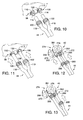
- FIG. 9 is a fragmentary perspective view of the enhancement cartridge partially removed from the filter cartridge.
- FIG. 10 is a fragmentary perspective view of the filter base showing the tubing being connected to the incoming and outgoing water ports of the filter base;
- FIG. 11 is a fragmentary perspective view of the filter base showing the tubing connected to the incoming and outgoing water ports of the filter base;
- FIG. 12 is a fragmentary perspective view of the diverter valve showing the tubing being connected to the incoming and outgoing water ports of the diverter valve;
- FIG. 13 is a fragmentary perspective view of the diverter valve showing the tubing connected to the incoming and outgoing water ports of the diverter valve.
- a filter system is used in homes and businesses to filter water used for drinking, cooking and other functions in which clean water is desired.
- the present filter system 30 includes a filter base 32 placed on a countertop or similar surface, a removable filter cartridge 34 that is sits in the filter base and includes a removable enhancement cartridge 36 , and a cover 38 that encloses the filter cartridge and engages the filter base.
- a diverter valve 40 attaches to a faucet 42 and diverts incoming water to the filter system 30 via suitable tubing 44 where the water is filtered and returned to the faucet for dispensing into a cup or other container.
- the filter base 32 includes a bottom support 46 having a generally circular cross-section and a curved vertical support 48 that transversely extends from the bottom support.
- the bottom support 46 has an upper surface 50 including opposing slots 52 for securing the cover 38 in position as described below.
- a bottom surface 54 of the bottom support 46 includes a plurality of spaced feet 56 that are preferably made with a non-slip material such as rubber. The feet 56 prevent the filter base 32 from slipping or sliding on a counter or other underlying surface.
- the vertical support 48 is curved inwardly or has a generally concave shape to correspond to an outwardly curved outer surface 58 of the filter cartridge 34 .
- the opposing side or outer surface 62 of the vertical support 48 includes a visual light display 64 , a battery housing 66 , a pair of reset buttons 68 a and 68 b , and a de-activation actuator or button 70 .
- the visual light display 64 includes a series of visual indicators, preferably lights that are generally, vertically aligned.
- the top two lights 72 and 74 are single lights. Below these lights are two groups of lights 76 and 78 where each group includes four independent, generally oval-shaped lights 80 and 82 . It is contemplated that the lights may have any suitable shape or configuration on the light display.
- the lights 72 , 74 , 80 and 82 are each light emitting diodes (LEDs) but may be any suitable type of illuminating indicator.
- each of the lights 72 , 74 , 80 and 82 illuminates or darkens independently of and sequentially relative to the other lights in the light display 64 .
- all of the lights in each of the groups of lights 76 and 78 start out being illuminated and then the topmost light in each of the groups darkens, followed by the light directly below the topmost light and so forth.
- the lights may all be one color or a combination of colors depending on the application. Preferably, the lights are provided in distinguishable colors.
- Power is provided to the lights 72 , 74 , 80 and 82 by batteries (not shown) stored in the battery housing 84 .
- electrical power can be provided to the visual light display from an electrical outlet through a cord including electrical wiring connected to a plug.
- First and second reset buttons 68 a and 68 b are respectively associated with the filter cartridge 34 and the enhancement cartridge 36 .
- Each reset button 68 a and 68 b resets the time period for replacing the filter and enhancement media cartridges 34 , 36 .
- a user presses reset button 68 a after replacing the filter cartridge 34 , and presses reset button 68 b after replacing the enhancement cartridge 36 .
- the first and second reset buttons 68 a , 68 b are spring-biased buttons as known in the art and are electrically connected by suitable wiring to the respective light groups 76 , 78 on the light display 64 .
- the de-activation button 70 is also a spring-biased button that is configured to de-activate the first group of lights 76 associated with the enhancement cartridge 36 .
- the enhancement cartridge 36 is not needed such as when the incoming water already has sufficient minerals in it. A user can therefore remove the enhancement cartridge 36 from the filter cartridge 34 as described below so that additional minerals are not added to the filtered water. Pressing the de-activation button 70 disables or de-activates the lights in the first group of lights 76 so that the lights darken or go dark to indicate that the enhancement cartridge has been removed.
- de-activation of the enhancement cartridge 36 is desirable when the water already has sufficient minerals in it or when certain users do not want one or more minerals in their water.
- the first and second reset buttons 68 a , 68 b and the de-activation button 70 may be any suitable actuators or buttons.
- the bottom support 46 defines a generally circular receptacle 84 configured to receive the filter cartridge 34 .
- the receptacle 84 is provided with a mounting ring by peripherally alternating bayonet-style tabs 86 and grooves 88 that engage corresponding tabs 90 and grooves 92 on a bottom surface 94 of the filter cartridge 34 to lock the filter cartridge to the filter base 32 in a push and twist motion as described below.
- a first opening 96 located in the center of the receptacle 84 is in fluid communication with an incoming water port 98 located on a peripheral surface 100 of the bottom support 46 .
- An O-ring 102 is inserted in the first opening 96 to form a seal between the first opening and the filter cartridge 34 .
- a second opening 104 which is adjacent to the first opening 96 , is in fluid communication with an outgoing water port 106 on the peripheral surface 100 of the bottom support 46 .
- a screen 108 is positioned in the first opening 96 to remove any particles that may remain in the incoming water.
- a screen may also be positioned in the second opening 104 to further filter out any remaining particles and other matter in the outgoing water.
- the incoming and outgoing water ports 98 , 106 each include threaded fittings 110 , 112 having barbed nozzles 114 , 116 .
- the nozzle 114 for the incoming water port 98 has a diameter that is larger than a diameter of the nozzle 116 for the outgoing water port 106 .
- By differentiating the diameters of the nozzles 114 , 116 it is easier for a user to correctly connect the respective incoming and outgoing water tubes 118 , 119 between the filter base 32 and the faucet 42 .
- Two port caps 120 , 122 FIG.
- the filter cartridge 34 includes a body 136 having a generally cylindrical shape and a cap 138 attached to the body.
- the body 136 includes a bottom wall 140 and a cylindrical wall 142 transversely extending from the bottom wall.
- inner and outer annular flanges 144 , 146 depend from the bottom wall 140 .
- the inner flange 144 defines a generally circular inlet 148 for receiving incoming water from the faucet 42 .
- a flow regulator is mounted inside the inlet to regulate the water flow into the filter cartridge. For example, a 0.9 gallon per minute (gpm) flow regulator 150 is optionally attached to the inlet to limit the flow of water through the cartridge 34 .
- gpm 0.9 gallon per minute
- the outer flange 146 defines an annular outlet 152 disposed radially outwardly from the inlet 148 . Filtered water flowing out of the filter cartridge 34 exits through the outlet 152 and then flows to the outgoing water port 106 ( FIG. 4 ).
- bayonet-style tabs 90 and grooves 92 extend laterally from the outer flange 146 and rotatably engage the corresponding tabs 86 and grooves 88 in the receptacle 84 of the filter base 32 .
- a cylindrical, support ring 154 extends upwardly from the bottom wall 140 and defines an annular flow channel 156 between the ring and the outer cylindrical wall 142 .
- a lower tray 158 is attached to and extends radially from the ring 156 .
- the lower tray 158 includes a bottom support wall 160 and radially spaced inner and outer walls 162 , 164 extending upwardly from the bottom wall where the inner wall is taller than the outer wall.
- a portion of the bottom wall 160 extending between the inner and outer walls 162 , 164 forms a bottom support 166 for a filter element 168 as described below.
- the pre-formed annular filter element 168 is seated on the bottom support 166 between the inner and outer walls 162 , 164 .
- the filter element 168 has a generally cylindrical shape and defines a central, axially-extending chamber 170 configured for receiving the enhancement cartridge 36 as described below.
- An upper tray 172 is attached to the filter element 168 and includes inner and outer radially spaced, depending walls 174 , 176 along opposing sides of the filter element.
- the filter element 168 preferably includes a radially outer filter layer 178 and an inner filter layer 180 .
- the outer filter layer 178 is made of a non-woven, nanoalumina filter which removes bacteria and viruses from the incoming water.
- One such filter is a Nanoceram® filter manufactured by Argonide Corporation.
- the inner filter layer 180 is a carbon block that removes particulates, heavy metals, organic chemicals, chlorine, and unpleasant tastes and odors from the water. It should be appreciated that any suitable filter material or combination of filter materials may be used for the outer and inner filter layers 178 , 180 . It should also be appreciated that the filter element 168 may include one or more filter layers for filtering the incoming water.
- Incoming water flows through the annular flow channel 156 and upwardly through an outer filter channel 182 defined between an outer surface 184 of the filter element 168 and the outer wall 142 .
- the filtered water enters an inner filter channel 186 defined between an inner surface 188 of the filter element 168 and the enhancement cartridge 36 .
- the filtered water travels upwardly through the inner filter channel 186 toward the top of the filter cartridge 34 .
- an annular support plate 190 is positioned on the upper tray 172 .
- the support plate 190 is a separate component that is not attached to or integrally formed with any other component in the filter cartridge 34 . As shown in FIG.
- the support plate 190 includes an upwardly extending annular wall 192 at a first end and a downwardly extending annular lip 194 near an opposing, radially outwardly spaced second end.
- the wall 192 provides support to the upper portion of the enhancement media cartridge 36 and the annular lip 194 guides the filter element 168 into position within the body 136 .
- the cap 138 has an upper side 196 defining a circular, recessed area 198 and a lower side 200 forming an inner space.
- An inner diameter of the cap 138 is generally the same as an outer diameter of the body 136 such that threads 202 on an inner surface of the cap engage corresponding threads 204 on the outer surface of the body.
- the lower side 200 of the cap 138 includes at least one, and preferably two, downwardly extending arms 206 that exert pressure on an upper surface 208 of the support plate 190 as the cap 138 is threaded onto the body 136 .
- the pressure on the support plate 190 by the arms 206 secures the filter element 168 in position on the bottom support 166 of the lower tray 158 .
- the removable enhancement cartridge 36 is configured to fit within the central chamber 170 defined by the filter element 168 .
- the enhancement cartridge 36 includes an elongated cylindrical housing 210 having an upper end 212 and a bottom end 214 .
- the upper end 212 of the housing 210 defines a pair of through holes 216 which receive the filtered water from the inner filter channel 184 .
- a handle member 218 is removably attached to the upper end 212 of the housing 210 and has a generally cylindrical base portion 220 and a connecting portion 222 .
- the connection portion 222 connects to the upper end 212 of the housing 210 by suitable threading or any suitable connector or connection method.
- On opposing sides of the handle member 218 are biased tabs 224 that engage corresponding openings 226 on the housing 210 to secure the handle member 218 to the enhancement cartridge 36 .
- a flange 228 transversely extends from the handle member 218 between the connecting portion 222 and the base portion 220 .
- Opposing alignment tabs 230 extend downwardly from the flange 228 and engage corresponding grooves 232 on the housing 210 for aligning the handle member 218 upon connection with the housing. After assembly, the tabs 230 are seated within the corresponding grooves 232 on the housing 210 and fit within the corresponding tab openings 226 . The tabs 230 are biased into the grooves 232 to secure the handle member 218 on the housing 210 .
- the interior of the enhancement cartridge 36 and, more specifically, the housing 210 has a hollow interior to hold the granular enhancement media material 234 . It should be appreciated that any suitable enhancement media material may be filled or placed in the interior of the housing 210 .
- the removable handle member 218 prevents the enhancement media material 234 from falling out of the top of the housing 210 during use. When the enhancement media material 234 is spent, the handle member 218 is removed and the spent enhancement media material is removed and replaced.
- a cylindrical plate-like filter 236 is placed in a recess 238 in the bottom of the handle member. Specifically, the filter 236 is positioned between the handle member 218 and the enhancement media material 234 .
- the bottom end of the housing 210 includes a screen 240 that allows the filtered water to flow out of the enhancement cartridge 36 and prevents the enhancement media material 234 from entering the filter base 32 .
- the bottom of the enhancement cartridge 36 has a cross-shaped support 242 that engages a corresponding recess 244 in the bottom of the filter cartridge 34 to support the enhancement cartridge 36 within the filter cartridge.
- An O-ring 246 is attached to the bottom of the housing 210 to form a seal between the enhancement cartridge 36 and the filter cartridge 34 that prevents incoming water from moving upwardly through the central chamber 170 of the filter cartridge.
- the housing 210 defines an interior receptacle having threads which engage threads (not shown) on the handle member.
- a pair of spaced O-rings 248 are attached to the handle member 218 for forming a seal between the enhancement cartridge 36 and the upper end of the central chamber 170 of the filter cartridge 34 .
- the O-rings 248 prevent filtered water from exiting through the top of the filter cartridge 34 .
- a pair of opposing flange members 250 transversely extend from the handle member 218 and engage corresponding grooves 252 ( FIG. 9 ) on the filter cartridge 34 for locking the enhancement cartridge 36 in place relative to the filter cartridge.
- a circular cover member 254 on the top of the handle member 218 has a diameter which is larger than a diameter of the lower portion of the handle member.
- a generally D-shaped handle 256 is pivotally connected to the cover member 254 .
- the cover member 254 includes opposing recesses 258 which are engaged by pins 260 extending from the D-shaped handle 256 .
- a stop 262 extends radially from an outer surface of the handle member 218 and prevents the handle 256 from moving downwardly past the cover member 254 .
- the handle 256 is flush with the cover member 254 when it is in a storage position ( FIG. 2 ) and extends generally transversely to the cover member 254 when it is in a use position ( FIG. 9 ). In the use position, a user grabs the handle 256 and twists or rotates it relative to the filter cartridge 34 to remove and replace the enhancement cartridge 36 . The handle 256 can then be moved to the storage position when not in use.
- the enhancement cartridge 36 is not needed or is not necessary such as when the incoming water already has sufficient minerals in it.
- a user removes the enhancement cartridge 36 from the filter cartridge 34 and then removes the handle member 218 from the housing 210 .
- the handle member 218 is then re-inserted into the filter cartridge 34 and then turned to lock the handle member in place relative to the filter cartridge.
- This configuration allows filtered water to pass through the central chamber 170 without passing through the enhancement cartridge 36 .
- the enhancement cartridge 36 can then be replaced when needed.
- a user presses the de-activation button 70 , which de-activates or darkens the first group of lights 76 .
- the diverter valve 40 and the incoming and outgoing tubes 118 , 119 are used to transfer incoming raw water to the filter system 30 and return filtered water to the faucet 42 to be dispensed to a user.
- the diverter valve 40 includes a generally cylindrical body 264 having a lever 266 that extends transversely from the body and a spigot 268 that extends downwardly from a bottom surface of the body.
- a pair of incoming and outgoing valve ports 270 , 272 extend transversely from the body 264 .
- An upper portion 274 of the body 264 includes a cylindrical extension 276 that has threads 278 for engaging threads 280 on an interior surface of a faucet connector 281 .
- the diverter valve 40 may be a ball valve or any other suitable type of valve as known in the art.
- the lever 266 is moveable between a first position and a second position. In the first position, raw water from a household water supply is diverted to the filter system 30 , filtered and returned to the faucet 42 where the filtered water exits through the spigot 268 into a glass or other container.
- the diverter valve 40 blocks the outgoing port 272 connected to the filter system 30 and allows the incoming raw water to go directly to the spigot 268 and out into a container.
- the unfiltered water is typically used for cleaning or washing dishes.
- the tubing 44 and more specifically, the incoming water tube 118 and the outgoing water tube 119 , are connected to the incoming and outgoing ports 270 , 272 on the diverter valve 40 .
- the incoming water tube 270 has a larger diameter than the outgoing water tube 272 and therefore fits over larger nipple fitting 282 on the diverter valve 40 .
- the outgoing water tube 119 has a smaller diameter and therefore fits over the smaller nipple fitting 284 on the diverter valve 40 .
- Threaded caps 286 , 290 which are slid over the corresponding tubes as shown in FIGS.
- the nipple fittings 282 , 284 are then moved into contact with the nipple fittings 282 , 284 and are threaded onto the fittings to hold the tubes in place on the diverter valve 40 .
- the opposing ends of the tubes are then secured to the ports 98 , 106 on the bottom support 46 of the filter base 32 .
- the larger tube 118 fits onto the corresponding nipple 108 on the filter base 32 and the other tube 119 fits over the corresponding nipple 130 of the filter port 106 .
- the caps 120 , 122 are threadingly engaged with the ports to hold the tube ends in engagement with the filter base 32 .
- the cover 38 is shown and includes a generally cylindrical hollow body 290 that fits over the filter cartridge 34 and engages the bottom support 46 of the filter base 32 .
- the bottom of the cover 38 includes downwardly depending securing tabs 292 ( FIG. 2 ) that engage the slots 52 in the bottom support 46 to hold the cover in position on the filter base 32 .
- the cover 38 includes four windows 294 , 296 , 298 and 300 that align with the visual indicators on the filter base.
- the windows are made of a substantially translucent or translucent material to allow the lights to be seen through the windows by a user.
- the first, topmost window 294 aligns with light 72 and indicates the battery power level.
- the second window 296 aligns with light 74 and indicates the flow level within the filter system
- the third window 298 aligns with the first group of lights 76 and indicates the remaining capacity of the enhancement cartridge 36
- the fourth window 300 aligns with the second group of lights 78 and indicates the remaining filtering capacity of the filter cartridge 34 .
- the user moves the lever 266 on the diverter valve 40 to the first position or the filter position. This diverts the raw water coming from the water supply through the faucet 42 and the filtered water tube 118 to the filter base 32 .
- the water then moves through the incoming water port 98 and the inlet 148 of the filter cartridge 34 .
- the raw water enters the inlet 148 and passes through the flow regulator or flow controller 150 .
- the flow controller 150 controls the flow rate of the incoming water through the filter cartridge 34 . After leaving the flow controller 150 , the water moves through the annular flow channel 156 and into the outer filter channel 182 .
- the water moves upwardly within the channel 182 and then laterally through the filter element 168 .
- bacteria and viruses from the water are removed.
- the water passes through the carbon block which removes particulates and other substances as described above.
- the filtered water now moves upwardly through the inner filter channel 186 located between the enhancement cartridge 36 and the inner side of the filter element 168 .
- the water flows upwardly until reaching the through holes 216 defined by the upper end 212 of the enhancement cartridge 36 .
- the water passes through the through holes 216 and then moves downwardly through the filter 236 and the enhancement material 234 .
- the enhancement media material 234 adds minerals to the filtered water such as calcium, magnesium and other desired minerals.
- the filtered water then exits through the outlet 152 at the bottom of the cartridge 34 and into the outgoing water port 106 of the filter base 32 .
- the water then leaves the filter base 32 and travels through the filtered water tube or outgoing tube 119 to the diverter valve 40 which directs the water through the spigot 268 and out into a glass or other container for use.
- the user To use unfiltered water for cleaning or washing dishes, the user simply rotates the lever 266 o n the diverter valve 40 to the unfiltered water position. In this position, the diverter valve 40 blocks the outgoing filter port 272 so that the raw water moves directly to the spigot 268 and into the sink.
- the filter media material in the filter cartridge 34 loses capacity to filter the raw incoming water. Typically, under normal use, the filter media material will last for about one year.
- a user removes the filter cartridge 34 from the filter base 32 and presses the release button 70 on the filter base to unlock the filter cartridge. The user then rotates the filter cartridge 34 relative to the filter base 32 and lifts it off the filter base to be replaced. If the enhancement cartridge 36 also needs to be replaced, the filter cartridge 34 including the enhancement cartridge, is replaced as a unit with a new filter cartridge and new enhancement media cartridge. If the enhancement cartridge 36 does not need to be replaced, then the user simply twists and removes the enhancement cartridge from the filter cartridge 34 and inserts the enhancement cartridge into a new filter cartridge.
- the user removes this cartridge as described above ( FIGS. 8 and 9 ) and rotates the enhancement cartridge to the release position. To do this, a user lifts the handle 256 on the handle member 218 and then twists the enhancement cartridge until it is in the release position. The user then lifts the enhancement cartridge 36 out of the filter cartridge 34 and replaces it with a new enhancement cartridge. To secure the new enhancement cartridge 36 in the filter cartridge 34 , a user pushes the new enhancement cartridge down into the central chamber 170 of the filter cartridge 34 and then turns it to the locked position. The user replaces the cover 38 over the filter cartridge 34 and secures it to the filter base 32 as described above. The filter system 30 is now ready to be used again.
- the present filter system 30 is convenient to use and easy to set up in any household or building because it sits on the top of counter and does not have to be mounted under the sink or any other place in the household. Furthermore, conventional filter systems have filter including filter media material and enhancement media material that are fixed within the filter housing. Therefore, the entire filter cartridge 34 must be replaced when one or both of the materials are spent. This increases the cost of the filter cartridges and the expense to the consumer.
- the present filter system 30 overcomes this problem by having an independently replaceable enhancement cartridge 36 that is removably secured to the filter cartridge 34 so that one or the other of the filter cartridges can be replaced thereby decreasing manufacturing expenses and costs to the consumer.
Landscapes
- Chemical & Material Sciences (AREA)
- Chemical Kinetics & Catalysis (AREA)
- Life Sciences & Earth Sciences (AREA)
- Hydrology & Water Resources (AREA)
- Engineering & Computer Science (AREA)
- Environmental & Geological Engineering (AREA)
- Water Supply & Treatment (AREA)
- Organic Chemistry (AREA)
- Water Treatment By Sorption (AREA)
- Domestic Plumbing Installations (AREA)
Abstract
Description
Claims (16)
Priority Applications (8)
| Application Number | Priority Date | Filing Date | Title |
|---|---|---|---|
| US12/780,416 US8308942B2 (en) | 2010-05-14 | 2010-05-14 | Filter system with removable enhancement media |
| KR1020127029672A KR20130113305A (en) | 2010-05-14 | 2011-05-09 | Filter system with removable enhancement media |
| KR1020187014118A KR101939252B1 (en) | 2010-05-14 | 2011-05-09 | Filter system with removable enhancement media |
| MYPI2012004776A MY159878A (en) | 2010-05-14 | 2011-05-09 | Filter system with removable enhancement media |
| PCT/US2011/035726 WO2011143100A1 (en) | 2010-05-14 | 2011-05-09 | Filter system with removable enhancement media |
| CN201180023987.3A CN102917768B (en) | 2010-05-14 | 2011-05-09 | There is the filtration system of removable amplified medium |
| SG2012081097A SG185407A1 (en) | 2010-05-14 | 2011-05-09 | Filter system with removable enhancement media |
| US13/656,218 US8728313B2 (en) | 2010-05-14 | 2012-10-19 | Filter system with removable enhancement media |
Applications Claiming Priority (1)
| Application Number | Priority Date | Filing Date | Title |
|---|---|---|---|
| US12/780,416 US8308942B2 (en) | 2010-05-14 | 2010-05-14 | Filter system with removable enhancement media |
Related Child Applications (1)
| Application Number | Title | Priority Date | Filing Date |
|---|---|---|---|
| US13/656,218 Continuation US8728313B2 (en) | 2010-05-14 | 2012-10-19 | Filter system with removable enhancement media |
Publications (2)
| Publication Number | Publication Date |
|---|---|
| US20110278207A1 US20110278207A1 (en) | 2011-11-17 |
| US8308942B2 true US8308942B2 (en) | 2012-11-13 |
Family
ID=44910818
Family Applications (2)
| Application Number | Title | Priority Date | Filing Date |
|---|---|---|---|
| US12/780,416 Active 2031-02-18 US8308942B2 (en) | 2010-05-14 | 2010-05-14 | Filter system with removable enhancement media |
| US13/656,218 Active US8728313B2 (en) | 2010-05-14 | 2012-10-19 | Filter system with removable enhancement media |
Family Applications After (1)
| Application Number | Title | Priority Date | Filing Date |
|---|---|---|---|
| US13/656,218 Active US8728313B2 (en) | 2010-05-14 | 2012-10-19 | Filter system with removable enhancement media |
Country Status (6)
| Country | Link |
|---|---|
| US (2) | US8308942B2 (en) |
| KR (2) | KR101939252B1 (en) |
| CN (1) | CN102917768B (en) |
| MY (1) | MY159878A (en) |
| SG (1) | SG185407A1 (en) |
| WO (1) | WO2011143100A1 (en) |
Cited By (10)
| Publication number | Priority date | Publication date | Assignee | Title |
|---|---|---|---|---|
| US8728313B2 (en) * | 2010-05-14 | 2014-05-20 | Paragon Water Systems, Inc. | Filter system with removable enhancement media |
| USD775311S1 (en) * | 2015-03-04 | 2016-12-27 | Whirlpool Corporation | Water filter |
| US10675573B2 (en) | 2015-01-22 | 2020-06-09 | Culligan International Company | Remote control faucet filter system |
| US11225423B1 (en) * | 2021-05-25 | 2022-01-18 | Multipure International | Systems and methods for passively dosing a fluid with consumable additives |
| US11299410B2 (en) * | 2017-10-30 | 2022-04-12 | Stan-In Private Limited | Water filter with water enrichment |
| USD965739S1 (en) | 2021-03-29 | 2022-10-04 | Helen Of Troy Limited | Filter |
| US11524268B2 (en) | 2016-11-09 | 2022-12-13 | Pepsico, Inc. | Carbonated beverage makers, methods, and systems |
| USD991395S1 (en) * | 2021-10-06 | 2023-07-04 | Paragon Water Systems, Inc. | Filter system housing with display |
| US11897788B2 (en) | 2021-10-05 | 2024-02-13 | Paragon Water Systems, Inc. | Filter system with enhanced display |
| USD1097059S1 (en) | 2024-09-30 | 2025-10-07 | Kaz Europe Sàrl | Filter |
Families Citing this family (13)
| Publication number | Priority date | Publication date | Assignee | Title |
|---|---|---|---|---|
| JP6259204B2 (en) * | 2013-05-23 | 2018-01-10 | 株式会社水生活製作所 | Flat switching cock |
| WO2015038719A1 (en) * | 2013-09-16 | 2015-03-19 | 3M Innovative Properties Company | Media cartridge with linear, adjustable bypass |
| FR3019575B1 (en) | 2014-04-04 | 2016-11-04 | Zodiac Pool Care Europe | SWIMMING POOL CLEANER APPARATUS WITH EXTRACTIBLE FILTRATION DEVICE |
| CN104941291A (en) * | 2014-07-24 | 2015-09-30 | 佛山市云米电器科技有限公司 | Filter core management method |
| US10307697B2 (en) * | 2015-01-30 | 2019-06-04 | Kx Technologies Llc | Filter cartridge |
| CN107008048B (en) * | 2017-06-15 | 2019-03-19 | 京东方科技集团股份有限公司 | Solid-liquid separation system |
| US11479955B2 (en) * | 2019-02-28 | 2022-10-25 | Elkay Manufacturing Company | Water center appliance and AIO faucet |
| US11364456B2 (en) | 2019-03-01 | 2022-06-21 | Brita Lp | Container assembly |
| JP7390843B2 (en) * | 2019-10-04 | 2023-12-04 | 大阪ガスケミカル株式会社 | water purifier |
| USD969964S1 (en) | 2020-03-06 | 2022-11-15 | Pentair Residential Filtration, Llc | Filtration system |
| CN111348810B (en) * | 2020-04-13 | 2025-01-28 | 重庆逸境环保工程有限公司 | A sewage treatment machine |
| CN113350850A (en) * | 2021-05-26 | 2021-09-07 | 四川华能康定水电有限责任公司 | Outdoor water pool water taking and filtering device and using method thereof |
| WO2025159786A2 (en) * | 2023-07-15 | 2025-07-31 | De Santo Keith Louis | Expanded matter detection using algorithms |
Citations (11)
| Publication number | Priority date | Publication date | Assignee | Title |
|---|---|---|---|---|
| US4693820A (en) | 1985-07-01 | 1987-09-15 | Baxter Raymond D | Modular water conditioning apparatus |
| US5277802A (en) * | 1990-04-06 | 1994-01-11 | Healthguard, Incorporated | Dual cartridge filter employing pH control |
| US5843309A (en) | 1995-10-13 | 1998-12-01 | Puragua, Inc. | Water purification system |
| US6001249A (en) | 1997-11-06 | 1999-12-14 | Dart Industries Inc. | Multi-stage water filter system |
| US6099735A (en) | 1998-06-04 | 2000-08-08 | Kelada; Maher I. | Counter top reverse osmosis water purification system |
| US6149780A (en) | 1998-08-10 | 2000-11-21 | Miyake; Haru | Water electrolyzer having a water presence detector |
| US7014782B2 (en) | 2003-10-23 | 2006-03-21 | Joseph A. D'Emidio | Point-of-use water treatment assembly |
| US20060065607A1 (en) * | 2004-09-29 | 2006-03-30 | Bassett Laurence W | Counter top water filtration system |
| US20080020096A1 (en) | 2003-08-01 | 2008-01-24 | Blum Bradley J | System for Adding Consumable Enhancing Additives to Drinking Water |
| US20080272054A1 (en) * | 2000-09-26 | 2008-11-06 | Andreas Schlegel | Adsorption vessels |
| US20100006508A1 (en) * | 2008-07-09 | 2010-01-14 | The Procter & Gamble Company | Multi-Stage Water Filters |
Family Cites Families (5)
| Publication number | Priority date | Publication date | Assignee | Title |
|---|---|---|---|---|
| JPH0576867A (en) * | 1991-09-20 | 1993-03-30 | T G K:Kk | Water purifier |
| EP1438116A4 (en) * | 2001-10-13 | 2005-03-09 | Professional Dental Mfg Inc | Water filtering apparatus |
| CA2646192C (en) * | 2006-03-31 | 2015-02-10 | Argonide Corporation | Non-woven media incorporating ultrafine or nanosize powders |
| JP2009018288A (en) * | 2007-07-13 | 2009-01-29 | Fnet Planning:Kk | Water purifier |
| US8308942B2 (en) * | 2010-05-14 | 2012-11-13 | Paragon Water Systems, Inc. | Filter system with removable enhancement media |
-
2010
- 2010-05-14 US US12/780,416 patent/US8308942B2/en active Active
-
2011
- 2011-05-09 MY MYPI2012004776A patent/MY159878A/en unknown
- 2011-05-09 KR KR1020187014118A patent/KR101939252B1/en active Active
- 2011-05-09 KR KR1020127029672A patent/KR20130113305A/en not_active Ceased
- 2011-05-09 CN CN201180023987.3A patent/CN102917768B/en active Active
- 2011-05-09 SG SG2012081097A patent/SG185407A1/en unknown
- 2011-05-09 WO PCT/US2011/035726 patent/WO2011143100A1/en not_active Ceased
-
2012
- 2012-10-19 US US13/656,218 patent/US8728313B2/en active Active
Patent Citations (11)
| Publication number | Priority date | Publication date | Assignee | Title |
|---|---|---|---|---|
| US4693820A (en) | 1985-07-01 | 1987-09-15 | Baxter Raymond D | Modular water conditioning apparatus |
| US5277802A (en) * | 1990-04-06 | 1994-01-11 | Healthguard, Incorporated | Dual cartridge filter employing pH control |
| US5843309A (en) | 1995-10-13 | 1998-12-01 | Puragua, Inc. | Water purification system |
| US6001249A (en) | 1997-11-06 | 1999-12-14 | Dart Industries Inc. | Multi-stage water filter system |
| US6099735A (en) | 1998-06-04 | 2000-08-08 | Kelada; Maher I. | Counter top reverse osmosis water purification system |
| US6149780A (en) | 1998-08-10 | 2000-11-21 | Miyake; Haru | Water electrolyzer having a water presence detector |
| US20080272054A1 (en) * | 2000-09-26 | 2008-11-06 | Andreas Schlegel | Adsorption vessels |
| US20080020096A1 (en) | 2003-08-01 | 2008-01-24 | Blum Bradley J | System for Adding Consumable Enhancing Additives to Drinking Water |
| US7014782B2 (en) | 2003-10-23 | 2006-03-21 | Joseph A. D'Emidio | Point-of-use water treatment assembly |
| US20060065607A1 (en) * | 2004-09-29 | 2006-03-30 | Bassett Laurence W | Counter top water filtration system |
| US20100006508A1 (en) * | 2008-07-09 | 2010-01-14 | The Procter & Gamble Company | Multi-Stage Water Filters |
Cited By (13)
| Publication number | Priority date | Publication date | Assignee | Title |
|---|---|---|---|---|
| US8728313B2 (en) * | 2010-05-14 | 2014-05-20 | Paragon Water Systems, Inc. | Filter system with removable enhancement media |
| US10675573B2 (en) | 2015-01-22 | 2020-06-09 | Culligan International Company | Remote control faucet filter system |
| USD775311S1 (en) * | 2015-03-04 | 2016-12-27 | Whirlpool Corporation | Water filter |
| US12048905B2 (en) | 2016-11-09 | 2024-07-30 | Pepsico, Inc. | Carbonation cup for carbonated beverage maker |
| US11524268B2 (en) | 2016-11-09 | 2022-12-13 | Pepsico, Inc. | Carbonated beverage makers, methods, and systems |
| US11299410B2 (en) * | 2017-10-30 | 2022-04-12 | Stan-In Private Limited | Water filter with water enrichment |
| USD965739S1 (en) | 2021-03-29 | 2022-10-04 | Helen Of Troy Limited | Filter |
| USD986375S1 (en) | 2021-03-29 | 2023-05-16 | Helen Of Troy Limited | Filter |
| US11225423B1 (en) * | 2021-05-25 | 2022-01-18 | Multipure International | Systems and methods for passively dosing a fluid with consumable additives |
| US11897788B2 (en) | 2021-10-05 | 2024-02-13 | Paragon Water Systems, Inc. | Filter system with enhanced display |
| USD1018776S1 (en) | 2021-10-06 | 2024-03-19 | Paragon Water Systems, Inc. | Filter system housing with display |
| USD991395S1 (en) * | 2021-10-06 | 2023-07-04 | Paragon Water Systems, Inc. | Filter system housing with display |
| USD1097059S1 (en) | 2024-09-30 | 2025-10-07 | Kaz Europe Sàrl | Filter |
Also Published As
| Publication number | Publication date |
|---|---|
| US20110278207A1 (en) | 2011-11-17 |
| MY159878A (en) | 2017-02-15 |
| WO2011143100A1 (en) | 2011-11-17 |
| KR20180058229A (en) | 2018-05-31 |
| CN102917768B (en) | 2015-11-25 |
| US20130043174A1 (en) | 2013-02-21 |
| US8728313B2 (en) | 2014-05-20 |
| KR20130113305A (en) | 2013-10-15 |
| CN102917768A (en) | 2013-02-06 |
| KR101939252B1 (en) | 2019-01-16 |
| SG185407A1 (en) | 2012-12-28 |
Similar Documents
| Publication | Publication Date | Title |
|---|---|---|
| US8308942B2 (en) | Filter system with removable enhancement media | |
| US9511315B2 (en) | Water pitcher with filter | |
| US6368503B1 (en) | Filtered fluid dispensing system | |
| CN100463865C (en) | water filter unit | |
| US10167204B2 (en) | Gravity filter designs configured for increased residence time | |
| US20150190743A1 (en) | Point-of-use water treatment system | |
| US11897788B2 (en) | Filter system with enhanced display | |
| CA2892383A1 (en) | Filter assembly and systems/methods of dispensing from and storing the filter assembly | |
| CN201704089U (en) | Three-gear switching water purifier | |
| HK40086145A (en) | Filter system with enhanced display | |
| KR20200016485A (en) | water purifying device of cartridge type | |
| AU2003244196B2 (en) | Filtered Fluid Dispensing System | |
| KR19980086445A (en) | Filtration device of water distributor | |
| KR19980086010A (en) | Filtration device of water distributor |
Legal Events
| Date | Code | Title | Description |
|---|---|---|---|
| AS | Assignment |
Owner name: PARAGON WATER SYSTEMS, FLORIDA Free format text: ASSIGNMENT OF ASSIGNORS INTEREST;ASSIGNOR:SWAIN, DAVID;REEL/FRAME:024387/0958 Effective date: 20100512 |
|
| AS | Assignment |
Owner name: PARAGON WATER SYSTEMS, INC., FLORIDA Free format text: CORRECTIVE ASSIGNMENT TO CORRECT THE ASSIGNEE'S NAME PREVIOUSLY RECORDED ON REEL 024387 FRAME 0958. ASSIGNOR(S) HEREBY CONFIRMS THE CHANGE OF THE ASSIGNEE'S NAME TO "PARAGON WATER SYSTEMS, INC." DOCUMENTS SUBMITTED ARE TRUE COPIES;ASSIGNOR:SWAIN, DAVID;REEL/FRAME:024635/0053 Effective date: 20100512 |
|
| STCF | Information on status: patent grant |
Free format text: PATENTED CASE |
|
| FPAY | Fee payment |
Year of fee payment: 4 |
|
| AS | Assignment |
Owner name: MORGAN STANLEY SENIOR FUNDING, INC., MARYLAND Free format text: FIRST LIEN INTELLECTUAL PROPERTY SECURITY AGREEMENT SUPPLEMENT;ASSIGNOR:PARAGON WATER SYSTEMS, INC.;REEL/FRAME:045569/0167 Effective date: 20180312 Owner name: MORGAN STANLEY SENIOR FUNDING, INC., MARYLAND Free format text: SECOND LIEN INTELLECTUAL PROPERTY SECURITY AGREEMENT SUPPLEMENT;ASSIGNOR:PARAGON WATER SYSTEMS, INC.;REEL/FRAME:045569/0177 Effective date: 20180312 |
|
| AS | Assignment |
Owner name: CORTLAND CAPITAL MARKET SERVICES LLC, ILLINOIS Free format text: CORRECTIVE ASSIGNMENT TO CORRECT THE ASSINGEE NAME PREVIOUSLY RECORDED AT REEL: 045569 FRAME: 0177. ASSIGNOR(S) HEREBY CONFIRMS THE SECOND LIEN INTEELECTUAL PROPERTY SECURITY AGREEMENT SUPPLEMENT;ASSIGNOR:PARAGON WATER SYSTEMS, INC.;REEL/FRAME:046209/0855 Effective date: 20180312 |
|
| FEPP | Fee payment procedure |
Free format text: ENTITY STATUS SET TO UNDISCOUNTED (ORIGINAL EVENT CODE: BIG.); ENTITY STATUS OF PATENT OWNER: LARGE ENTITY |
|
| MAFP | Maintenance fee payment |
Free format text: PAYMENT OF MAINTENANCE FEE, 8TH YEAR, LARGE ENTITY (ORIGINAL EVENT CODE: M1552); ENTITY STATUS OF PATENT OWNER: LARGE ENTITY Year of fee payment: 8 |
|
| AS | Assignment |
Owner name: PARAGON WATER SYSTEMS, INC., FLORIDA Free format text: TERMINATION AND RELEASE OF FIRST LIEN INTELLECTUAL PROPERTY SECURITY AGREEMENT;ASSIGNOR:MORGAN STANLEY SENIOR FUNDING, INC.;REEL/FRAME:057155/0462 Effective date: 20210730 Owner name: PARAGON WATER SYSTEMS, INC., FLORIDA Free format text: TERMINATION AND RELEASE OF SECOND LIEN INTELLECTUAL PROPERTY SECURITY AGREEMENT;ASSIGNOR:CORTLAND CAPITAL MARKET SERVICES LLC;REEL/FRAME:057156/0437 Effective date: 20210730 Owner name: MORGAN STANLEY SENIOR FUNDING, INC., NEW YORK Free format text: SECURITY INTEREST;ASSIGNORS:CULLIGAN INTERNATIONAL COMPANY;RAYNE CORPORATION;LVD ACQUISITION, LLC;AND OTHERS;REEL/FRAME:057145/0728 Effective date: 20210730 |
|
| MAFP | Maintenance fee payment |
Free format text: PAYMENT OF MAINTENANCE FEE, 12TH YEAR, LARGE ENTITY (ORIGINAL EVENT CODE: M1553); ENTITY STATUS OF PATENT OWNER: LARGE ENTITY Year of fee payment: 12 |