US8300150B2 - Image processing apparatus and method - Google Patents
Image processing apparatus and method Download PDFInfo
- Publication number
- US8300150B2 US8300150B2 US12/573,808 US57380809A US8300150B2 US 8300150 B2 US8300150 B2 US 8300150B2 US 57380809 A US57380809 A US 57380809A US 8300150 B2 US8300150 B2 US 8300150B2
- Authority
- US
- United States
- Prior art keywords
- pixel difference
- value
- pixel
- output
- image
- Prior art date
- Legal status (The legal status is an assumption and is not a legal conclusion. Google has not performed a legal analysis and makes no representation as to the accuracy of the status listed.)
- Active, expires
Links
Images


Classifications
-
- G—PHYSICS
- G06—COMPUTING OR CALCULATING; COUNTING
- G06T—IMAGE DATA PROCESSING OR GENERATION, IN GENERAL
- G06T5/00—Image enhancement or restoration
- G06T5/70—Denoising; Smoothing
-
- H—ELECTRICITY
- H04—ELECTRIC COMMUNICATION TECHNIQUE
- H04N—PICTORIAL COMMUNICATION, e.g. TELEVISION
- H04N5/00—Details of television systems
- H04N5/14—Picture signal circuitry for video frequency region
- H04N5/21—Circuitry for suppressing or minimising disturbance, e.g. moiré or halo
Definitions
- the present invention relates to an image processing apparatus and method, more particularly to an image processing apparatus and method for determining whether noise is present in image data.
- Video content with high picture quality and high resolution is already being widely used in various types of image display apparatuses, such as high-definition televisions (HDTVs), LCD monitors for personal computers, etc.
- HDTVs high-definition televisions
- LCD monitors for personal computers, etc.
- Video content typically includes a plurality of frames or fields.
- Some of the frames or fields to be affected by noise to thereby undergo change (e.g., some pixel values change).
- High-resolution display apparatuses are more sensitive to noise in video content. That is, when video content is subjected to noise interference, the effect is more pronounced in high-resolution display apparatuses, such that the quality of the video content is reduced. Therefore, the determination of the level of noise and ways in which noise may be suppressed or eliminated are critical issues in the area of video processing technology.
- MAD Mean absolute difference
- P k (i,j) is a pixel value of a pixel at position (i,j) of a kth frame
- P k ⁇ 1 (i,j) is a pixel value of a pixel at position (i,j) of a (k ⁇ 1)th frame.
- “Pixel value” refers to the luminance value (luma) or the chromatic value (chroma) of a pixel.
- MAD noise may be calculated based on Formula (F1) as follows:
- the presence of noise is determined according to how high or low the value of MAD is.
- MAD motion is calculated as follows:
- each pixel value in the frame S k is not necessarily related to the previous frame S k ⁇ 1 .
- pixel (i,j) may be part of an object in the frame S k ⁇ 1
- the same pixel (i,j) may be part of the background in the frame S k . If this is mistaken for noise interference, and mean processing is performed for the pixel values of the previous and subsequent images in order to cancel the noise, the end result may be image streaking.
- the object of the present invention is to provide an image processing apparatus and method that can determine whether noise is present in an image and thereby solve the problem of erroneous determination in the prior art.
- the image processing apparatus of this invention comprises: a pixel difference calculator receiving a present image having a plurality of first pixels and a previous image having a plurality of second pixels, said pixel difference calculator calculating pixel differences between the first pixels and the second pixels which positions are corresponding to the first pixels, and outputting a plurality of pixel difference values, the pixel difference values including a plurality of positive pixel difference values and a plurality of negative pixel difference values; a summing unit coupled to said pixel difference calculator, and for obtaining a first output value by adding up those of the positive pixel difference values and a second output value by adding up those of the negative pixel difference values; a determining unit coupled to said summing unit, and for determining a noise level of the present image from the first output value and the second output value, and outputting a blended value; and an output unit coupled to said determining unit, and for adding up those of weights of pixels at the same positions of the present image and the previous image according to the blended value to generate an output image
- the image processing method of this invention comprises: receiving a present image having a plurality of first pixels and a previous image having a plurality of second pixels; calculating pixel differences between the first pixels and the second pixels which positions are corresponding to the first pixels, and outputting a plurality of pixel difference values, the pixel difference values including a plurality of positive pixel difference values and a plurality of negative pixel difference values; obtaining a first output value by adding up those of the positive pixel difference values and a second output value by adding up those of the negative pixel difference values; determining a noise level of the present image from the first output value and the second output value, and outputting a blended value; and adding up those of weights of pixels at the same positions of the present image and the previous image according to the blended value to generate an output image.
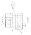
- FIG. 1 is a schematic diagram of a frame sequence
- FIG. 2 is a schematic diagram for illustrating how pixel values of an image are affected by noise interference
- FIG. 3 is a schematic diagram of a frame sequence including a moving object
- FIG. 4 is a schematic diagram for illustrating pixel values of an image that includes a moving object
- FIG. 5 is a schematic circuit block diagram of a first preferred embodiment of an image processing apparatus according to the present invention.
- FIG. 6 is a schematic diagram used to describe an example of pixel difference matrix calculation according to the first preferred embodiment of the present invention.
- FIG. 7 is a schematic diagram for illustrating a sampling window of a pixel
- FIG. 8 is a schematic diagram for illustrating different pixel differences in a pixel difference matrix
- FIG. 9 is a schematic diagram of a field sequence
- FIG. 10 is a schematic diagram of an upper field sequence and a lower field sequence
- FIG. 11 is a schematic circuit block diagram of a fourth preferred embodiment of an image processing apparatus according to the present invention.
- FIG. 12 is a schematic diagram used to describe an example of pixel difference matrix calculation in the sixth preferred embodiment of an image processing apparatus according to the present invention.
- FIG. 13 is a flowchart of the preferred embodiment of an image processing method according to the present invention.
- the first preferred embodiment of an image processing apparatus 8 comprises a pixel difference calculator 81 , a split summing unit 82 , a noise determining unit 83 , and an output unit 84 .
- the pixel difference calculator 81 receives a present image 811 and a previous image 812 .
- Each of the present image 811 and the previous image 812 is a frame and has a plurality of pixels.
- Each pixel has a pixel value, which includes a luma and a chroma.
- the pixel difference calculator 81 calculates a pixel difference between pixel values of the pair of pixels, and collects all the pixel differences to form a pixel difference matrix 813 .
- An example is provided with reference to FIG. 6 .
- the pixel difference calculator 81 when the pixel difference calculator 81 is configured to subtract pixel values of pixels of the previous image 812 from pixel values of corresponding pixels of the present image 811 , then the pixel difference matrix 813 is the result.
- the pixel difference calculator 81 when the pixel difference calculator 81 is configured to subtract pixels values of pixels of the present image 811 from pixel values of corresponding pixels of the previous image 812 , then the pixel difference matrix 813 ′ is the result.
- the split summing unit 82 includes a demultiplexer 821 , a positive pixel difference summing element 822 , and a negative pixel difference summing element 823 .
- the split summing unit 82 establishes a sampling window centered about each pixel difference and of a predetermined sampling window size. For example, referring to FIG. 7 , assuming a predetermined sampling window size of 3 ⁇ 3, for pixel differences P 1 and P 2 , the corresponding sampling windows are W 1 and W 2 , respectively. For a pixel difference at a boundary, such as pixel difference P 3 , a value of “0” for portions that lie outside the image (i.e., outside the pixel difference matrix 813 ) may be used, such that a sampling window W 3 may still be established for pixel difference P 3 . Since the previous frame has the same portion that lies outside the image, the processing result remains unaffected.
- the split summing unit 82 adds the pixel differences in each sampling window according to sign. That is, for each sampling window, the demultiplexer 821 receives each pixel difference in the sampling window and determines whether the pixel difference is positive or negative. If the value of a pixel difference is positive, the demultiplexer 821 transmits the pixel difference to the positive pixel difference summing element 822 , while if the value of a pixel difference is negative, the demultiplexer 821 transmits the pixel difference to the negative pixel difference summing element 823 .
- the positive pixel difference summing element 822 adds all received positive pixel differences belonging to a sampling window so as to generate a first output value.
- the negative pixel difference summing element 823 adds all received negative pixel differences belonging to a sampling window so as to generate a second output value. It is to be noted that the negative pixel difference summing element 823 performs an unsigned operation, and hence, the second output value is also positive.
- FIGS. 6 and 8 An example is provided with reference to FIGS. 6 and 8 .
- a sampling window size is 3 ⁇ 3, and that pixel values of pixels of the present image 811 are subtracted from pixel values of corresponding pixels of the previous image 812 to thereby result in the pixel difference matrix 813 ′′.
- pixel differences A, B have sampling windows W A , W B , respectively.
- the noise determining unit 83 receives the first and second output values of each pixel difference, and selects a blended value (K) of the pixels according to a logic operation result of the first and second output values.
- the noise determining unit 83 includes a total pixel difference calculator 831 and a blended value selector 832 .
- the total pixel difference calculator 831 calculates the difference between the first and second output values of each pixel difference so as to generate a total pixel difference (D), which indicates the level of noise interference that the pixel is subjected to.
- D total pixel difference
- the blended value selector 832 receives the total pixel difference (D) of each pixel difference and determines the blended value (K) of the pixel according to the magnitude of the total pixel difference (D). In this embodiment, the blended value (K) is determined as described below.
- Three threshold values of a first threshold value TH 1 , a second threshold value TH 2 , and a third threshold value TH 3 are preset in the blended value selector 832 , in which the first threshold value TH 1 is smaller than the second threshold value TH 2 and the second threshold value TH 2 is smaller than the third threshold value TH 3 .
- the blended value (K) of the pixel difference is set to 0.8.
- the blended value (K) of the pixel difference is set to 0.5.
- the blended value (K) of the pixel difference is set to 0.2.
- the blended value selector 832 sets a blended value (K) of the pixel difference (A) to be 0.2.
- the blended value selector 832 set a blended value (K) of the pixel difference (B) to be 0.8.
- the majority of noise interference received by an image is random noise.
- Some of the pixel values in an image increase as a result of influence by random noise, while other pixel values decrease.
- a pixel receiving noise interference may have large first and second output values but typically does not have a very large total pixel difference.
- the total pixel difference is relatively large.
- the magnitude of the total pixel difference may be used to determine whether there is pixel movement or noise interference.
- the presetting of the threshold values is not limited to what has been disclosed herein. Different numbers of threshold values, or a corresponding relation shown by a continuous function or a discrete function with variables of blended values (K) and pixel differences (D) may also be used to determine the threshold values.
- the second preferred embodiment according to this invention differs from the first preferred embodiment in that the second preferred embodiment performs processing with respect to fields.
- a consecutive field sequence (F) is formed by interposing a top field, such as field (F k ⁇ 2 ) or field (F k ), between a pair of bottom fields, such as fields (F k ⁇ 1 ) and (F k+1 ).
- the present image is a kth field (or a (k+1)th field), and the previous image is a (k ⁇ 2)th field (or a (k ⁇ 1)th field). Therefore, referring to FIG. 10 , after the top field sequence (F top ) and the bottom field sequence (F bot ) are split into two independent field sequences, the image processing apparatus of this invention can be used to perform noise determination.
- the field (F k ) of the top field sequence (F top ) is the present image and the field (F k ⁇ 2 ) thereof is the previous image.
- the field (F k+1 ) of the bottom field sequence (F bot ) is the present image and the field (F k ⁇ 1 ) thereof is the previous image.
- the top field sequence (F top ) and the bottom field sequence (F bot ) can be processed separately by two image processing apparatuses in a parallel manner, or a single image processing apparatus may be used to perform processing consecutively of the top field sequence (F top ) and the bottom field sequence (F bot ) under a time-sharing scheme.
- the third preferred embodiment according to this invention differs from the first preferred embodiment in the manner in which the total pixel difference (D′) is calculated.
- the total pixel difference (D′) is calculated in this embodiment as shown in the following:
- the fourth preferred embodiment according to this invention differs from the first preferred embodiment in the manner in which the total pixel difference (D′′) is calculated.
- total pixel difference in this invention may be calculated using a function in which the first output value of each pixel difference and the corresponding second output value are used as variables, and the determination of the blended value may change according to the situation.
- the fifth preferred embodiment according to this invention differs from the first preferred embodiment in that the noise determining unit 83 further includes a comparator 833 .
- the comparator 833 receives the first output value and the second output value of each pixel difference output from the split summing unit 82 , and compares the first output value with a first threshold value and a second threshold value, in which the first threshold value is larger than the second threshold value, and similarly, compares the second output value with a third threshold value and a fourth threshold value, in which the third threshold value is larger than the fourth threshold value.
- the first output value and the second output value of the pixel difference are transmitted to the total pixel difference calculator 831 for calculation of the total pixel difference (D) of the pixel difference and determination of a corresponding blended value (K′′).
- the image processing apparatus 8 of this preferred embodiment is able to more quickly determine whether the pixel difference is caused by a moving image or noise, and can quickly determine a better blended value (K′′).
- the sixth preferred embodiment according to this invention is similar to the first preferred embodiment, but differs therewith in the implementation of the pixel difference calculator 81 .
- the pixel difference calculator 81 establishes a current sampling window using each pixel in the present image 811 as a center point, in which the size of the sampling window can be a predetermined value of m ⁇ n or set by a user.
- the pixel difference calculator 81 establishes a previous sampling window using each pixel of the previous image 812 as a center point.
- pixel value difference calculation is performed between the present sampling window of each pixel and the previous sampling window of a pixel at a corresponding location to thereby calculate a corresponding pixel difference, after which all the pixel differences are collected to form a pixel difference matrix.
- the pixels A, B have current sampling windows W A , W B and previous sampling windows W A′ , W B′ , respectively.
- the pixel difference matrices corresponding to the pixels A, B are obtained from difference calculation of the current sampling window W A and the previous sampling window W A′ , and the current sampling window W B and the previous sampling window W B′ , respectively.
- the split summing unit 82 of this embodiment adds all the pixel differences contained in all the obtained pixel difference matrices according to the signs thereof so as to generate the first and second output values.
- the preferred embodiment of an image processing method according to this invention is used to determine whether an error between present and previous images is caused by noise or a moving object in the images.
- the image processing method includes the steps as outlined below.
- step 90 a sampling window with a size m ⁇ n is established.
- step 91 a present image and a previous image are received, in which the present image is a kth frame (or a kth field) and the previous image is a (k ⁇ 1)th frame (or a (k ⁇ 1)th field).
- step 92 pixel differences are calculated between pixels at corresponding locations in the present image and the previous image, and all the pixel differences are collected so as to form a pixel difference matrix of a dimension that is identical to that of the present image or the previous image.
- step 93 using each pixel difference as a center point, a corresponding sampling window is established, after which a first output value is generated by adding up those of the positive pixel differences in the same sampling window, and a second output value is generated by adding up those of the negative pixel differences in the same sampling window.
- a total pixel difference (D) is calculated using any of the methods disclosed in the foregoing embodiments.
- the present invention is not limited with respect to the method used to calculate the total pixel difference (D).
- a blended value (K) of the pixel difference is determined according to the magnitude of the total pixel difference (D), in which the determination of the blended value (K) is performed by any of the methods disclosed in the foregoing embodiments.
- an output pixel is calculated according to the blended value (K) of each pixel, and after the output pixel corresponding to each pixel is calculated, the output pixels are collected to form an output image is formed, after which feedback of the output image is performed for use as a previous image in a subsequent calculation.
- a determination may be made quickly using the first and second output values whether the pixel difference is caused by noise or a moving image.
- step 92 may be performed as described with reference to the sixth preferred embodiment, in which a pixel difference matrix is calculated according to sampling windows, and the size of the pixel difference matrix is the same as the sampling window but not the same as the present image.
- step 93 may be performed such that the pixel differences contained in the pixel difference matrices are added according to the signs thereof so as to generate the first and second output values.
- the image processing apparatus and method of this invention are capable of differentiating between whether such a phenomenon is the result of object movement or noise interference. Therefore, the present invention makes it possible to minimize performing noise interference processing in the situation where object movement is mistaken for noise. That is, the present invention minimizes exacerbation of error produced by performing noise interference processing when the cause of differences in pixel values between present and previous images is mistaken for noise interference rather than for dynamic imaging.
Landscapes
- Engineering & Computer Science (AREA)
- Multimedia (AREA)
- Signal Processing (AREA)
- Physics & Mathematics (AREA)
- General Physics & Mathematics (AREA)
- Theoretical Computer Science (AREA)
- Image Processing (AREA)
- Picture Signal Circuits (AREA)
Abstract
Description
First output value A 1 of pixel difference A=10+8+13+8+8+2+13=62
Second output value A2 of pixel difference A=1
First output value B 1 of pixel difference B=8+8+13+20=49
Second output value B 2 of pixel difference B=1+10+4+12+9=36
Total pixel difference(D A)of pixel difference A=first output value(A 1)−second output value(A 2)=62−1=61
Total pixel difference(D B)of pixel difference B=first output value(B 1)−second output value(B 2)=49−36=13
Output pixel=pixel value of the
Output value of pixel difference(A)=36×0.8+49×0.2=38.6
Output value of pixel difference(B)=59×0.2+55×0.8=55.8
total pixel difference(D″)=|first output value+second output value|
output pixel=pixel value corresponding to present image×(1−K)+pixel value corresponding to previous image×K
Claims (12)
Applications Claiming Priority (3)
| Application Number | Priority Date | Filing Date | Title |
|---|---|---|---|
| TW097138573A TWI404408B (en) | 2008-10-07 | 2008-10-07 | Image processing apparatus and image processing method |
| TW097138573 | 2008-10-07 | ||
| TW97138573A | 2008-10-07 |
Publications (2)
| Publication Number | Publication Date |
|---|---|
| US20100085486A1 US20100085486A1 (en) | 2010-04-08 |
| US8300150B2 true US8300150B2 (en) | 2012-10-30 |
Family
ID=42075528
Family Applications (1)
| Application Number | Title | Priority Date | Filing Date |
|---|---|---|---|
| US12/573,808 Active 2030-12-19 US8300150B2 (en) | 2008-10-07 | 2009-10-05 | Image processing apparatus and method |
Country Status (2)
| Country | Link |
|---|---|
| US (1) | US8300150B2 (en) |
| TW (1) | TWI404408B (en) |
Cited By (1)
| Publication number | Priority date | Publication date | Assignee | Title |
|---|---|---|---|---|
| US20160249047A1 (en) * | 2013-10-23 | 2016-08-25 | K-WILL Corporation | Image inspection method and sound inspection method |
Families Citing this family (4)
| Publication number | Priority date | Publication date | Assignee | Title |
|---|---|---|---|---|
| US8941726B2 (en) * | 2009-12-10 | 2015-01-27 | Mitsubishi Electric Research Laboratories, Inc. | Method and system for segmenting moving objects from images using foreground extraction |
| KR20200113060A (en) * | 2019-03-20 | 2020-10-06 | 삼성디스플레이 주식회사 | Display device including touch sensor and noise elliminating method |
| CN112819872B (en) * | 2019-11-15 | 2024-05-24 | 瑞昱半导体股份有限公司 | Image processing method based on sensor characteristics |
| JP7653452B2 (en) * | 2020-11-27 | 2025-03-28 | パナソニックホールディングス株式会社 | Image processing device, image processing method, and program |
Citations (4)
| Publication number | Priority date | Publication date | Assignee | Title |
|---|---|---|---|---|
| US4240106A (en) | 1976-10-14 | 1980-12-16 | Micro Consultants, Limited | Video noise reduction |
| US6061100A (en) | 1997-09-30 | 2000-05-09 | The University Of British Columbia | Noise reduction for video signals |
| US20060188018A1 (en) * | 2005-02-22 | 2006-08-24 | Sunplus Technology Co., Ltd. | Method and system for motion estimation using chrominance information |
| US20090268096A1 (en) * | 2008-04-28 | 2009-10-29 | Siou-Shen Lin | Video processing method for determining target motion vector according to chrominance data and film mode detection method according to chrominance data |
Family Cites Families (2)
| Publication number | Priority date | Publication date | Assignee | Title |
|---|---|---|---|---|
| WO2000034920A1 (en) * | 1998-12-07 | 2000-06-15 | Koninklijke Philips Electronics N.V. | Motion vector estimation |
| US7145950B2 (en) * | 2003-07-14 | 2006-12-05 | Primax Electronics Ltd. | Method of motion vector determination in digital video compression |
-
2008
- 2008-10-07 TW TW097138573A patent/TWI404408B/en active
-
2009
- 2009-10-05 US US12/573,808 patent/US8300150B2/en active Active
Patent Citations (4)
| Publication number | Priority date | Publication date | Assignee | Title |
|---|---|---|---|---|
| US4240106A (en) | 1976-10-14 | 1980-12-16 | Micro Consultants, Limited | Video noise reduction |
| US6061100A (en) | 1997-09-30 | 2000-05-09 | The University Of British Columbia | Noise reduction for video signals |
| US20060188018A1 (en) * | 2005-02-22 | 2006-08-24 | Sunplus Technology Co., Ltd. | Method and system for motion estimation using chrominance information |
| US20090268096A1 (en) * | 2008-04-28 | 2009-10-29 | Siou-Shen Lin | Video processing method for determining target motion vector according to chrominance data and film mode detection method according to chrominance data |
Cited By (1)
| Publication number | Priority date | Publication date | Assignee | Title |
|---|---|---|---|---|
| US20160249047A1 (en) * | 2013-10-23 | 2016-08-25 | K-WILL Corporation | Image inspection method and sound inspection method |
Also Published As
| Publication number | Publication date |
|---|---|
| US20100085486A1 (en) | 2010-04-08 |
| TW201015973A (en) | 2010-04-16 |
| TWI404408B (en) | 2013-08-01 |
Similar Documents
| Publication | Publication Date | Title |
|---|---|---|
| US8160369B2 (en) | Image processing apparatus and method | |
| US7199840B2 (en) | Dynamic gray scale range adjustment apparatus and method | |
| US9240033B2 (en) | Image super-resolution reconstruction system and method | |
| US8644387B2 (en) | Motion estimation method | |
| US8417032B2 (en) | Adjustment of image luminance values using combined histogram | |
| US8699818B2 (en) | Method, system, and program for determining image quality based on pixel changes between image frames | |
| US20030086498A1 (en) | Apparatus and method of converting frame and/or field rate using adaptive motion compensation | |
| US8254454B2 (en) | Apparatus and method for reducing temporal noise | |
| US20050237316A1 (en) | Image processing method for a TFT LCD | |
| US20040160577A1 (en) | Image processing method and apparatus | |
| US8300150B2 (en) | Image processing apparatus and method | |
| US8270750B2 (en) | Image processor, display device, image processing method, and program | |
| US20130051470A1 (en) | Motion compensated frame generating apparatus and method | |
| US8385679B2 (en) | Apparatus and method for enhancing image base on luminance information of pixel | |
| US20050259185A1 (en) | Gamma correction apparatus and method capable of preventing noise boost-up | |
| US8315435B2 (en) | Image processing apparatus and method | |
| CN113068011B (en) | Image sensor, image processing method and system | |
| Someya et al. | The suppression of noise on a dithering image in LCD overdrive | |
| US20050110907A1 (en) | Apparatus and method of measuring noise in a video signal | |
| KR20130000665A (en) | Method and apparatus for detecting and compensating back light frame | |
| CN101808190B (en) | Image processing device and image processing method | |
| TWI517095B (en) | Image processing device and method thereof | |
| US7471336B2 (en) | Global motion adaptive system with motion values correction with respect to luminance level | |
| CN104954770A (en) | Image processing device and method thereof | |
| US11495162B2 (en) | Panel display optimization method, display panel, and storage medium |
Legal Events
| Date | Code | Title | Description |
|---|---|---|---|
| AS | Assignment |
Owner name: REALTEK SEMICONDUCTOR CORP.,TAIWAN Free format text: ASSIGNMENT OF ASSIGNORS INTEREST;ASSIGNORS:CHEN, CHIEN-CHEN;HSIEH, CHUN-HSING;REEL/FRAME:023684/0298 Effective date: 20091216 Owner name: REALTEK SEMICONDUCTOR CORP., TAIWAN Free format text: ASSIGNMENT OF ASSIGNORS INTEREST;ASSIGNORS:CHEN, CHIEN-CHEN;HSIEH, CHUN-HSING;REEL/FRAME:023684/0298 Effective date: 20091216 |
|
| STCF | Information on status: patent grant |
Free format text: PATENTED CASE |
|
| FPAY | Fee payment |
Year of fee payment: 4 |
|
| MAFP | Maintenance fee payment |
Free format text: PAYMENT OF MAINTENANCE FEE, 8TH YEAR, LARGE ENTITY (ORIGINAL EVENT CODE: M1552); ENTITY STATUS OF PATENT OWNER: LARGE ENTITY Year of fee payment: 8 |
|
| MAFP | Maintenance fee payment |
Free format text: PAYMENT OF MAINTENANCE FEE, 12TH YEAR, LARGE ENTITY (ORIGINAL EVENT CODE: M1553); ENTITY STATUS OF PATENT OWNER: LARGE ENTITY Year of fee payment: 12 |