US8298714B2 - Tunnel bridge with elastomeric seal for a fuel cell stack repeating unit - Google Patents
Tunnel bridge with elastomeric seal for a fuel cell stack repeating unit Download PDFInfo
- Publication number
- US8298714B2 US8298714B2 US12/057,831 US5783108A US8298714B2 US 8298714 B2 US8298714 B2 US 8298714B2 US 5783108 A US5783108 A US 5783108A US 8298714 B2 US8298714 B2 US 8298714B2
- Authority
- US
- United States
- Prior art keywords
- plate
- fuel cell
- pem fuel
- fluid
- flow field
- Prior art date
- Legal status (The legal status is an assumption and is not a legal conclusion. Google has not performed a legal analysis and makes no representation as to the accuracy of the status listed.)
- Expired - Fee Related, expires
Links
Images


Classifications
-
- H—ELECTRICITY
- H01—ELECTRIC ELEMENTS
- H01M—PROCESSES OR MEANS, e.g. BATTERIES, FOR THE DIRECT CONVERSION OF CHEMICAL ENERGY INTO ELECTRICAL ENERGY
- H01M8/00—Fuel cells; Manufacture thereof
- H01M8/24—Grouping of fuel cells, e.g. stacking of fuel cells
- H01M8/241—Grouping of fuel cells, e.g. stacking of fuel cells with solid or matrix-supported electrolytes
- H01M8/242—Grouping of fuel cells, e.g. stacking of fuel cells with solid or matrix-supported electrolytes comprising framed electrodes or intermediary frame-like gaskets
-
- H—ELECTRICITY
- H01—ELECTRIC ELEMENTS
- H01M—PROCESSES OR MEANS, e.g. BATTERIES, FOR THE DIRECT CONVERSION OF CHEMICAL ENERGY INTO ELECTRICAL ENERGY
- H01M8/00—Fuel cells; Manufacture thereof
- H01M8/02—Details
- H01M8/0271—Sealing or supporting means around electrodes, matrices or membranes
- H01M8/0273—Sealing or supporting means around electrodes, matrices or membranes with sealing or supporting means in the form of a frame
-
- H—ELECTRICITY
- H01—ELECTRIC ELEMENTS
- H01M—PROCESSES OR MEANS, e.g. BATTERIES, FOR THE DIRECT CONVERSION OF CHEMICAL ENERGY INTO ELECTRICAL ENERGY
- H01M8/00—Fuel cells; Manufacture thereof
- H01M8/02—Details
- H01M8/0271—Sealing or supporting means around electrodes, matrices or membranes
- H01M8/0276—Sealing means characterised by their form
-
- H—ELECTRICITY
- H01—ELECTRIC ELEMENTS
- H01M—PROCESSES OR MEANS, e.g. BATTERIES, FOR THE DIRECT CONVERSION OF CHEMICAL ENERGY INTO ELECTRICAL ENERGY
- H01M8/00—Fuel cells; Manufacture thereof
- H01M8/02—Details
- H01M8/0271—Sealing or supporting means around electrodes, matrices or membranes
- H01M8/028—Sealing means characterised by their material
- H01M8/0284—Organic resins; Organic polymers
-
- H—ELECTRICITY
- H01—ELECTRIC ELEMENTS
- H01M—PROCESSES OR MEANS, e.g. BATTERIES, FOR THE DIRECT CONVERSION OF CHEMICAL ENERGY INTO ELECTRICAL ENERGY
- H01M8/00—Fuel cells; Manufacture thereof
- H01M8/10—Fuel cells with solid electrolytes
- H01M2008/1095—Fuel cells with polymeric electrolytes
-
- Y—GENERAL TAGGING OF NEW TECHNOLOGICAL DEVELOPMENTS; GENERAL TAGGING OF CROSS-SECTIONAL TECHNOLOGIES SPANNING OVER SEVERAL SECTIONS OF THE IPC; TECHNICAL SUBJECTS COVERED BY FORMER USPC CROSS-REFERENCE ART COLLECTIONS [XRACs] AND DIGESTS
- Y02—TECHNOLOGIES OR APPLICATIONS FOR MITIGATION OR ADAPTATION AGAINST CLIMATE CHANGE
- Y02E—REDUCTION OF GREENHOUSE GAS [GHG] EMISSIONS, RELATED TO ENERGY GENERATION, TRANSMISSION OR DISTRIBUTION
- Y02E60/00—Enabling technologies; Technologies with a potential or indirect contribution to GHG emissions mitigation
- Y02E60/30—Hydrogen technology
- Y02E60/50—Fuel cells
Definitions
- the present invention relates to PEM fuel cells and more particularly to a seal configuration incorporated within a fuel cell stack.
- Fuel cells have been used as a power source in many applications. For example, fuel cells have been proposed for use in electrical vehicular power plants to replace internal combustion engines.
- PEM proton exchange membrane
- hydrogen is supplied to the anode of the fuel cell and oxygen is supplied as the oxidant to the cathode.
- PEM fuel cells include a membrane electrode assembly (MEA) comprising a thin, proton transmissive, non-electrically conductive, solid polymer electrolyte membrane having the anode catalyst on one face and the cathode catalyst on the opposite face.
- MEA membrane electrode assembly
- the MEA is sandwiched between a pair of non-porous, electrically conductive elements or plates which (1) serve as current collectors for the anode and cathode, and (2) contain appropriate channels and/or openings formed therein for distributing the fuel cell's gaseous reactants over the surfaces of the respective anode and cathode catalysts.
- fuel cell is typically used to refer to either a single cell or a plurality of cells (stack) depending on the context.
- a plurality of individual cells are typically bundled together to form a fuel cell stack and are commonly arranged in electrical series.
- Each cell within the stack includes the membrane electrode assembly (MEA) described earlier, and each such MEA provides its increment of voltage.
- a group of adjacent cells within the stack is referred to as a cluster.
- hydrogen (H 2 ) is the anode reactant (i.e., fuel) and oxygen is the cathode reactant (i.e., oxidant).
- the oxygen can be either a pure form (O 2 ) or air (a mixture of O 2 and N 2 ).
- the solid polymer electrolytes are typically made from ion exchange resins such as perfluorinated sulfonic acid.
- the anode/cathode typically comprises finely divided catalytic particles, which are often supported on carbon particles, and mixed with a proton conductive resin.
- the catalytic particles are typically costly precious metal particles. As such these MEAs are relatively expensive to manufacture and require certain conditions, including proper water management and humidification and control of catalyst fouling constituents such as carbon monoxide (CO), for effective operation.
- CO carbon monoxide
- the electrically conductive plates sandwiching the MEAs may contain an array of grooves in the faces thereof that define a reactant flow field for distributing the fuel cell's gaseous reactants (i.e., hydrogen and oxygen in the form of air) over the surfaces of the respective cathode and anode.
- These reactant flow fields generally include a plurality of lands that define a plurality of flow channels therebetween through which the gaseous reactants flow from a supply header at one end of the flow channels to an exhaust header at the opposite end of the flow channels.
- nonconductive gaskets or seals provide a seal and electrical insulation between the several plates of the fuel cell stack.
- the seals provide a flow path for the gaseous reactants from the supply header to the surfaces of the respective anode and cathode catalysts.
- the seals comprise a molded compliant material such as rubber.
- bridge insert pieces may be employed to provide a tunnel for communicating the reactants from the supply header to the appropriate flow field.
- a PEM fuel cell includes a first plate having a flow field for directing a first fluid along a surface thereof.
- a second plate includes a flow field for directing a second fluid along a surface thereof.
- a seal is disposed between the first plate and the second plate.
- the seal includes a plate margin defining a header aperture for delivering the first fluid to the first plate.
- the seal defines a carrier having a first side supported by the flow field of the first plate whereby the first fluid is permitted to flow directly from the first header aperture to the flow field of the first plate.
- the carrier includes a gasket arranged on a second side. The gasket precludes the first fluid from flowing directly from the header aperture to the flow field of the second plate.
- FIG. 1 is a schematic isometric exploded illustration of a PEM fuel cell stack
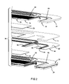
- FIG. 2 is an exploded view of a portion of the PEM fuel cell stack of FIG. 1 ;
- FIG. 3 is a detailed assembled view of the PEM fuel cell stack of FIG. 2 ;
- FIG. 4 is a partial sectional view of an assembled PEM fuel cell stack of FIG. 2 ;
- FIG. 5 is a sectional view of the PEM fuel cell stack taken along line 5 - 5 of FIG. 4 .
- FIG. 1 schematically depicts a partial PEM fuel cell stack 10 having membrane-electrode-assemblies (MEAs) 14 , 16 separated from each other by a non-porous, electrically-conductive bipolar plate 20 .
- the MEAs 14 and 16 and bipolar plate 20 are stacked together between non-porous, electrically-conductive, bipolar plates 22 and 24 .
- Porous, gas permeable, electrically conductive sheets or diffusion media 26 , 28 , 30 and 32 press up against the electrode faces of the MEAs 14 and 16 and may serve as primary current collectors for the electrodes.
- the diffusion media 26 , 28 , 30 and 32 also provide mechanical supports for the MEAs 14 and 16 , especially at locations where the MEAs are otherwise unsupported in the flow field. Suitable diffusion media include carbon/graphite paper/cloth, fine mesh noble metal screens, open cell noble metal foams, and the like which conduct current from the electrodes while allowing gas to pass therethrough.
- Bipolar plates 22 and 24 press up against the primary current collector 26 on the cathode face 14 c of the MEA 14 and the primary current collector 32 on the anode face 16 a of the MEA 16 .
- the bipolar plate 20 presses up against the primary current collector 28 on the anode face 14 a of the MEA 14 and against the primary current collector 30 on the cathode face 16 c of the MEA 16 .
- An oxidant gas such as oxygen or air is supplied to the cathode side of the fuel cell stack 10 from a storage tank 38 via appropriate supply plumbing 40 .
- a fuel such as hydrogen is supplied to the anode side of the fuel cell stack 10 from a storage tank 48 via appropriate plumbing 50 .
- the oxygen tank 38 may be eliminated, and air supplied to the cathode side from the ambient.
- the hydrogen tank 48 may be eliminated and hydrogen supplied to the anode side from a reformer which catalytically generates hydrogen from methanol or a liquid hydrocarbon (e.g., gasoline).
- Exhaust plumbing 52 for the H 2 and O 2 air sides of the MEAs is also provided for removing H 2 depleted anode gas from the anode flow field and O 2 depleted cathode gas from the cathode flow field.
- the exhaust plumbing 52 is shown as a single pipe, it is appreciated that a distinct pipe may be provided for exhausting each gas.
- the bipolar plates 20 and 22 are configured to carry a cathode reactant gas across a flow field 56 formed on a first surface and an anode reactant gas across a flow field 58 formed on a second surface.
- FIG. 2 represents a partial exploded portion 59 .
- the flow field 56 of the bipolar plate 20 communicates a cathode reactant gas to the cathode face of the MEA 14 .
- the flow field 58 of the bipolar plate 22 communicates an anode reactant gas to the anode face of the MEA 14 .
- each bipolar plate 20 , 22 and 24 are illustrated as a unitary sheet having flow fields 56 and 58 arranged on opposite faces, it is appreciated that the bipolar plates may each comprise two separator plates lying in a back to back orientation.
- the seal 60 generally comprises a carrier 62 ( FIG. 2 ) having a first elastomeric gasket 66 formed on a first side and a second elastomeric gasket 68 formed on a second side.
- the elastomeric gasket 68 on the second side is configured to seal all areas except for a bridge area 70 ( FIG. 3 ).
- the bridge area 70 while represented as a meshed area for illustrative purposes, is identified to represent an area across lands 72 of the flow field 56 near an inlet aperture 74 .
- the bridge area 70 is operable to communicate cathode reactant from the inlet header aperture 74 ( FIG. 4 ) directly to the cathode flow field 56 .
- the seal 60 is operable to provide a sealing function for respective streams of the stack (anode, cathode and coolant).
- the anode side of the gasket 66 (upper side as viewed from FIG. 2 ) is forced against the MEA 14 which in turn is forced against a first receiving channel 76 formed on the anode side of the bipolar plate 22 .
- the cathode side of the gasket 68 (lower side as viewed from FIG. 2 ) is forced against a second receiving channel 80 formed on the cathode side of the bipolar plate 20 .
- a seal is formed around the inlet and outlet apertures of the fluid headers (all not specifically shown) and around the active area on the anode side of each MEA.
- the supply header aperture 74 is defined around the inlet plate margin 84 by the respective bipolar plates 20 , 22 and 24 , MEAs 14 and seals 60 .
- the supply header aperture 74 is specifically configured to carry a cathode reactant gas in a flow direction identified generally in a vertical direction A. While not shown, it is appreciated that an anode supply header aperture is similarly formed near the outer edge of the inlet plate margin 84 .
- a complementary series of exhaust header apertures are formed on an outlet plate margin (not specifically shown) at an opposite end of the supply header.
- the carrier 62 generally comprises a polymeric film or substrate such as polyimide or polyester. Suitable materials include Kapton® (polyimide) and Mylar® (polyester) both manufactured by the E.I. DuPont Corporation.
- the polymeric substrate is molded with an elastomeric material forming the gasket. While the gasket ( 66 , 68 ) is shown molded as a double bead cross section ( FIG. 5 ), any suitable dimension may be employed. It is appreciated that these materials are merely exemplary and other materials may be similarly employed.
- the carrier 62 may alternatively comprise a metallic material or a mixture of a polymeric and metallic material.
- the seal 60 allows the cathode reactant to consist of two distinct flow segments. Specifically, the first flow segment A is defined in a generally vertical direction by the cathode inlet aperture 74 ( FIG. 4 ). The second flow segment B is defined in a generally horizontal direction defined by the cathode flow field 56 . As best illustrated in FIG. 5 , the elastomeric gasket 68 molded to the carrier 62 of the seal 60 is absent at an entrance area 88 defined on an inboard portion of the inlet header aperture 74 . As a result, direct fluid communication is permitted from the header aperture 74 to the flow field 56 . While not specifically shown, it is appreciated that the same configuration is provided with respect to the exhaust header aperture. As a result, water removal is facilitated from the cathode flow field 56 to the exhaust header aperture.
Landscapes
- Life Sciences & Earth Sciences (AREA)
- Engineering & Computer Science (AREA)
- Manufacturing & Machinery (AREA)
- Sustainable Development (AREA)
- Sustainable Energy (AREA)
- Chemical & Material Sciences (AREA)
- Chemical Kinetics & Catalysis (AREA)
- Electrochemistry (AREA)
- General Chemical & Material Sciences (AREA)
- Fuel Cell (AREA)
Abstract
Description
Claims (19)
Priority Applications (3)
| Application Number | Priority Date | Filing Date | Title |
|---|---|---|---|
| US12/057,831 US8298714B2 (en) | 2008-03-28 | 2008-03-28 | Tunnel bridge with elastomeric seal for a fuel cell stack repeating unit |
| DE102009014733.0A DE102009014733B4 (en) | 2008-03-28 | 2009-03-25 | PEM fuel cell with a seal arranged between two plates with flow fields |
| CN200910130278XA CN101546835B (en) | 2008-03-28 | 2009-03-30 | Tunnel bridge with elastomeric seal for a fuel cell stack repeating unit |
Applications Claiming Priority (1)
| Application Number | Priority Date | Filing Date | Title |
|---|---|---|---|
| US12/057,831 US8298714B2 (en) | 2008-03-28 | 2008-03-28 | Tunnel bridge with elastomeric seal for a fuel cell stack repeating unit |
Publications (2)
| Publication Number | Publication Date |
|---|---|
| US20090246599A1 US20090246599A1 (en) | 2009-10-01 |
| US8298714B2 true US8298714B2 (en) | 2012-10-30 |
Family
ID=41060825
Family Applications (1)
| Application Number | Title | Priority Date | Filing Date |
|---|---|---|---|
| US12/057,831 Expired - Fee Related US8298714B2 (en) | 2008-03-28 | 2008-03-28 | Tunnel bridge with elastomeric seal for a fuel cell stack repeating unit |
Country Status (3)
| Country | Link |
|---|---|
| US (1) | US8298714B2 (en) |
| CN (1) | CN101546835B (en) |
| DE (1) | DE102009014733B4 (en) |
Cited By (1)
| Publication number | Priority date | Publication date | Assignee | Title |
|---|---|---|---|---|
| US9431667B2 (en) | 2012-02-02 | 2016-08-30 | Ford Global Technologies, Llc | Cathode channel shutoff in a fuel cell |
Families Citing this family (4)
| Publication number | Priority date | Publication date | Assignee | Title |
|---|---|---|---|---|
| WO2011087013A1 (en) | 2010-01-14 | 2011-07-21 | 本田技研工業株式会社 | Fuel cell |
| US9484699B2 (en) * | 2014-03-13 | 2016-11-01 | Apple Inc. | Elastomeric connectors |
| CN111916809B (en) * | 2020-07-14 | 2022-04-08 | 江苏理工学院 | Self-suction paper-based microfluid fuel cell stack |
| CN112928308B (en) * | 2021-03-31 | 2022-06-14 | 华中科技大学 | Fuel cell bipolar plate for dehumidification and fuel cell stack thereof |
Citations (6)
| Publication number | Priority date | Publication date | Assignee | Title |
|---|---|---|---|---|
| US6261711B1 (en) * | 1999-09-14 | 2001-07-17 | Plug Power Inc. | Sealing system for fuel cells |
| US20010019790A1 (en) * | 1999-03-10 | 2001-09-06 | Flexfab Horizons International, Inc. | Fuel Cell Gasket Assembly and Method of Assembling Fuel Cells |
| US6500580B1 (en) * | 1998-10-07 | 2002-12-31 | Plug Power Inc. | Fuel cell fluid flow plate for promoting fluid service |
| US6524735B1 (en) * | 1999-05-18 | 2003-02-25 | Honda Giken Kogyo Kabushiki Kaisha | Fuel cell stack with a curved flow guide section |
| CN1674332A (en) | 2004-03-27 | 2005-09-28 | 现代自动车株式会社 | Unit cell structure comprising composite-gasket for fuel cell stack |
| US20060172170A1 (en) * | 2005-01-28 | 2006-08-03 | Samsung Sdi Co., Ltd. | Polymer electrolyte membrane and fuel cell using the same |
Family Cites Families (2)
| Publication number | Priority date | Publication date | Assignee | Title |
|---|---|---|---|---|
| JP3830766B2 (en) * | 2001-03-09 | 2006-10-11 | 本田技研工業株式会社 | Fuel cell and fuel cell stack |
| CN101069314A (en) * | 2004-11-30 | 2007-11-07 | 康宁股份有限公司 | Method of making a fuel cell device assembly and frame |
-
2008
- 2008-03-28 US US12/057,831 patent/US8298714B2/en not_active Expired - Fee Related
-
2009
- 2009-03-25 DE DE102009014733.0A patent/DE102009014733B4/en not_active Expired - Fee Related
- 2009-03-30 CN CN200910130278XA patent/CN101546835B/en not_active Expired - Fee Related
Patent Citations (7)
| Publication number | Priority date | Publication date | Assignee | Title |
|---|---|---|---|---|
| US6500580B1 (en) * | 1998-10-07 | 2002-12-31 | Plug Power Inc. | Fuel cell fluid flow plate for promoting fluid service |
| US20010019790A1 (en) * | 1999-03-10 | 2001-09-06 | Flexfab Horizons International, Inc. | Fuel Cell Gasket Assembly and Method of Assembling Fuel Cells |
| US6524735B1 (en) * | 1999-05-18 | 2003-02-25 | Honda Giken Kogyo Kabushiki Kaisha | Fuel cell stack with a curved flow guide section |
| US6261711B1 (en) * | 1999-09-14 | 2001-07-17 | Plug Power Inc. | Sealing system for fuel cells |
| CN1674332A (en) | 2004-03-27 | 2005-09-28 | 现代自动车株式会社 | Unit cell structure comprising composite-gasket for fuel cell stack |
| US20050214620A1 (en) | 2004-03-27 | 2005-09-29 | Cho Kyu T | Unit cell structure comprising composite-gasket for fuel cell stack |
| US20060172170A1 (en) * | 2005-01-28 | 2006-08-03 | Samsung Sdi Co., Ltd. | Polymer electrolyte membrane and fuel cell using the same |
Cited By (1)
| Publication number | Priority date | Publication date | Assignee | Title |
|---|---|---|---|---|
| US9431667B2 (en) | 2012-02-02 | 2016-08-30 | Ford Global Technologies, Llc | Cathode channel shutoff in a fuel cell |
Also Published As
| Publication number | Publication date |
|---|---|
| DE102009014733B4 (en) | 2014-02-27 |
| CN101546835B (en) | 2012-12-19 |
| US20090246599A1 (en) | 2009-10-01 |
| DE102009014733A1 (en) | 2009-10-15 |
| CN101546835A (en) | 2009-09-30 |
Similar Documents
| Publication | Publication Date | Title |
|---|---|---|
| US6974648B2 (en) | Nested bipolar plate for fuel cell and method | |
| RU2231172C2 (en) | Pile of fuel elements with membrane of polymer electrolyte | |
| US20020119358A1 (en) | Stamped bipolar plate for PEM fuel cell stack | |
| US20050064270A1 (en) | Fuel cell bipolar separator plate | |
| JP2000100457A (en) | Fuel cell | |
| US20090104476A1 (en) | Fuel cell stack with asymmetric diffusion media on anode and cathode | |
| US7186476B2 (en) | One piece bipolar plate with spring seals | |
| US20110123891A1 (en) | Membrane with optimized dimensions for a fuel cell | |
| US7318973B2 (en) | Stamped bridges and plates for reactant delivery for a fuel cell | |
| US7820335B2 (en) | Plate for a fuel cell assembly | |
| US8298714B2 (en) | Tunnel bridge with elastomeric seal for a fuel cell stack repeating unit | |
| US7592088B2 (en) | Seal configuration for fuel cell stack | |
| CA2578265C (en) | Bipolar plate having offsets | |
| CN110571449B (en) | Fuel cell stack assembly | |
| US7569299B2 (en) | Multi-component fuel cell gasket for low temperature sealing and minimal membrane contamination | |
| US7597984B2 (en) | Fuel cell bipolar plates with multiple active areas separated by non-conductive frame header | |
| JP2025111902A (en) | fuel cell stack |
Legal Events
| Date | Code | Title | Description |
|---|---|---|---|
| AS | Assignment |
Owner name: GM GLOBAL TECHNOLOGY OPERATIONS, INC., MICHIGAN Free format text: ASSIGNMENT OF ASSIGNORS INTEREST;ASSIGNOR:BEUTEL, MATTHEW J.;REEL/FRAME:020719/0834 Effective date: 20080318 |
|
| AS | Assignment |
Owner name: UNITED STATES DEPARTMENT OF THE TREASURY, DISTRICT Free format text: SECURITY AGREEMENT;ASSIGNOR:GM GLOBAL TECHNOLOGY OPERATIONS, INC.;REEL/FRAME:022195/0334 Effective date: 20081231 Owner name: UNITED STATES DEPARTMENT OF THE TREASURY,DISTRICT Free format text: SECURITY AGREEMENT;ASSIGNOR:GM GLOBAL TECHNOLOGY OPERATIONS, INC.;REEL/FRAME:022195/0334 Effective date: 20081231 |
|
| AS | Assignment |
Owner name: CITICORP USA, INC. AS AGENT FOR BANK PRIORITY SECU Free format text: SECURITY AGREEMENT;ASSIGNOR:GM GLOBAL TECHNOLOGY OPERATIONS, INC.;REEL/FRAME:022554/0479 Effective date: 20090409 Owner name: CITICORP USA, INC. AS AGENT FOR HEDGE PRIORITY SEC Free format text: SECURITY AGREEMENT;ASSIGNOR:GM GLOBAL TECHNOLOGY OPERATIONS, INC.;REEL/FRAME:022554/0479 Effective date: 20090409 |
|
| AS | Assignment |
Owner name: GM GLOBAL TECHNOLOGY OPERATIONS, INC., MICHIGAN Free format text: RELEASE BY SECURED PARTY;ASSIGNOR:UNITED STATES DEPARTMENT OF THE TREASURY;REEL/FRAME:023124/0670 Effective date: 20090709 Owner name: GM GLOBAL TECHNOLOGY OPERATIONS, INC.,MICHIGAN Free format text: RELEASE BY SECURED PARTY;ASSIGNOR:UNITED STATES DEPARTMENT OF THE TREASURY;REEL/FRAME:023124/0670 Effective date: 20090709 |
|
| AS | Assignment |
Owner name: GM GLOBAL TECHNOLOGY OPERATIONS, INC., MICHIGAN Free format text: RELEASE BY SECURED PARTY;ASSIGNORS:CITICORP USA, INC. AS AGENT FOR BANK PRIORITY SECURED PARTIES;CITICORP USA, INC. AS AGENT FOR HEDGE PRIORITY SECURED PARTIES;REEL/FRAME:023155/0880 Effective date: 20090814 Owner name: GM GLOBAL TECHNOLOGY OPERATIONS, INC.,MICHIGAN Free format text: RELEASE BY SECURED PARTY;ASSIGNORS:CITICORP USA, INC. AS AGENT FOR BANK PRIORITY SECURED PARTIES;CITICORP USA, INC. AS AGENT FOR HEDGE PRIORITY SECURED PARTIES;REEL/FRAME:023155/0880 Effective date: 20090814 |
|
| AS | Assignment |
Owner name: UNITED STATES DEPARTMENT OF THE TREASURY, DISTRICT Free format text: SECURITY AGREEMENT;ASSIGNOR:GM GLOBAL TECHNOLOGY OPERATIONS, INC.;REEL/FRAME:023156/0215 Effective date: 20090710 Owner name: UNITED STATES DEPARTMENT OF THE TREASURY,DISTRICT Free format text: SECURITY AGREEMENT;ASSIGNOR:GM GLOBAL TECHNOLOGY OPERATIONS, INC.;REEL/FRAME:023156/0215 Effective date: 20090710 |
|
| AS | Assignment |
Owner name: UAW RETIREE MEDICAL BENEFITS TRUST, MICHIGAN Free format text: SECURITY AGREEMENT;ASSIGNOR:GM GLOBAL TECHNOLOGY OPERATIONS, INC.;REEL/FRAME:023162/0187 Effective date: 20090710 Owner name: UAW RETIREE MEDICAL BENEFITS TRUST,MICHIGAN Free format text: SECURITY AGREEMENT;ASSIGNOR:GM GLOBAL TECHNOLOGY OPERATIONS, INC.;REEL/FRAME:023162/0187 Effective date: 20090710 |
|
| AS | Assignment |
Owner name: GM GLOBAL TECHNOLOGY OPERATIONS, INC., MICHIGAN Free format text: RELEASE BY SECURED PARTY;ASSIGNOR:UNITED STATES DEPARTMENT OF THE TREASURY;REEL/FRAME:025245/0780 Effective date: 20100420 |
|
| AS | Assignment |
Owner name: GM GLOBAL TECHNOLOGY OPERATIONS, INC., MICHIGAN Free format text: RELEASE BY SECURED PARTY;ASSIGNOR:UAW RETIREE MEDICAL BENEFITS TRUST;REEL/FRAME:025315/0001 Effective date: 20101026 |
|
| AS | Assignment |
Owner name: WILMINGTON TRUST COMPANY, DELAWARE Free format text: SECURITY AGREEMENT;ASSIGNOR:GM GLOBAL TECHNOLOGY OPERATIONS, INC.;REEL/FRAME:025324/0475 Effective date: 20101027 |
|
| AS | Assignment |
Owner name: GM GLOBAL TECHNOLOGY OPERATIONS LLC, MICHIGAN Free format text: CHANGE OF NAME;ASSIGNOR:GM GLOBAL TECHNOLOGY OPERATIONS, INC.;REEL/FRAME:025781/0211 Effective date: 20101202 |
|
| FEPP | Fee payment procedure |
Free format text: PAYOR NUMBER ASSIGNED (ORIGINAL EVENT CODE: ASPN); ENTITY STATUS OF PATENT OWNER: LARGE ENTITY |
|
| ZAAA | Notice of allowance and fees due |
Free format text: ORIGINAL CODE: NOA |
|
| ZAAB | Notice of allowance mailed |
Free format text: ORIGINAL CODE: MN/=. |
|
| STCF | Information on status: patent grant |
Free format text: PATENTED CASE |
|
| AS | Assignment |
Owner name: GM GLOBAL TECHNOLOGY OPERATIONS LLC, MICHIGAN Free format text: RELEASE BY SECURED PARTY;ASSIGNOR:WILMINGTON TRUST COMPANY;REEL/FRAME:034384/0758 Effective date: 20141017 |
|
| FPAY | Fee payment |
Year of fee payment: 4 |
|
| MAFP | Maintenance fee payment |
Free format text: PAYMENT OF MAINTENANCE FEE, 8TH YEAR, LARGE ENTITY (ORIGINAL EVENT CODE: M1552); ENTITY STATUS OF PATENT OWNER: LARGE ENTITY Year of fee payment: 8 |
|
| FEPP | Fee payment procedure |
Free format text: MAINTENANCE FEE REMINDER MAILED (ORIGINAL EVENT CODE: REM.); ENTITY STATUS OF PATENT OWNER: LARGE ENTITY |
|
| LAPS | Lapse for failure to pay maintenance fees |
Free format text: PATENT EXPIRED FOR FAILURE TO PAY MAINTENANCE FEES (ORIGINAL EVENT CODE: EXP.); ENTITY STATUS OF PATENT OWNER: LARGE ENTITY |
|
| STCH | Information on status: patent discontinuation |
Free format text: PATENT EXPIRED DUE TO NONPAYMENT OF MAINTENANCE FEES UNDER 37 CFR 1.362 |
|
| FP | Lapsed due to failure to pay maintenance fee |
Effective date: 20241030 |