US8256463B2 - Faucet with adjustable height spout - Google Patents
Faucet with adjustable height spout Download PDFInfo
- Publication number
- US8256463B2 US8256463B2 US12/657,974 US65797410A US8256463B2 US 8256463 B2 US8256463 B2 US 8256463B2 US 65797410 A US65797410 A US 65797410A US 8256463 B2 US8256463 B2 US 8256463B2
- Authority
- US
- United States
- Prior art keywords
- spout
- tube
- support member
- spout tube
- faucet
- Prior art date
- Legal status (The legal status is an assumption and is not a legal conclusion. Google has not performed a legal analysis and makes no representation as to the accuracy of the status listed.)
- Active, expires
Links
Images


Classifications
-
- E—FIXED CONSTRUCTIONS
- E03—WATER SUPPLY; SEWERAGE
- E03C—DOMESTIC PLUMBING INSTALLATIONS FOR FRESH WATER OR WASTE WATER; SINKS
- E03C1/00—Domestic plumbing installations for fresh water or waste water; Sinks
- E03C1/02—Plumbing installations for fresh water
- E03C1/04—Water-basin installations specially adapted to wash-basins or baths
- E03C1/0404—Constructional or functional features of the spout
-
- E—FIXED CONSTRUCTIONS
- E03—WATER SUPPLY; SEWERAGE
- E03C—DOMESTIC PLUMBING INSTALLATIONS FOR FRESH WATER OR WASTE WATER; SINKS
- E03C1/00—Domestic plumbing installations for fresh water or waste water; Sinks
- E03C1/02—Plumbing installations for fresh water
- E03C1/04—Water-basin installations specially adapted to wash-basins or baths
- E03C2001/0415—Water-basin installations specially adapted to wash-basins or baths having an extendable water outlet
-
- Y—GENERAL TAGGING OF NEW TECHNOLOGICAL DEVELOPMENTS; GENERAL TAGGING OF CROSS-SECTIONAL TECHNOLOGIES SPANNING OVER SEVERAL SECTIONS OF THE IPC; TECHNICAL SUBJECTS COVERED BY FORMER USPC CROSS-REFERENCE ART COLLECTIONS [XRACs] AND DIGESTS
- Y10—TECHNICAL SUBJECTS COVERED BY FORMER USPC
- Y10T—TECHNICAL SUBJECTS COVERED BY FORMER US CLASSIFICATION
- Y10T137/00—Fluid handling
- Y10T137/9464—Faucets and spouts
Definitions
- the present invention relates generally to faucet spouts and more particularly to a faucet spout having an adjustable height relative to a fixed base.
- FIG. 1 is a perspective view of a faucet according to the present invention at its lowest spout height set point.
- FIG. 2 is a perspective view of a faucet according to the present invention at an intermediate spout height set point.
- FIG. 3 is a perspective view of a faucet according to the present invention at its highest spout set point.
- FIG. 4 is an exploded perspective view of a faucet according to the present invention.
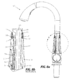
- FIG. 5 a is a partially cut-away side view of a faucet according to the present invention in which the spout is in its lowest set point as in FIG. 1 .
- FIG. 5 b is a detailed section view of the cut-away portion A of the sides view FIG. 5 a.
- FIG. 6 a is a partially cut-away side view of a faucet according to the present invention in which the spout height is being lifted to an intermediate set point as in FIG. 2 .
- FIG. 6 b is a detailed section view of the cut-away portion A of the sides view FIG. 6 a.
- FIG. 7 a is a partially cut-away side view of a faucet according to the present invention in which the spout height is at its highest set point as in FIG. 3 .
- FIG. 7 b is a detailed section view of the cut-away portion A of the sides view FIG. 7 a.
- FIG. 8 a is a partially cut-away side view of a faucet according to the present invention in which the spout height is at its highest set point as in FIG. 3 .
- FIG. 8 b is a detailed section view of the cut-away portion A of the sides view FIG. 8 a.
- FIG. 9 is detail exploded perspective view of the ratchet assembly according to the present invention.
- the invention is a faucet having an adjustable outlet height relative to a stationary base or surface to which it may be mounted.
- FIGS. 1-3 show a unitary faucet assembly generally including a spout 10 mounted atop a mixing valve body 21 , which is in turn adapted to be mounted on a stationary base or surface such as a sink.
- a flow control handle 34 is journaled into the mixing valve body for operation thereof.
- the spout 10 includes a spray head 36 , spout tube 12 and spout body 14 , and internal components (obscured) to be described.
- the spout 10 is telescopically extendable in height as progressively shown in FIGS. 1-3 and as described in detail below.
- the invention may alternately be utilized with a mixing valve body 21 and flow control handle 34 mounted separately from the spout 10 .
- Spout 10 includes a spray head 36 mounted to a spout tube 12 .
- Spray head 36 may be fixed in spout tube 12 or may be a removable wand type spray head connected by flexible hose in a conventional manner. In either spray head 36 may be connected to spout tube 12 at a circular junction to permit rotation of the spray head 36 within spout tube 12 .
- Spout tube 12 is slidably inserted into spout body 14 at a circular junction to permit both rotation and extension of the combined spout tube 12 and spray head 36 within spout body 14 . This facilitates full articulation within the spray head 36 to facilitate manipulation of water flow from the spray head 36 over a sink basin.
- spout tube 12 is an arcuate tubular member.
- the spout tube 12 is received within spout body 14 , the latter being generally cylindrical (here a fluted cylinder) and having a preferably circular top opening to cooperatively receive the cylindrical exterior surface of the spout tube 12 , which is telescopically inserted therein.
- An aperture is provided through the sidewall of the spout body 14 for exposing a release button 26 within easy access of a user in order to extend or retract the spout tube 12 , as described below.
- the spout body 14 is mounted on a valve body 32 having a flow control handle 34 journeled therein.
- the valve body 21 may be mounted to a countertop surface or sink apron (not pictured) as is generally known in the art.
- a support member 16 is fixedly mounted within the spout body 14 .
- the support member 16 is a generally cylindrical cartridge having a longitudinal void 40 extending through its length.
- the support member 16 is provided with a relieved exterior surface to permit insertion and operation of additional components (described below).
- Support member 16 is characterized by an upper portion 42 , a middle portion 44 and base portion 46 .
- the upper portion 42 of the support member 16 has a circular cross section of a diameter to be snugly received inside the spout tube 12 .
- the upper portion 42 may be ribbed with annular grooves 48 , and one or more resilient O-rings may be seated in the annular grooves 48 around the upper portion to provide a frictional dampened engagement with the inner surface of the spout tube 12 and hence smooth rotation of the spout tube 12 about the support member 16 .
- the base portion 46 of the support member 16 forms an annular flange for mounting within the spout body 14 .
- the middle portion 44 is preferably cylindrical and extends from the base portion 46 to the upper portion 42 with a recessed diameter less than that of the upper portion so as not to impede passage of the spout tube 12 .
- the spout tube 12 is, however, provided at its lower end with an annular ring 50 ( FIG. 5 b ) of reduced diameter that engages and rides on the outer surface of the middle portion 44 of the support member 16 .
- Annular ring 50 may beheld in place by a cap 52 placed over the end of the spout tube 12 .
- the annular ring 50 is preferably a split ring to facilitate installation after the spout tube 12 has been inserted over the upper portion 42 of the support member 16 .
- a cooperative partial annular ring 54 of increased radius on the external surface of the middle portion 44 of the support member 16 provides a positive stop for the spout tube 12 when retracted into the spout body 14 to its lowest position, as depicted in FIG. 5 b.
- a longitudinal slot 56 is provided extending along the outer surface of the middle portion 44 from the base portion 46 to the upper portion 42 interrupting the partial annular ring 54 .
- the longitudinal slot 56 is aligned with the sidewall release button aperture in the spout body 14 and seats a ratchet arm 18 that is pivotably affixed to the support member 16 at or near the base portion 46 .
- the ratchet arm 18 extends substantially the length of the longitudinal slot 56 and preferably pivots about a pin 61 , but may be connected by any other suitable means that permits rotation including snap-detent pin hinges or a living (flexure) hinge.
- the axis of rotation of the ratchet arm 18 is perpendicular to the longitudinal axis of the support member 16 such that the distal end of the ratchet arm 18 translates radially with respect to the support member 16 when the ratchet arm 18 is pivoted about pin 61 .
- the outside surface of the ratchet arm 18 is provided with a series of asymmetrical teeth 20 spaced lengthwise, and each characterized by a moderately sloped lower surface and a severely sloped to flat upper surface.
- a stowed position as seen in FIG. 6 b
- the entirety of the ratchet arm 18 including the teeth 20 are contained with the longitudinal slot 56 to permit passage of the spout tube annular ring 50 as the spout tube 12 is slid (lowered) downward into the spout body 14 .
- the distal end of the ratchet arm 18 extends outwardly to engage the inner surface of the spout tube 12 .
- the teeth 20 project into the path of the spout tube annular ring 50 and act as interim stops at varying elevations.
- the ratchet arm 18 is return-biased toward the deployed position by spring 63 . It should be observed that a simplified embodiment of the present invention having only two spout positions could omit the teeth 20 and utilize the distal end of the ratchet arm 18 as the single stop. In such an embodiment the annular ring 50 can be omitted as well.
- the release button 26 is affixed to the ratchet arm 18 and remains accessible through the sidewall aperture of the spout body 14 .
- the release button 26 is preferably pivotably affixed to the ratchet arm 18 by a pin 62 engaged to a yoke 19 situated below the partial annular ring 54 of the support body 16 so as not to interfere with spout tube 12 in its lowest position ( FIG. 5 b ). Depressing the release button 26 overcomes the force of the biasing spring 63 and rotates the ratchet arm 18 into the stowed position.
- This configuration leverages the ratchet arm 18 , such that actual travel of the release button 26 may be as small as 1 mm although the travel of the distal end of the ratchet arm 18 will be greater.
- the release button 26 may be rigidly affixed to the ratchet arm 18 in which case overall travel of the button 26 is increased, but in this case it becomes more difficult to seal the spout body sidewall aperture.
- the spout 10 is at its lowest position as depicted in FIG. 1 and FIGS. 5 a and 5 b .
- a user wishes to raise the spout 10 he lifts the spout tube 12 which slides up the support member 16 .
- the spout tube annular ring 50 engages the moderately sloped underside of the first tooth 20 it momentarily overcomes the force of the spring bias causing the ratchet arm 18 to rotate into the stowed position and allow the spout tube annular ring 50 to pass ( FIGS. 6 a and 6 b ).
- the ratchet arm 18 returns to the deployed position.
- the user may continue to the lift the spout tube 12 to a higher position and the ratcheting operation repeats in the same manner as the spout tube annular ring 50 engages the second or third teeth ( FIGS. 3 , 8 a and 8 B) of the ratchet arm 18 .
- the spout tube annular ring 50 prevents the spout tube 12 from being lifted past the third tooth 20 by engaging the underside of the upper portion 42 of the support member 16 .
- the upper surface of the spout tube annular ring 50 may be cooperatively sloped with respect to the moderate slope of the underside of the teeth 20 or the upper portion of the support member 16 so as to increase the contact area in order to provide more stable operation and better wear characteristics.
- the release button 26 When the user wishes to lower the spout tube 12 the release button 26 is pressed causing the ratchet arm 18 to rotate into the stowed position. As described, with the ratchet arm 18 in this position the teeth 20 are cleared from the path of the spout tube annular ring 50 and the spout tube 12 can be lowered until the release button 26 is released, at which point it will be stopped by the next encountered tooth 20 or the support member annular ring 54 in the lowest position. Rotation of the spout tube 18 is independent of and has no effect on the operation of the height adjustment system.
- the adjustable height spout body 14 is mounted directly to a valve body 32 containing an internal flow control valve of conventional construction, operatively connected to the control handle 34 .
- the spray head 36 is preferably fluidly connected to the flow control valve by flexible tubing passing through the longitudinal void 40 of the support member 16 .
- the support member 16 may be constructed so as to receive the circular spout tube within a circular central void such that the entire inside diameter of the spout tube is available for the flexible tubing. In such an embodiment an enlarged spout body may be required.
- the ratchet arm 18 may be reoriented 180° so that the teeth engage an annular ring on the outside surface of the spout tube 12 , and operation of the release would be reversed. All other elements would operate under the same principals.
Landscapes
- Health & Medical Sciences (AREA)
- Life Sciences & Earth Sciences (AREA)
- Engineering & Computer Science (AREA)
- Hydrology & Water Resources (AREA)
- Public Health (AREA)
- Water Supply & Treatment (AREA)
- Domestic Plumbing Installations (AREA)
- Mechanically-Actuated Valves (AREA)
Abstract
Description
Claims (20)
Priority Applications (4)
| Application Number | Priority Date | Filing Date | Title |
|---|---|---|---|
| US12/657,974 US8256463B2 (en) | 2010-01-29 | 2010-01-29 | Faucet with adjustable height spout |
| PCT/US2011/022866 WO2012138316A1 (en) | 2010-01-29 | 2011-01-28 | Faucet with adjustable height spout |
| CN201180017183.2A CN102859085B (en) | 2010-01-29 | 2011-01-28 | Faucet with adjustable height spout |
| CA 2787869 CA2787869A1 (en) | 2010-01-29 | 2011-01-28 | Faucet with adjustable height spout |
Applications Claiming Priority (1)
| Application Number | Priority Date | Filing Date | Title |
|---|---|---|---|
| US12/657,974 US8256463B2 (en) | 2010-01-29 | 2010-01-29 | Faucet with adjustable height spout |
Publications (2)
| Publication Number | Publication Date |
|---|---|
| US20110186162A1 US20110186162A1 (en) | 2011-08-04 |
| US8256463B2 true US8256463B2 (en) | 2012-09-04 |
Family
ID=44340576
Family Applications (1)
| Application Number | Title | Priority Date | Filing Date |
|---|---|---|---|
| US12/657,974 Active 2031-03-19 US8256463B2 (en) | 2010-01-29 | 2010-01-29 | Faucet with adjustable height spout |
Country Status (4)
| Country | Link |
|---|---|
| US (1) | US8256463B2 (en) |
| CN (1) | CN102859085B (en) |
| CA (1) | CA2787869A1 (en) |
| WO (1) | WO2012138316A1 (en) |
Cited By (18)
| Publication number | Priority date | Publication date | Assignee | Title |
|---|---|---|---|---|
| US20140159362A1 (en) * | 2012-12-10 | 2014-06-12 | Masco Corporation Of Indiana | Ratcheting hose nut for a fluid delivery device |
| USD787641S1 (en) * | 2015-10-12 | 2017-05-23 | Kohler Co. | Faucet |
| USD828907S1 (en) * | 2017-01-09 | 2018-09-18 | Quanzhou Lianchuang kitchenware and toiletry Co., Ltd. | Faucet |
| USD912780S1 (en) | 2019-08-14 | 2021-03-09 | ICG Licensing LLC | Faucet |
| USD913439S1 (en) | 2019-08-13 | 2021-03-16 | ICG Licensing LLC | Faucet |
| USD913438S1 (en) | 2019-08-13 | 2021-03-16 | ICG Licensing LLC | Faucet |
| USD914146S1 (en) | 2019-08-14 | 2021-03-23 | Kraus Usa Plumbing Llc | Faucet |
| USD914144S1 (en) | 2019-08-13 | 2021-03-23 | Kraus Usa Plumbing Llc | Faucet |
| USD914145S1 (en) | 2019-08-14 | 2021-03-23 | Kraus Usa Plumbing Llc | Faucet |
| USD914143S1 (en) | 2019-08-08 | 2021-03-23 | Kraus Usa Plumbing Llc | Faucet |
| USD944926S1 (en) * | 2020-10-12 | 2022-03-01 | Delta Faucet Company | Faucet sprayhead |
| USD944927S1 (en) * | 2020-10-12 | 2022-03-01 | Delta Faucet Company | Faucet sprayhead |
| USD954904S1 (en) * | 2020-05-11 | 2022-06-14 | Hansgrohe Se | Faucet |
| USD959607S1 (en) * | 2020-05-11 | 2022-08-02 | Hansgrohe Se | Faucet |
| USD963113S1 (en) * | 2020-05-11 | 2022-09-06 | Hansgrohe Se | Faucet |
| USD996571S1 (en) | 2020-09-24 | 2023-08-22 | Kraus Usa Plumbing Llc | Faucet |
| USD1034914S1 (en) * | 2022-09-05 | 2024-07-09 | Globe Union Industrial Corp. | Faucet |
| USD1034913S1 (en) * | 2022-08-08 | 2024-07-09 | Xiamen Forbetter Sanitary Ware Co., Ltd. | Kitchen faucet |
Families Citing this family (10)
| Publication number | Priority date | Publication date | Assignee | Title |
|---|---|---|---|---|
| CN202913467U (en) * | 2012-09-17 | 2013-05-01 | 成霖企业股份有限公司 | Fixing structure of faucet |
| CN103453197B (en) * | 2013-08-28 | 2015-07-15 | 九牧厨卫股份有限公司 | Faucet capable of adjusting water discharging height |
| CN103953773B (en) * | 2014-05-27 | 2016-04-20 | 厦门建霖工业有限公司 | A kind of tap water outlet structure |
| DE102017101900B4 (en) * | 2017-01-31 | 2025-04-03 | Oras Oy | Sanitary fitting and seal for fastening in a through hole of a sanitary installation |
| USD914844S1 (en) * | 2019-02-11 | 2021-03-30 | Delta Faucet Company | Faucet |
| CN210461300U (en) * | 2019-04-25 | 2020-05-05 | 宁波普友尔电器科技有限公司 | Water tap structure for tea bar machine |
| KR102922680B1 (en) * | 2020-01-28 | 2026-02-04 | 삼성전자주식회사 | Water Purifier |
| USD944925S1 (en) * | 2020-08-13 | 2022-03-01 | Delta Faucet Company | Faucet sprayhead |
| USD958296S1 (en) * | 2020-12-08 | 2022-07-19 | Delta Faucet Company | Faucet body |
| CN116043966B (en) * | 2023-02-10 | 2026-02-27 | 箭牌家居集团股份有限公司 | Pull-out suspension mechanism and pull-out faucet |
Citations (12)
| Publication number | Priority date | Publication date | Assignee | Title |
|---|---|---|---|---|
| US1360382A (en) * | 1920-03-19 | 1920-11-30 | Arthur Sparrow | Barber's and hair-dresser's shampco and hair-washing device |
| US2754137A (en) * | 1950-03-09 | 1956-07-10 | Gine Miguel | Adjustable water supply unit for washstands and the like |
| US4457342A (en) * | 1982-06-01 | 1984-07-03 | Stanadyne, Inc. | High rise kitchen spout |
| WO1987006861A1 (en) | 1986-05-14 | 1987-11-19 | Masco Corporation | A faucet with an adjustable spout |
| US5135173A (en) | 1991-04-19 | 1992-08-04 | Cho Wang M | Multiply adjustable faucet device |
| US5871029A (en) * | 1996-02-28 | 1999-02-16 | Peteri; Henri Bernard | Hot water tap |
| US6273138B1 (en) | 2000-05-12 | 2001-08-14 | James L. Yoney | Adjustable faucet assembly |
| US6394133B1 (en) | 1998-05-26 | 2002-05-28 | Masco Corporation Of India | Faucet with adjustable delivery spout and operating lever |
| JP3382568B2 (en) | 1999-09-24 | 2003-03-04 | 健治 大塚 | Vertical and horizontal adjustable faucet |
| US20060180222A1 (en) | 2005-02-12 | 2006-08-17 | Hyon Jin Jeung | Mesh-type angle-adjustable faucet |
| US7389796B2 (en) | 2004-02-13 | 2008-06-24 | Masco Corporation Of Indiana | Hidden faucet |
| US20100116370A1 (en) * | 2007-02-21 | 2010-05-13 | Neoperl Gmbh | Telescoping Water Outlet |
Family Cites Families (10)
| Publication number | Priority date | Publication date | Assignee | Title |
|---|---|---|---|---|
| US4553277A (en) * | 1983-11-30 | 1985-11-19 | Duncan Ronnie J | Faucet and clamping mechanism |
| US4771485A (en) * | 1986-05-23 | 1988-09-20 | Traylor Paul L | Faucet fixture |
| US5011084A (en) * | 1989-09-07 | 1991-04-30 | Toland Jonathan S | Garden hose spout |
| JP4151817B2 (en) * | 2000-09-07 | 2008-09-17 | 株式会社Inax | Water discharge device |
| CN2464795Y (en) * | 2001-02-19 | 2001-12-12 | 刘喜胜 | Universal extendible water tap |
| US6381770B1 (en) * | 2001-02-23 | 2002-05-07 | Kevin Norman Raisch | Extendable bathtub spout |
| US6588453B2 (en) * | 2001-05-15 | 2003-07-08 | Masco Corporation | Anti-wobble spray head for pull-out faucet |
| CN2791419Y (en) * | 2004-09-06 | 2006-06-28 | 鹤山市永超卫浴实业有限公司 | Kitchen water tap with spraying nozzle |
| CN2876490Y (en) * | 2006-01-25 | 2007-03-07 | 周华松 | Automatic lifting hydrovalve |
| US20070251590A1 (en) * | 2006-05-01 | 2007-11-01 | Hal Weinstein | Dual articulated faucet for lavatory bowls |
-
2010
- 2010-01-29 US US12/657,974 patent/US8256463B2/en active Active
-
2011
- 2011-01-28 CA CA 2787869 patent/CA2787869A1/en not_active Abandoned
- 2011-01-28 CN CN201180017183.2A patent/CN102859085B/en not_active Expired - Fee Related
- 2011-01-28 WO PCT/US2011/022866 patent/WO2012138316A1/en not_active Ceased
Patent Citations (12)
| Publication number | Priority date | Publication date | Assignee | Title |
|---|---|---|---|---|
| US1360382A (en) * | 1920-03-19 | 1920-11-30 | Arthur Sparrow | Barber's and hair-dresser's shampco and hair-washing device |
| US2754137A (en) * | 1950-03-09 | 1956-07-10 | Gine Miguel | Adjustable water supply unit for washstands and the like |
| US4457342A (en) * | 1982-06-01 | 1984-07-03 | Stanadyne, Inc. | High rise kitchen spout |
| WO1987006861A1 (en) | 1986-05-14 | 1987-11-19 | Masco Corporation | A faucet with an adjustable spout |
| US5135173A (en) | 1991-04-19 | 1992-08-04 | Cho Wang M | Multiply adjustable faucet device |
| US5871029A (en) * | 1996-02-28 | 1999-02-16 | Peteri; Henri Bernard | Hot water tap |
| US6394133B1 (en) | 1998-05-26 | 2002-05-28 | Masco Corporation Of India | Faucet with adjustable delivery spout and operating lever |
| JP3382568B2 (en) | 1999-09-24 | 2003-03-04 | 健治 大塚 | Vertical and horizontal adjustable faucet |
| US6273138B1 (en) | 2000-05-12 | 2001-08-14 | James L. Yoney | Adjustable faucet assembly |
| US7389796B2 (en) | 2004-02-13 | 2008-06-24 | Masco Corporation Of Indiana | Hidden faucet |
| US20060180222A1 (en) | 2005-02-12 | 2006-08-17 | Hyon Jin Jeung | Mesh-type angle-adjustable faucet |
| US20100116370A1 (en) * | 2007-02-21 | 2010-05-13 | Neoperl Gmbh | Telescoping Water Outlet |
Cited By (24)
| Publication number | Priority date | Publication date | Assignee | Title |
|---|---|---|---|---|
| US20140159362A1 (en) * | 2012-12-10 | 2014-06-12 | Masco Corporation Of Indiana | Ratcheting hose nut for a fluid delivery device |
| US9440246B2 (en) * | 2012-12-10 | 2016-09-13 | Delta Faucet Company | Ratcheting hose nut for a fluid delivery device |
| USD787641S1 (en) * | 2015-10-12 | 2017-05-23 | Kohler Co. | Faucet |
| USD797902S1 (en) | 2015-10-12 | 2017-09-19 | Kohler Co. | Faucet |
| USD812723S1 (en) * | 2015-10-12 | 2018-03-13 | Kohler Co. | Faucet |
| USD829865S1 (en) | 2015-10-12 | 2018-10-02 | Kohler Co. | Faucet |
| USD866717S1 (en) | 2015-10-12 | 2019-11-12 | Kohler Co. | Faucet |
| USD828907S1 (en) * | 2017-01-09 | 2018-09-18 | Quanzhou Lianchuang kitchenware and toiletry Co., Ltd. | Faucet |
| USD914143S1 (en) | 2019-08-08 | 2021-03-23 | Kraus Usa Plumbing Llc | Faucet |
| USD914144S1 (en) | 2019-08-13 | 2021-03-23 | Kraus Usa Plumbing Llc | Faucet |
| USD946119S1 (en) | 2019-08-13 | 2022-03-15 | Kraus Usa Plumbing Llc | Faucet |
| USD913439S1 (en) | 2019-08-13 | 2021-03-16 | ICG Licensing LLC | Faucet |
| USD913438S1 (en) | 2019-08-13 | 2021-03-16 | ICG Licensing LLC | Faucet |
| USD914146S1 (en) | 2019-08-14 | 2021-03-23 | Kraus Usa Plumbing Llc | Faucet |
| USD914145S1 (en) | 2019-08-14 | 2021-03-23 | Kraus Usa Plumbing Llc | Faucet |
| USD912780S1 (en) | 2019-08-14 | 2021-03-09 | ICG Licensing LLC | Faucet |
| USD959607S1 (en) * | 2020-05-11 | 2022-08-02 | Hansgrohe Se | Faucet |
| USD954904S1 (en) * | 2020-05-11 | 2022-06-14 | Hansgrohe Se | Faucet |
| USD963113S1 (en) * | 2020-05-11 | 2022-09-06 | Hansgrohe Se | Faucet |
| USD996571S1 (en) | 2020-09-24 | 2023-08-22 | Kraus Usa Plumbing Llc | Faucet |
| USD944927S1 (en) * | 2020-10-12 | 2022-03-01 | Delta Faucet Company | Faucet sprayhead |
| USD944926S1 (en) * | 2020-10-12 | 2022-03-01 | Delta Faucet Company | Faucet sprayhead |
| USD1034913S1 (en) * | 2022-08-08 | 2024-07-09 | Xiamen Forbetter Sanitary Ware Co., Ltd. | Kitchen faucet |
| USD1034914S1 (en) * | 2022-09-05 | 2024-07-09 | Globe Union Industrial Corp. | Faucet |
Also Published As
| Publication number | Publication date |
|---|---|
| WO2012138316A1 (en) | 2012-10-11 |
| CN102859085B (en) | 2015-05-06 |
| US20110186162A1 (en) | 2011-08-04 |
| CN102859085A (en) | 2013-01-02 |
| CA2787869A1 (en) | 2011-07-29 |
Similar Documents
| Publication | Publication Date | Title |
|---|---|---|
| US8256463B2 (en) | Faucet with adjustable height spout | |
| US10260217B2 (en) | Faucet with articulating arm | |
| JP4428343B2 (en) | Water discharge device in faucet equipment | |
| US9894879B2 (en) | Fluid dispensing bottle | |
| AU766687B2 (en) | Fluid valve | |
| EP2352695B1 (en) | A dispensing valve arrangement for a container | |
| CN107428442B (en) | Distributor for dispensing liquid to pasty materials | |
| CN101357697B (en) | bottom fillable bottle | |
| CN110449276A (en) | Take a shower head assembly | |
| US11844412B2 (en) | Cosmetic container | |
| US6367707B1 (en) | Bi-directional flow spout attachment | |
| CN104105912B (en) | Sanitary fittings | |
| US20070157981A1 (en) | Rigid mounting system for swing spouts | |
| US20110290901A1 (en) | Fountain Faucet | |
| US20070020030A1 (en) | Liquid dispensing devices including an attached cleaning element | |
| WO2019012464A1 (en) | Hydraulic tap with telescopic spout | |
| CN121368664A (en) | Faucet assembly | |
| EP2336434B1 (en) | Button assembly for activating a drain device of a flushing tank, and drain device equipped with this button assembly | |
| CN216344076U (en) | Basin tap capable of gargling | |
| JP2004225525A (en) | Hose-storage type water discharge pipe and faucet with hose-storage type water discharge pipe | |
| JP4415336B2 (en) | Faucet | |
| JP2006257740A (en) | Spouting device | |
| EP4682317A1 (en) | Fluid control shutoff valve device and sanitary fluid receptacle device | |
| KR102430778B1 (en) | Rotary type discharging direction changing apparatus for water tap | |
| JP3699015B2 (en) | Shower hose storage structure |
Legal Events
| Date | Code | Title | Description |
|---|---|---|---|
| AS | Assignment |
Owner name: NEWFREY LLC, DELAWARE Free format text: ASSIGNMENT OF ASSIGNORS INTEREST;ASSIGNORS:FARAG, HANNA O.;HANNA, AARON E.;REEL/FRAME:025651/0783 Effective date: 20110113 |
|
| AS | Assignment |
Owner name: BLACK & DECKER INC., DELAWARE Free format text: ASSIGNMENT OF ASSIGNORS INTEREST;ASSIGNOR:NEWFREY LLC;REEL/FRAME:027078/0438 Effective date: 20110930 |
|
| AS | Assignment |
Owner name: PRICE PFISTER HOLDINGS INC., DELAWARE Free format text: ASSIGNMENT OF ASSIGNORS INTEREST;ASSIGNOR:BLACK & DECKER INC.;REEL/FRAME:027103/0183 Effective date: 20110930 |
|
| AS | Assignment |
Owner name: PRICE PFISTER, INC., CALIFORNIA Free format text: ASSIGNMENT OF ASSIGNORS INTEREST;ASSIGNOR:PRICE PFISTER HOLDINGS INC.;REEL/FRAME:027107/0608 Effective date: 20111014 |
|
| STCF | Information on status: patent grant |
Free format text: PATENTED CASE |
|
| AS | Assignment |
Owner name: WELLS FARGO BANK, NATIONAL ASSOCIATION, GEORGIA Free format text: PATENT SECURITY AGREEMENT;ASSIGNORS:PRICE PFISTER, INC.;KWIKSET CORPORATION;NATIONAL MANUFACTURING CO.;REEL/FRAME:029538/0186 Effective date: 20121217 |
|
| AS | Assignment |
Owner name: BANK OF AMERICA, N.A., AS AGENT, CONNECTICUT Free format text: SECURITY AGREEMENT;ASSIGNORS:PRICE PFISTER, INC.;KWIKSET CORPORATION;NATIONAL MANUFACTURING CO.;REEL/FRAME:029731/0589 Effective date: 20121217 |
|
| AS | Assignment |
Owner name: TETRA HOLDING (US), INC., WISCONSIN Free format text: RELEASE BY SECURED PARTY;ASSIGNOR:BANK OF AMERICA, N.A., AS AGENT;REEL/FRAME:036052/0845 Effective date: 20150623 Owner name: SPECTRUM BRANDS, INC., WISCONSIN Free format text: RELEASE BY SECURED PARTY;ASSIGNOR:BANK OF AMERICA, N.A., AS AGENT;REEL/FRAME:036052/0845 Effective date: 20150623 Owner name: TELL MANUFACTURING, INC., PENNSYLVANIA Free format text: RELEASE BY SECURED PARTY;ASSIGNOR:BANK OF AMERICA, N.A., AS AGENT;REEL/FRAME:036052/0845 Effective date: 20150623 Owner name: LIQUID HOLDING COMPANY, INC., PENNSYLVANIA Free format text: RELEASE BY SECURED PARTY;ASSIGNOR:BANK OF AMERICA, N.A., AS AGENT;REEL/FRAME:036052/0845 Effective date: 20150623 Owner name: NATIONAL MANUFACTURING CO., CALIFORNIA Free format text: RELEASE BY SECURED PARTY;ASSIGNOR:BANK OF AMERICA, N.A., AS AGENT;REEL/FRAME:036052/0845 Effective date: 20150623 Owner name: ROVCAL, INC., WISCONSIN Free format text: RELEASE BY SECURED PARTY;ASSIGNOR:BANK OF AMERICA, N.A., AS AGENT;REEL/FRAME:036052/0845 Effective date: 20150623 Owner name: SEED RESOURCES, L.L.C., MICHIGAN Free format text: RELEASE BY SECURED PARTY;ASSIGNOR:BANK OF AMERICA, N.A., AS AGENT;REEL/FRAME:036052/0845 Effective date: 20150623 Owner name: SALIX ANIMAL HEALTH, LLC, FLORIDA Free format text: RELEASE BY SECURED PARTY;ASSIGNOR:BANK OF AMERICA, N.A., AS AGENT;REEL/FRAME:036052/0845 Effective date: 20150623 Owner name: RUSSELL HOBBS, INC., FLORIDA Free format text: RELEASE BY SECURED PARTY;ASSIGNOR:BANK OF AMERICA, N.A., AS AGENT;REEL/FRAME:036052/0845 Effective date: 20150623 Owner name: APPLICA CONSUMER PRODUCTS, INC., FLORIDA Free format text: RELEASE BY SECURED PARTY;ASSIGNOR:BANK OF AMERICA, N.A., AS AGENT;REEL/FRAME:036052/0845 Effective date: 20150623 Owner name: PRICE PFISTER, INC., CALIFORNIA Free format text: RELEASE BY SECURED PARTY;ASSIGNOR:BANK OF AMERICA, N.A., AS AGENT;REEL/FRAME:036052/0845 Effective date: 20150623 Owner name: TOASTMASTER INC., FLORIDA Free format text: RELEASE BY SECURED PARTY;ASSIGNOR:BANK OF AMERICA, N.A., AS AGENT;REEL/FRAME:036052/0845 Effective date: 20150623 Owner name: KWIKSET CORPORATION, CALIFORNIA Free format text: RELEASE BY SECURED PARTY;ASSIGNOR:BANK OF AMERICA, N.A., AS AGENT;REEL/FRAME:036052/0845 Effective date: 20150623 Owner name: UNITED PET GROUP, INC., WISCONSIN Free format text: RELEASE BY SECURED PARTY;ASSIGNOR:BANK OF AMERICA, N.A., AS AGENT;REEL/FRAME:036052/0845 Effective date: 20150623 |
|
| AS | Assignment |
Owner name: APPLICA CONSUMER PRODUCTS, INC., A CORP. OF FLORIDA, FLORIDA Free format text: RELEASE BY SECURED PARTY;ASSIGNOR:WELLS FARGO BANK, NATIONAL ASSOCIATION, AS COLLATERAL TRUSTEE;REEL/FRAME:036102/0001 Effective date: 20150623 Owner name: SPECTRUM BRANDS, INC. AS SUCCESSOR IN INTEREST TO ROVCAL, INC., WISCONSIN Free format text: RELEASE BY SECURED PARTY;ASSIGNOR:WELLS FARGO BANK, NATIONAL ASSOCIATION, AS COLLATERAL TRUSTEE;REEL/FRAME:036102/0001 Effective date: 20150623 Owner name: SPECTRUM BRANDS, INC., A CORP. OF DELAWARE, WISCONSIN Free format text: RELEASE BY SECURED PARTY;ASSIGNOR:WELLS FARGO BANK, NATIONAL ASSOCIATION, AS COLLATERAL TRUSTEE;REEL/FRAME:036102/0001 Effective date: 20150623 Owner name: TETRA HOLDING (US), INC., A CORP. OF DELAWARE, VIRGINIA Free format text: RELEASE BY SECURED PARTY;ASSIGNOR:WELLS FARGO BANK, NATIONAL ASSOCIATION, AS COLLATERAL TRUSTEE;REEL/FRAME:036102/0001 Effective date: 20150623 Owner name: UNITED INDUSTRIES CORPORATION AS SUCCESSOR IN INTEREST TO LIQUID HOLDING COMPANY, INC., MISSOURI Free format text: RELEASE BY SECURED PARTY;ASSIGNOR:WELLS FARGO BANK, NATIONAL ASSOCIATION, AS COLLATERAL TRUSTEE;REEL/FRAME:036102/0001 Effective date: 20150623 Owner name: UNITED PET GROUP, INC., A CORP. OF DELAWARE, WISCONSIN Free format text: RELEASE BY SECURED PARTY;ASSIGNOR:WELLS FARGO BANK, NATIONAL ASSOCIATION, AS COLLATERAL TRUSTEE;REEL/FRAME:036102/0001 Effective date: 20150623 Owner name: UNITED INDUSTRIES CORPORATION, MISSOURI Free format text: RELEASE BY SECURED PARTY;ASSIGNOR:WELLS FARGO BANK, NATIONAL ASSOCIATION, AS COLLATERAL TRUSTEE;REEL/FRAME:036102/0001 Effective date: 20150623 Owner name: TETRA HOLDINGS (US), INC., VIRGINIA Free format text: RELEASE BY SECURED PARTY;ASSIGNOR:WELLS FARGO BANK, NATIONAL ASSOCIATION, AS COLLATERAL TRUSTEE;REEL/FRAME:036102/0001 Effective date: 20150623 Owner name: APPLICA CONSUMER PRODUCTS, INC., FLORIDA Free format text: RELEASE BY SECURED PARTY;ASSIGNOR:WELLS FARGO BANK, NATIONAL ASSOCIATION, AS COLLATERAL TRUSTEE;REEL/FRAME:036102/0001 Effective date: 20150623 Owner name: PRICE PFISTER, INC., CALIFORNIA Free format text: RELEASE BY SECURED PARTY;ASSIGNOR:WELLS FARGO BANK, NATIONAL ASSOCIATION, AS COLLATERAL TRUSTEE;REEL/FRAME:036102/0001 Effective date: 20150623 Owner name: UNITED PET GROUP, INC., WISCONSIN Free format text: RELEASE BY SECURED PARTY;ASSIGNOR:WELLS FARGO BANK, NATIONAL ASSOCIATION, AS COLLATERAL TRUSTEE;REEL/FRAME:036102/0001 Effective date: 20150623 Owner name: UNITED INDUSTRIES CORPORATION AS SUCCESSOR IN INTE Free format text: RELEASE BY SECURED PARTY;ASSIGNOR:WELLS FARGO BANK, NATIONAL ASSOCIATION, AS COLLATERAL TRUSTEE;REEL/FRAME:036102/0001 Effective date: 20150623 Owner name: LIQUID HOLDING COMPANY, INC., PENNSYLVANIA Free format text: RELEASE BY SECURED PARTY;ASSIGNOR:WELLS FARGO BANK, NATIONAL ASSOCIATION, AS COLLATERAL TRUSTEE;REEL/FRAME:036102/0001 Effective date: 20150623 Owner name: UNITED PET GROUP, INC., A CORP. OF DELAWARE, WISCO Free format text: RELEASE BY SECURED PARTY;ASSIGNOR:WELLS FARGO BANK, NATIONAL ASSOCIATION, AS COLLATERAL TRUSTEE;REEL/FRAME:036102/0001 Effective date: 20150623 Owner name: ROV HOLDING, INC., A CORP. OF DELAWARE, DELAWARE Free format text: RELEASE BY SECURED PARTY;ASSIGNOR:WELLS FARGO BANK, NATIONAL ASSOCIATION, AS COLLATERAL TRUSTEE;REEL/FRAME:036102/0001 Effective date: 20150623 Owner name: APPLICA CONSUMER PRODUCTS, INC., A CORP. OF FLORID Free format text: RELEASE BY SECURED PARTY;ASSIGNOR:WELLS FARGO BANK, NATIONAL ASSOCIATION, AS COLLATERAL TRUSTEE;REEL/FRAME:036102/0001 Effective date: 20150623 Owner name: RUSSELL HOBBS, INC., A CORP. OF DELAWARE, ILLINOIS Free format text: RELEASE BY SECURED PARTY;ASSIGNOR:WELLS FARGO BANK, NATIONAL ASSOCIATION, AS COLLATERAL TRUSTEE;REEL/FRAME:036102/0001 Effective date: 20150623 Owner name: SALIX ANIMAL HEALTH, LLC, FLORIDA Free format text: RELEASE BY SECURED PARTY;ASSIGNOR:WELLS FARGO BANK, NATIONAL ASSOCIATION, AS COLLATERAL TRUSTEE;REEL/FRAME:036102/0001 Effective date: 20150623 Owner name: TETRA HOLDING (US), INC., A CORP. OF DELAWARE, VIR Free format text: RELEASE BY SECURED PARTY;ASSIGNOR:WELLS FARGO BANK, NATIONAL ASSOCIATION, AS COLLATERAL TRUSTEE;REEL/FRAME:036102/0001 Effective date: 20150623 Owner name: ROVCAL, INC., WISCONSIN Free format text: RELEASE BY SECURED PARTY;ASSIGNOR:WELLS FARGO BANK, NATIONAL ASSOCIATION, AS COLLATERAL TRUSTEE;REEL/FRAME:036102/0001 Effective date: 20150623 Owner name: SPECTRUM BRANDS, INC., WISCONSIN Free format text: RELEASE BY SECURED PARTY;ASSIGNOR:WELLS FARGO BANK, NATIONAL ASSOCIATION, AS COLLATERAL TRUSTEE;REEL/FRAME:036102/0001 Effective date: 20150623 Owner name: ROVCAL, INC., A CORP. OF CALIFORNIA, WISCONSIN Free format text: RELEASE BY SECURED PARTY;ASSIGNOR:WELLS FARGO BANK, NATIONAL ASSOCIATION, AS COLLATERAL TRUSTEE;REEL/FRAME:036102/0001 Effective date: 20150623 Owner name: TELL MANUFACTURING, INC., PENNSYLVANIA Free format text: RELEASE BY SECURED PARTY;ASSIGNOR:WELLS FARGO BANK, NATIONAL ASSOCIATION, AS COLLATERAL TRUSTEE;REEL/FRAME:036102/0001 Effective date: 20150623 Owner name: NATIONAL MANUFACTURING CO., CALIFORNIA Free format text: RELEASE BY SECURED PARTY;ASSIGNOR:WELLS FARGO BANK, NATIONAL ASSOCIATION, AS COLLATERAL TRUSTEE;REEL/FRAME:036102/0001 Effective date: 20150623 Owner name: SPECTRUM BRANDS, INC., A CORP. OF DELAWARE, WISCON Free format text: RELEASE BY SECURED PARTY;ASSIGNOR:WELLS FARGO BANK, NATIONAL ASSOCIATION, AS COLLATERAL TRUSTEE;REEL/FRAME:036102/0001 Effective date: 20150623 Owner name: KWIKSET CORPORATION, CALIFORNIA Free format text: RELEASE BY SECURED PARTY;ASSIGNOR:WELLS FARGO BANK, NATIONAL ASSOCIATION, AS COLLATERAL TRUSTEE;REEL/FRAME:036102/0001 Effective date: 20150623 Owner name: SPECTRUM BRANDS, INC. AS SUCCESSOR IN INTEREST TO Free format text: RELEASE BY SECURED PARTY;ASSIGNOR:WELLS FARGO BANK, NATIONAL ASSOCIATION, AS COLLATERAL TRUSTEE;REEL/FRAME:036102/0001 Effective date: 20150623 Owner name: SEED RESOURCES, L.L.C., MICHIGAN Free format text: RELEASE BY SECURED PARTY;ASSIGNOR:WELLS FARGO BANK, NATIONAL ASSOCIATION, AS COLLATERAL TRUSTEE;REEL/FRAME:036102/0001 Effective date: 20150623 |
|
| AS | Assignment |
Owner name: DEUTSCHE BANK AG NEW YORK BRANCH, AS COLLATERAL AGENT, NEW YORK Free format text: SECURITY INTEREST;ASSIGNOR:SPECTRUM BRANDS, INC.;REEL/FRAME:036131/0272 Effective date: 20150623 Owner name: DEUTSCHE BANK AG NEW YORK BRANCH, AS COLLATERAL AG Free format text: SECURITY INTEREST;ASSIGNOR:SPECTRUM BRANDS, INC.;REEL/FRAME:036131/0272 Effective date: 20150623 |
|
| FPAY | Fee payment |
Year of fee payment: 4 |
|
| AS | Assignment |
Owner name: SPECTRUM BRANDS, INC., WISCONSIN Free format text: MERGER;ASSIGNOR:PRICE PFISTER, INC.;REEL/FRAME:039116/0806 Effective date: 20141104 |
|
| AS | Assignment |
Owner name: ROYAL BANK OF CANADA, ONTARIO Free format text: NOTICE OF SUCCESSOR AGENT AND ASSIGNMENT OF SECURITY INTEREST (INTELLECTUAL PROPERTY) REEL/FRAME 036131/0272;ASSIGNOR:DEUTSCHE BANK AG NEW YORK BRANCH;REEL/FRAME:046301/0425 Effective date: 20180601 |
|
| MAFP | Maintenance fee payment |
Free format text: PAYMENT OF MAINTENANCE FEE, 8TH YEAR, LARGE ENTITY (ORIGINAL EVENT CODE: M1552); ENTITY STATUS OF PATENT OWNER: LARGE ENTITY Year of fee payment: 8 |
|
| AS | Assignment |
Owner name: SPECTRUM BRANDS, INC., WISCONSIN Free format text: RELEASE BY SECURED PARTY;ASSIGNOR:ROYAL BANK OF CANADA;REEL/FRAME:064029/0313 Effective date: 20230620 |
|
| AS | Assignment |
Owner name: ASSA ABLOY AMERICAS RESIDENTIAL INC., CONNECTICUT Free format text: ASSIGNMENT OF ASSIGNORS INTEREST;ASSIGNOR:SPECTRUM BRANDS, INC.;REEL/FRAME:065658/0105 Effective date: 20230620 |
|
| MAFP | Maintenance fee payment |
Free format text: PAYMENT OF MAINTENANCE FEE, 12TH YEAR, LARGE ENTITY (ORIGINAL EVENT CODE: M1553); ENTITY STATUS OF PATENT OWNER: LARGE ENTITY Year of fee payment: 12 |