US8253074B2 - Wiring assembly for an appliance - Google Patents
Wiring assembly for an appliance Download PDFInfo
- Publication number
- US8253074B2 US8253074B2 US12/329,555 US32955508A US8253074B2 US 8253074 B2 US8253074 B2 US 8253074B2 US 32955508 A US32955508 A US 32955508A US 8253074 B2 US8253074 B2 US 8253074B2
- Authority
- US
- United States
- Prior art keywords
- slide
- cable
- door
- power
- main body
- Prior art date
- Legal status (The legal status is an assumption and is not a legal conclusion. Google has not performed a legal analysis and makes no representation as to the accuracy of the status listed.)
- Active, expires
Links
Images


Classifications
-
- F—MECHANICAL ENGINEERING; LIGHTING; HEATING; WEAPONS; BLASTING
- F24—HEATING; RANGES; VENTILATING
- F24C—DOMESTIC STOVES OR RANGES ; DETAILS OF DOMESTIC STOVES OR RANGES, OF GENERAL APPLICATION
- F24C7/00—Stoves or ranges heated by electric energy
-
- H—ELECTRICITY
- H05—ELECTRIC TECHNIQUES NOT OTHERWISE PROVIDED FOR
- H05B—ELECTRIC HEATING; ELECTRIC LIGHT SOURCES NOT OTHERWISE PROVIDED FOR; CIRCUIT ARRANGEMENTS FOR ELECTRIC LIGHT SOURCES, IN GENERAL
- H05B6/00—Heating by electric, magnetic or electromagnetic fields
- H05B6/64—Heating using microwaves
- H05B6/6426—Aspects relating to the exterior of the microwave heating apparatus, e.g. metal casing, power cord
Definitions
- the present invention relates generally to a wiring assembly for an appliance. More particularly, the present invention relates to a wiring assembly that allows wiring, such as for example power and communication wiring, to have a translating motion with a door on an appliance as the door pivots open.
- the present invention is especially useful in doors having complex motions, such as for example doors that have a four-bar hinge.
- Household appliances such as ovens, often have an access door that is connected to the main body via an articulating hinge, such as a four-bar hinge. When such a door is opened, it translates away from the main body and pivots open in a compound fashion.
- the articulating four-bar hinges used in this regard create complex motions that are not accommodated by conventional wiring techniques employed with non-articulating access doors which involve single point bending of the wiring linking the access door and the main body. This is especially problematic if one wishes to locate a Human Machine Interface (HMI), such as a control panel, in the access door itself.
- HMI Human Machine Interface
- the wiring assembly includes a base attachable to the door and having a first end and a second end; a slide slidably mounted on the base so that the slide is moveable between a first position where the slide is adjacent to the first end and a second position where the slide is adjacent to the second end; a tensioning or biasing member engaging the slide with the base and biasing the slide to the first position; and a cable assembly including a power/communication cable attachable to the main body and connected to the slide.
- the wiring assembly includes a slide assembly including a base having a first end and a second end, the base being attached to the door; a slide slidably mounted on the base so that the slide is moveable between a first position where the slide is adjacent to the first end and a second position where the slide is adjacent to the second end, the slide including a first circuit board; and a tensioning or biasing member engaging the base with the slide and biasing the slide to the first position.
- the wiring assembly also includes a cable assembly including a first power/communication cable attached to the main body and operatively connected to the first circuit board.
- an appliance including a main body defining a cavity therein; a door movably attached to the main body by an articulating hinge for selectively covering the cavity, the door being pivotable about an edge thereof; a Human Machine Interface disposed in the door; a slide assembly including a base having a first end and a second end, the base being attached to the door so that the second end is closer to the edge of the door than the first end, a slide slidably mounted on the base so that the slide is moveable between a first position where the slide is adjacent to the first end and a second position where the slide is adjacent to the second end, the slide including a first circuit board operatively connected to the Human Machine Interface, and a tensioning or biasing member engaging the base with the slide and biasing the slide to the first position; and a cable assembly including a first power/communication cable attached to the main body and operatively connected to the first circuit board.
- an appliance including a main body defining a cavity therein; a door for selectively covering the cavity, the door being movably attached to the main body by an articulating hinge arrangement so that the door is movable between a closed position and an open position; a Human Machine Interface disposed in the door; a slide assembly including a base fixedly attached to the door, and a slide slidably mounted on the base for movement between a first position relatively close to the Human Machine Interface and relatively remote from the hinged edge of the door, and a second position relatively remote from the Human Machine Interface and relatively close to the hinged edge of the door; a biasing member biasing the slide to the first position; a cable assembly including a first power/communication cable, and a second power/communication cable; and a cable connector carried by the slide.
- the first power/communication cable has a first end attached to the main body and a second end operatively connected to the cable connector and the second power/communication cable having a first end operatively connected to the cable connector and a second end operatively connected to the Human Machine Interface, the second ends of the first and second power/communication cables being operatively connected to each other by the cable connector.
- the first power/communication cable is operative to move the slide from the first position to the second position as the door moves from the closed position to the open position.
- FIG. 1 is a perspective view of an exemplary appliance incorporating a wiring assembly in accordance with an embodiment of the present invention
- FIG. 2 is another perspective view of the appliance of FIG. 1 , showing the access doors are in open positions;
- FIG. 3 is an enlarged, partial, perspective view of the appliance of FIG. 1 , showing a four-part articulated hinge, the related access door, and part of the wiring assembly;
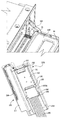
- FIG. 4A is a perspective view of the wiring assembly of FIG. 3 , showing the position of the slide relative to the base when the related access door is in a closed position;
- FIG. 4B is a perspective view of the wiring assembly of FIG. 3 , showing the position of the slide relative to the base when the related access door is in an open position;
- FIGS. 5A and 5B are perspective views, showing the elements of the slide assembly of the wiring assembly of FIG. 3 in assembled and unassembled stages;
- FIGS. 6A and 6B are perspective views, showing the elements of a cable assembly of the wiring assembly of FIG. 3 in assembled and unassembled stages;
- FIG. 7 is a perspective view, showing the door of FIG. 3 with the inner surface of the door being removed for clarity.
- FIG. 1 illustrates an exemplary appliance 10 incorporating a wiring assembly in accordance with an exemplary embodiment of the invention.
- the exemplary appliance 10 is shown as a double-cavity wall oven.
- the exemplary embodiments described herein can be used in other types of appliances including, but not limited to, single-cavity wall ovens, free standing ranges, microwave ovens.
- the appliance 10 has a main body or frame 11 that defines an upper oven cavity or chamber 12 , and a lower oven cavity or chamber 13 therein.
- the appliance 10 also has an upper access door 14 , which is movably attached to the main body 11 by a pair of hinges 15 to selectively cover the frontal opening of the upper oven cavity 12 .
- the upper access door 14 has a window 17 .
- each of the hinges 15 is a four-bar articulated hinge which both translates and pivots the door away from the frame 11 . Four-bar hinges are known in the art, and therefore will not be discussed in detail here.
- a lower access door 16 can be movably attached to the main body 11 in a similar fashion to selectively cover the frontal opening of the lower oven cavity 13 .
- the lower access door 16 has a window 18 .
- Heating elements are provided in the upper and lower oven cavities in a conventional manner.
- the HMI 20 provides the interface between a consumer and the mechanical, electronic or electromechanical control of the oven 10 .
- the HMI 20 typically includes input and output components for consumer interfacing and feedback via one or more display components.
- input components for the HMI 20 can include keys, knobs, glass touch keys (e.g., glass capacitive touch technology or field-effect switch technology), switches integrated into a membrane that can be adhered to the access door, tactile buttons that can be integrated into the access door, or knobs that can traverse through the access door.
- display components for the HMI 20 can include displays employing light emitting diodes (LEDs), vacuum fluorescent displays (VFDs), or liquid crystal displays (LCDs).
- LEDs light emitting diodes
- VFDs vacuum fluorescent displays
- LCDs liquid crystal displays
- a wiring assembly 100 in accordance with an exemplary embodiment of the present invention is used to establish a connection between the HMI 20 and electrical components mounted in the main body, e.g., relays or other switching devices (not shown) for controlling energization of heating elements or lamps (not shown) for illuminating the interior of the oven cavities, or temperature sensors monitoring the temperature in the cavities for each of the ovens.
- the wiring assembly 100 includes a slide assembly which includes a base 110 and a slide 120 .
- the access door 14 preferably includes an outer panel 14 A (see FIG. 7 ), and an inner panel 14 B (see FIG. 3 ) which is spaced apart from the outer panel 14 A.
- the base 110 has a first end 110 A, and an opposite second end 110 B.
- the base 110 is fixedly mounted to the inner surface of the outer panel 14 A with the second end 110 B being closer to the bottom edge of the access door 14 than the first end 110 A.
- the base 110 also has a pair of side guides 111 and a pair of middle guides 112 .
- the side guides 111 are on a plane which is off set from the plane defined by the middle guides 112 so that the slide 120 can be retained by, and be movable relative to the base 110 along these guides 111 , 112 between a first position where the slide 120 is adjacent to the first end 110 A ( FIG. 4A ) and a second position where the slide 120 is adjacent to the second end 110 B ( FIG. 4B ).
- a tensioning member 150 is operatively coupled between the slide 120 with the base 110 .
- the tensioning member 150 is a spring, but other tensioning devices could be similarly employed.
- the tensioning member 150 is configured to bias the slide 120 toward its first position, as shown in FIG. 4A .
- the slide 120 carries a cable connector for operatively coupling the power/communication cable which is linked to the main body to the power/communication cable which is linked to the HMI 20 as hereinafter described.
- the cable connector comprises a circuit board 130 , e.g., a printed circuit board, which has a first electrical connector 140 .
- the slide 120 also has a locking member 200 A, which in the exemplary embodiment is a snap mechanism, to lock part of a power/communication cable assembly to the slide 120 .
- the wiring assembly 100 also includes the cable assembly which includes cable 180 and housing 181 .
- the housing 181 is comprised of a bottom 190 , and a top 200 which is attached to the bottom 190 by, for example, screws. Other housing configurations are contemplated.
- the housing 181 encloses part of a second electrical connector 220 .
- the housing also encloses a second printed circuit board 210 .
- power/communication cable 180 is a ribbon cable of a predetermined length. Other wiring capable of power and/or data transmission could be similarly employed. Cable 180 is operatively coupled to the second electrical connector 220 by the second circuit board 210 .
- the other end of the cable 180 has another electrical connector 220 A for electrical connection to an electrical connector in the main body (not shown).
- the cable 180 is supported by a guide 170 .
- the guide 170 is attached to the housing 181 at a first point of attachment 170 A.
- the guide 170 is attached to the main body 11 of the oven 10 at a second point of attachment 170 B.
- the guide 170 is a thin flat sheet of a metal material that is flexible, but stiffer than the cable 180 .
- the guide 170 functions to anchor the cable 180 to the main body 11 of the oven 10 .
- the first electrical connector 140 is mated to the second electrical connector 220 such that opening of the access door 14 causes the slide 120 (carrying the first electrical connector 140 ) to translate from its first position to its second position.
- the cable assembly is connected to the slide assembly as follows: The slide 120 is moved to its second position and held in that position by a locking member, such as a snap (not shown) on either the base 110 or the slide 120 . The cable assembly is then operatively and firmly connected to the circuit board 130 by connecting the second electrical connector 220 to the first electrical connector 140 and by attaching the housing 181 to the slide 120 by the locking members 200 A. After that, the locking member between the slide 120 and the base 110 is released. The tensioning member 150 then pulls the slide 120 back to its first position.
- This movement also causes part of cable 180 to move into the access door 14 .
- the length of cable 180 is selected such that cable 180 fully extends or is in tension when the slide 120 is in its first position.
- the base 110 moves away from the main body 11 of the oven 10 .
- the slide 120 is pulled to its second position from its first position by the cable 180 when the access door 14 is opening.
- the base 110 moves closer to the main body 11 of the oven 10 and the tensioning member 150 pulls the slide 120 back to its first position. In this manner the access door 14 is allowed to sweep through an articulated motion without substantially stressing the cable 180 .
- the circuit board 130 of the slide assembly has another electrical connector 230 by which the circuit board 130 is operatively connected to a second power/communication cable 182 which is operatively coupled to the HMI 20 in the access door 14 (see FIG. 7 ).
- An exemplary HMI is discussed in detail in the commonly owned application entitled “Human-Machine Interface Assembly for an Appliance”, Ser. No. 12/329,036, filed Dec. 5, 2008, the entire content of which is incorporated herein by reference.
Landscapes
- Engineering & Computer Science (AREA)
- Chemical & Material Sciences (AREA)
- Combustion & Propulsion (AREA)
- Mechanical Engineering (AREA)
- General Engineering & Computer Science (AREA)
- Physics & Mathematics (AREA)
- Electromagnetism (AREA)
- Casings For Electric Apparatus (AREA)
Abstract
Description
Claims (20)
Priority Applications (2)
| Application Number | Priority Date | Filing Date | Title |
|---|---|---|---|
| US12/329,555 US8253074B2 (en) | 2008-12-06 | 2008-12-06 | Wiring assembly for an appliance |
| CA2663972A CA2663972A1 (en) | 2008-12-06 | 2009-04-24 | A wiring assembly for an appliance |
Applications Claiming Priority (1)
| Application Number | Priority Date | Filing Date | Title |
|---|---|---|---|
| US12/329,555 US8253074B2 (en) | 2008-12-06 | 2008-12-06 | Wiring assembly for an appliance |
Publications (2)
| Publication Number | Publication Date |
|---|---|
| US20100140247A1 US20100140247A1 (en) | 2010-06-10 |
| US8253074B2 true US8253074B2 (en) | 2012-08-28 |
Family
ID=42229923
Family Applications (1)
| Application Number | Title | Priority Date | Filing Date |
|---|---|---|---|
| US12/329,555 Active 2031-06-28 US8253074B2 (en) | 2008-12-06 | 2008-12-06 | Wiring assembly for an appliance |
Country Status (2)
| Country | Link |
|---|---|
| US (1) | US8253074B2 (en) |
| CA (1) | CA2663972A1 (en) |
Cited By (1)
| Publication number | Priority date | Publication date | Assignee | Title |
|---|---|---|---|---|
| EP4545860A1 (en) | 2023-10-24 | 2025-04-30 | LG Electronics Inc. | Home appliance |
Families Citing this family (18)
| Publication number | Priority date | Publication date | Assignee | Title |
|---|---|---|---|---|
| FR2998040B1 (en) * | 2012-11-09 | 2018-06-15 | Groupe Brandt | COOKTOP COMPRISING A CONTROL KEYBOARD |
| DE102013225407A1 (en) * | 2013-12-10 | 2015-07-02 | BSH Hausgeräte GmbH | Household appliance with a movable control panel |
| DE102014216411A1 (en) * | 2014-08-19 | 2016-02-25 | BSH Hausgeräte GmbH | Domestic appliance with a door and electrical contacts in the area of a guide of the door |
| USD772645S1 (en) * | 2014-11-13 | 2016-11-29 | Lg Electronics Inc. | Oven range |
| US10024541B2 (en) * | 2016-05-13 | 2018-07-17 | Haier Us Appliance Solutions, Inc. | Double oven appliance |
| USD880218S1 (en) * | 2017-08-24 | 2020-04-07 | Samsung Electronics Co., Ltd. | Oven |
| USD865429S1 (en) * | 2017-08-24 | 2019-11-05 | Samsung Electronics Co., Ltd. | Oven |
| US11286698B2 (en) * | 2019-06-27 | 2022-03-29 | Bsh Home Appliances Corporation | Cooking appliance having a load-bearing door |
| USD952392S1 (en) | 2019-12-27 | 2022-05-24 | Illinois Tool Works Inc. | Oven |
| USD966806S1 (en) | 2019-12-27 | 2022-10-18 | Illinois Tool Works Inc. | Oven |
| USD952402S1 (en) | 2019-12-27 | 2022-05-24 | Illinois Tool Works Inc. | Oven |
| USD932230S1 (en) | 2019-12-27 | 2021-10-05 | Illinois Tool Works Inc. | Oven |
| CN115768020B (en) * | 2022-11-24 | 2024-11-12 | 联宝(合肥)电子科技有限公司 | Four-pole guided wiring module and wiring system |
| KR20250031832A (en) * | 2023-08-29 | 2025-03-07 | 엘지전자 주식회사 | Doors for home appliance and home appliance including the same |
| KR20250031825A (en) * | 2023-08-29 | 2025-03-07 | 엘지전자 주식회사 | Doors for home appliance and home appliance including the same |
| KR20250031831A (en) * | 2023-08-29 | 2025-03-07 | 엘지전자 주식회사 | Doors for home appliance and home appliance including the same |
| KR20250031826A (en) * | 2023-08-29 | 2025-03-07 | 엘지전자 주식회사 | Doors for home appliance and home appliance including the same |
| USD1111635S1 (en) | 2023-09-06 | 2026-02-10 | Illinois Tool Works Inc. | Versatile oven |
Citations (7)
| Publication number | Priority date | Publication date | Assignee | Title |
|---|---|---|---|---|
| US4255640A (en) | 1979-10-19 | 1981-03-10 | Litton Systems, Inc. | Door mounted oven controls |
| US6300609B1 (en) | 1999-08-21 | 2001-10-09 | Lg Electronics Inc. | Door to microwave oven, control panel and cable assembly |
| US20020005014A1 (en) * | 2000-04-11 | 2002-01-17 | Kenichi Doshita | Power supply apparatus for slide door in motor vehicle |
| US20030168447A1 (en) | 2002-03-11 | 2003-09-11 | Lee Seung Ryong | Door for microwave oven |
| WO2006021936A1 (en) | 2004-08-27 | 2006-03-02 | Arcelik Anonim Sirketi | A household appliance |
| US20060219711A1 (en) * | 2005-03-29 | 2006-10-05 | Fujikura Ltd. | Power supply apparatus for sliding door |
| WO2008032903A1 (en) | 2006-09-12 | 2008-03-20 | Lg Electronics, Inc. | Cooking apparatus |
-
2008
- 2008-12-06 US US12/329,555 patent/US8253074B2/en active Active
-
2009
- 2009-04-24 CA CA2663972A patent/CA2663972A1/en not_active Abandoned
Patent Citations (12)
| Publication number | Priority date | Publication date | Assignee | Title |
|---|---|---|---|---|
| US4255640A (en) | 1979-10-19 | 1981-03-10 | Litton Systems, Inc. | Door mounted oven controls |
| US6300609B1 (en) | 1999-08-21 | 2001-10-09 | Lg Electronics Inc. | Door to microwave oven, control panel and cable assembly |
| US20020005014A1 (en) * | 2000-04-11 | 2002-01-17 | Kenichi Doshita | Power supply apparatus for slide door in motor vehicle |
| US6575760B2 (en) * | 2000-04-11 | 2003-06-10 | Yazaki Corporation | Power supply apparatus for slide door in motor vehicle |
| US20030184119A1 (en) * | 2000-04-11 | 2003-10-02 | Yazaki Corporation | Power supply apparatus for slide door in motor vehicle |
| US6811404B2 (en) * | 2000-04-11 | 2004-11-02 | Yazaki Corporation | Power supply apparatus for slide door in motor vehicle |
| US20030168447A1 (en) | 2002-03-11 | 2003-09-11 | Lee Seung Ryong | Door for microwave oven |
| WO2003077601A1 (en) | 2002-03-11 | 2003-09-18 | Lg Electronics Inc. | Door for microwave oven |
| US6984811B2 (en) | 2002-03-11 | 2006-01-10 | Lg Electronics, Inc. | Door for microwave oven having integrally formed control unit |
| WO2006021936A1 (en) | 2004-08-27 | 2006-03-02 | Arcelik Anonim Sirketi | A household appliance |
| US20060219711A1 (en) * | 2005-03-29 | 2006-10-05 | Fujikura Ltd. | Power supply apparatus for sliding door |
| WO2008032903A1 (en) | 2006-09-12 | 2008-03-20 | Lg Electronics, Inc. | Cooking apparatus |
Cited By (1)
| Publication number | Priority date | Publication date | Assignee | Title |
|---|---|---|---|---|
| EP4545860A1 (en) | 2023-10-24 | 2025-04-30 | LG Electronics Inc. | Home appliance |
Also Published As
| Publication number | Publication date |
|---|---|
| US20100140247A1 (en) | 2010-06-10 |
| CA2663972A1 (en) | 2010-06-06 |
Similar Documents
| Publication | Publication Date | Title |
|---|---|---|
| US8253074B2 (en) | Wiring assembly for an appliance | |
| US20100145483A1 (en) | Human-machine interface assembly for an appliance | |
| US6709029B2 (en) | Door latch mechanism and associated components for a self-cleaning oven | |
| CN112204217B (en) | Door handle assemblies, especially for motor vehicles | |
| US20090139052A1 (en) | Handle element | |
| EP1360446B1 (en) | Domestic appliance | |
| KR100652750B1 (en) | Handheld terminal with protective input window | |
| WO2019222705A1 (en) | Electronic oven with vertically actuated chamber door | |
| CN109904023B (en) | Knobs & Home Appliances | |
| CN107514200A (en) | Household electrical appliance | |
| JP5771854B2 (en) | Open / close switch device for vehicle sunroof | |
| CN114776151B (en) | A push-type vehicle internal opening switch | |
| US20160126952A1 (en) | Control unit for controlling electrical apparatus | |
| CN121363347A (en) | Actuating mechanism for actuating a vehicle door | |
| CN211666497U (en) | Manual-automatic integrated electric hinge | |
| CN109887791B (en) | Knob and household appliance | |
| JPS5960128A (en) | Heating device | |
| KR101449759B1 (en) | POWER WINDOW SWITCH DEVICE, POWER WINDOW SYSTEM THEREWITH, AND CONTROL METHOD THEREOF | |
| CN207529856U (en) | A kind of construction of switch and automotive back accelerator control system | |
| KR20230141528A (en) | Actuating mechanism for actuating covers for vehicles | |
| JP3498029B2 (en) | Slide switch cover | |
| US6852961B2 (en) | High frequency heating apparatus provided with a switch attachment mechansm capable of covering at least one switch from outside | |
| GB2435963A (en) | Switch assembly allowing a degree of relative movement between parts when assembled | |
| NL1044635B1 (en) | Soft push electrical switch | |
| JPH06187868A (en) | Solar remote control switch |
Legal Events
| Date | Code | Title | Description |
|---|---|---|---|
| AS | Assignment |
Owner name: GENERAL ELECTRIC COMPANY,NEW YORK Free format text: ASSIGNMENT OF ASSIGNORS INTEREST;ASSIGNORS:WATKINS, DEREK LEE;CHILTON, JOHN MARK;FROELICHER, STEVE B.;AND OTHERS;SIGNING DATES FROM 20081201 TO 20081204;REEL/FRAME:021934/0930 Owner name: GENERAL ELECTRIC COMPANY, NEW YORK Free format text: ASSIGNMENT OF ASSIGNORS INTEREST;ASSIGNORS:WATKINS, DEREK LEE;CHILTON, JOHN MARK;FROELICHER, STEVE B.;AND OTHERS;SIGNING DATES FROM 20081201 TO 20081204;REEL/FRAME:021934/0930 |
|
| STCF | Information on status: patent grant |
Free format text: PATENTED CASE |
|
| FPAY | Fee payment |
Year of fee payment: 4 |
|
| AS | Assignment |
Owner name: HAIER US APPLIANCE SOLUTIONS, INC., DELAWARE Free format text: ASSIGNMENT OF ASSIGNORS INTEREST;ASSIGNOR:GENERAL ELECTRIC COMPANY;REEL/FRAME:038966/0650 Effective date: 20160606 |
|
| MAFP | Maintenance fee payment |
Free format text: PAYMENT OF MAINTENANCE FEE, 8TH YEAR, LARGE ENTITY (ORIGINAL EVENT CODE: M1552); ENTITY STATUS OF PATENT OWNER: LARGE ENTITY Year of fee payment: 8 |
|
| MAFP | Maintenance fee payment |
Free format text: PAYMENT OF MAINTENANCE FEE, 12TH YEAR, LARGE ENTITY (ORIGINAL EVENT CODE: M1553); ENTITY STATUS OF PATENT OWNER: LARGE ENTITY Year of fee payment: 12 |