US8250962B1 - Bullet velocity enhancing rifle attachment assembly - Google Patents
Bullet velocity enhancing rifle attachment assembly Download PDFInfo
- Publication number
- US8250962B1 US8250962B1 US12/813,629 US81362910A US8250962B1 US 8250962 B1 US8250962 B1 US 8250962B1 US 81362910 A US81362910 A US 81362910A US 8250962 B1 US8250962 B1 US 8250962B1
- Authority
- US
- United States
- Prior art keywords
- aperture
- sleeve
- bullet
- central portion
- gun barrel
- Prior art date
- Legal status (The legal status is an assumption and is not a legal conclusion. Google has not performed a legal analysis and makes no representation as to the accuracy of the status listed.)
- Expired - Fee Related, expires
Links
Images


Classifications
-
- F—MECHANICAL ENGINEERING; LIGHTING; HEATING; WEAPONS; BLASTING
- F41—WEAPONS
- F41A—FUNCTIONAL FEATURES OR DETAILS COMMON TO BOTH SMALLARMS AND ORDNANCE, e.g. CANNONS; MOUNTINGS FOR SMALLARMS OR ORDNANCE
- F41A21/00—Barrels; Gun tubes; Muzzle attachments; Barrel mounting means
- F41A21/32—Muzzle attachments or glands
-
- F—MECHANICAL ENGINEERING; LIGHTING; HEATING; WEAPONS; BLASTING
- F41—WEAPONS
- F41A—FUNCTIONAL FEATURES OR DETAILS COMMON TO BOTH SMALLARMS AND ORDNANCE, e.g. CANNONS; MOUNTINGS FOR SMALLARMS OR ORDNANCE
- F41A21/00—Barrels; Gun tubes; Muzzle attachments; Barrel mounting means
- F41A21/28—Gas-expansion chambers; Barrels provided with gas-relieving ports
Definitions
- the disclosure relates to bullet velocity enhancing devices and more particularly pertains to a new bullet velocity enhancing device for increasing the speed of a bullet by utilizing the force of a bullet's pressure wave.
- An embodiment of the disclosure meets the needs presented above by generally comprising a sleeve has a first end, a second end and a perimeter wall extending between the first and second ends.
- the sleeve has an aperture therein extending into the first end and outwardly of the second end.
- the aperture is defined by an inner wall including a first portion adjacent to the first end, an second portion adjacent to the second end and a central portion positioned between the first and second portions.
- the first and second portions have a cylindrical shape.
- the central portion has an toroidal shape extending around an axis of the aperture.
- the toroidal shape has a distal edge and a proximal edge with respect to the first end.
- a coupler is attached to the second end of the sleeve.
- the coupler is releasably engageable with a gun barrel to align the aperture with the gun barrel. Pressure from a front side of a bullet traveling down the gun barrel is forced into the central portion to travel from the proximal edge to the distal edge and back into the aperture toward the first portion as the bullet travels through the central portion.
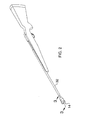
- FIG. 1 is a rear perspective view of a bullet velocity enhancing rifle attachment assembly according to an embodiment of the disclosure.
- FIG. 2 is an in-use front perspective view of an embodiment of the disclosure.
- FIG. 3A is a cross-sectional view of an embodiment of the disclosure taken along line 3 - 3 of FIG. 2 .
- FIG. 3B is a cross-sectional view of an embodiment of the disclosure.
- FIG. 3C is a cross-sectional view of an embodiment of the disclosure.
- FIG. 3D is a cross-sectional view of an embodiment of the disclosure depicting another coupler of the invention.
- FIG. 4 is a cross-sectional view of an embodiment of the disclosure taken along line 4 - 4 of FIG. 3C .
- FIGS. 1 through 4 a new bullet velocity enhancing device embodying the principles and concepts of an embodiment of the disclosure and generally designated by the reference numeral 10 will be described.
- the bullet velocity enhancing rifle attachment assembly 10 generally comprises a sleeve 12 that has a first end 14 , a second end 16 and a perimeter wall 18 extending between the first 14 and second 16 ends.
- the sleeve 12 has an aperture 20 therein extending into the first end 14 and outwardly of the second end 16 .
- the aperture 20 is defined by an inner wall.
- the inner wall includes a first portion 22 adjacent to the first end 14 , a second portion 24 adjacent to the second end 16 and a central portion 26 positioned between the first 22 and second 24 portions.
- the first 22 and second 24 portions have a cylindrical shape.
- the central portion 26 has an oblong toroidal shape, or cut-out, extending around an axis of the aperture 20 .
- the central section 15 has a cross-section taken parallel to the axis of the aperture 20 forming a pair of obrounds having curved ends and straight edges extending between the curved ends.
- the obrounds, or the toroidal shape as a whole, have a distal edge 28 and a proximal edge 30 with respect to the first end 14 .
- a coupler 30 is attached to the second end 16 of the sleeve 12 .
- the coupler 30 is releasably engageable with a gun barrel 32 to align the aperture 20 with the gun barrel 32 .
- the coupler 30 may take a variety of forms.
- FIG. 3A shows a coupler 30 including a housing 34 positioned on the barrel 32 having an inner threading 36 .
- the housing 34 has an end wall 38 and a peripheral wall 40 extending away from the end wall 38 .
- the barrel 32 is extended through the end wall 38 .
- a male coupler 42 having threading 44 thereon is attached to the second end 16 and engages the inner threading 36 positioned on the peripheral wall 40 .
- FIG. 3D shows a barrel 32 having outer threading 48 thereon.
- a female coupler 50 is attached to the second end 16 and threadably engages the outer threading 48 .
- the sleeve 12 may have a break 52 therein positioned at a juncture of the first 22 and central 26 portions to define a first section 54 and a second section 56 of the sleeve 12 . Because of the shape of the toroid, the proximal edge 30 extends into a portion of the sleeve 12 containing the first portion 22 such that the break extends through the toroid.
- the first 54 and second 56 sections are threadably coupled together. By removing the first section 54 from the second section 56 , the user of the assembly 10 can access and clean the toroidal shape.
- a bullet 33 is fired from a rifle barrel 32 in a conventional manner to send the bullet 33 down the barrel 32 .
- the bullet 33 creates a pressure wave in front of it.
- the pressure wave (as shown by the arrows within the central portion 26 ) is forced into the central portion 26 to travel from the proximal edge 30 to the distal edge 28 and back into the aperture 20 toward the first portion 22 as the bullet 33 travels through the central portion 26 .
- This pressure reintroduced behind the bullet 33 , will add force to the bullet 33 and increase its velocity.
Landscapes
- Engineering & Computer Science (AREA)
- General Engineering & Computer Science (AREA)
- Aiming, Guidance, Guns With A Light Source, Armor, Camouflage, And Targets (AREA)
Abstract
A bullet velocity enhancing rifle attachment assembly a sleeve having a first end, a second end and a perimeter wall. The sleeve has an aperture therein extending into the first end and outwardly of the second end. The aperture is defined by an inner wall including a first portion adjacent to the first end, an second portion adjacent to the second end and a central portion positioned between the first and second portions. The central portion has an toroidal shape. A coupler attached to the second end of the sleeve is releasably engageable with a gun barrel to align the aperture with the gun barrel. Pressure from a front side of a bullet traveling down the gun barrel is forced into the central portion to travel around the toroidal shape and back into the aperture toward the first portion, behind the bullet, as the bullet travels through the central portion.
Description
The disclosure relates to bullet velocity enhancing devices and more particularly pertains to a new bullet velocity enhancing device for increasing the speed of a bullet by utilizing the force of a bullet's pressure wave.
An embodiment of the disclosure meets the needs presented above by generally comprising a sleeve has a first end, a second end and a perimeter wall extending between the first and second ends. The sleeve has an aperture therein extending into the first end and outwardly of the second end. The aperture is defined by an inner wall including a first portion adjacent to the first end, an second portion adjacent to the second end and a central portion positioned between the first and second portions. The first and second portions have a cylindrical shape. The central portion has an toroidal shape extending around an axis of the aperture. The toroidal shape has a distal edge and a proximal edge with respect to the first end. A coupler is attached to the second end of the sleeve. The coupler is releasably engageable with a gun barrel to align the aperture with the gun barrel. Pressure from a front side of a bullet traveling down the gun barrel is forced into the central portion to travel from the proximal edge to the distal edge and back into the aperture toward the first portion as the bullet travels through the central portion.
There has thus been outlined, rather broadly, the more important features of the disclosure in order that the detailed description thereof that follows may be better understood, and in order that the present contribution to the art may be better appreciated. There are additional features of the disclosure that will be described hereinafter and which will form the subject matter of the claims appended hereto.
The objects of the disclosure, along with the various features of novelty which characterize the disclosure, are pointed out with particularity in the claims annexed to and forming a part of this disclosure.
The disclosure will be better understood and objects other than those set forth above will become apparent when consideration is given to the following detailed description thereof. Such description makes reference to the annexed drawings wherein:
With reference now to the drawings, and in particular to FIGS. 1 through 4 thereof, a new bullet velocity enhancing device embodying the principles and concepts of an embodiment of the disclosure and generally designated by the reference numeral 10 will be described.
As best illustrated in FIGS. 1 through 4 , the bullet velocity enhancing rifle attachment assembly 10 generally comprises a sleeve 12 that has a first end 14, a second end 16 and a perimeter wall 18 extending between the first 14 and second 16 ends. The sleeve 12 has an aperture 20 therein extending into the first end 14 and outwardly of the second end 16. The aperture 20 is defined by an inner wall. The inner wall includes a first portion 22 adjacent to the first end 14, a second portion 24 adjacent to the second end 16 and a central portion 26 positioned between the first 22 and second 24 portions. The first 22 and second 24 portions have a cylindrical shape. The central portion 26 has an oblong toroidal shape, or cut-out, extending around an axis of the aperture 20. The central section 15 has a cross-section taken parallel to the axis of the aperture 20 forming a pair of obrounds having curved ends and straight edges extending between the curved ends. The obrounds, or the toroidal shape as a whole, have a distal edge 28 and a proximal edge 30 with respect to the first end 14.
A coupler 30 is attached to the second end 16 of the sleeve 12. The coupler 30 is releasably engageable with a gun barrel 32 to align the aperture 20 with the gun barrel 32. As shown in the Figures, the coupler 30 may take a variety of forms. FIG. 3A shows a coupler 30 including a housing 34 positioned on the barrel 32 having an inner threading 36. The housing 34 has an end wall 38 and a peripheral wall 40 extending away from the end wall 38. The barrel 32 is extended through the end wall 38. A male coupler 42 having threading 44 thereon is attached to the second end 16 and engages the inner threading 36 positioned on the peripheral wall 40. An elastomeric washer 46 is urged against the end wall 38, causing it to expand toward and frictionally engage the barrel 32 to hold the sleeve 12 to the barrel 32. FIG. 3D shows a barrel 32 having outer threading 48 thereon. A female coupler 50 is attached to the second end 16 and threadably engages the outer threading 48.
As shown in FIG. 3C , the sleeve 12 may have a break 52 therein positioned at a juncture of the first 22 and central 26 portions to define a first section 54 and a second section 56 of the sleeve 12. Because of the shape of the toroid, the proximal edge 30 extends into a portion of the sleeve 12 containing the first portion 22 such that the break extends through the toroid. The first 54 and second 56 sections are threadably coupled together. By removing the first section 54 from the second section 56, the user of the assembly 10 can access and clean the toroidal shape.
In use, a bullet 33 is fired from a rifle barrel 32 in a conventional manner to send the bullet 33 down the barrel 32. The bullet 33 creates a pressure wave in front of it. As the front side of the bullet 33 travels into the sleeve 12, the pressure wave (as shown by the arrows within the central portion 26) is forced into the central portion 26 to travel from the proximal edge 30 to the distal edge 28 and back into the aperture 20 toward the first portion 22 as the bullet 33 travels through the central portion 26. This pressure, reintroduced behind the bullet 33, will add force to the bullet 33 and increase its velocity.
With respect to the above description then, it is to be realized that the optimum dimensional relationships for the parts of an embodiment enabled by the disclosure, to include variations in size, materials, shape, form, function and manner of operation, assembly and use, are deemed readily apparent and obvious to one skilled in the art, and all equivalent relationships to those illustrated in the drawings and described in the specification are intended to be encompassed by an embodiment of the disclosure.
Therefore, the foregoing is considered as illustrative only of the principles of the disclosure. Further, since numerous modifications and changes will readily occur to those skilled in the art, it is not desired to limit the disclosure to the exact construction and operation shown and described, and accordingly, all suitable modifications and equivalents may be resorted to, falling within the scope of the disclosure.
Claims (4)
1. A bullet velocity enhancing assembly being attachable to a gun barrel, said assembly including:
a sleeve having a first end, a second end and a perimeter wall extending between said first and second ends, said sleeve having an aperture therein extending into said first end and outwardly of said second end, said aperture being defined by an inner wall, said inner wall including a first portion adjacent to said first end, an second portion adjacent to said second end and a central portion positioned between said first and second portions, said first and second portions having a cylindrical shape, said central portion having an toroidal shape extending across its length and around an axis of said aperture, said toroidal shape having a distal edge and a proximal edge with respect to said first end;
a coupler being attached to said second end of said sleeve, said coupler being releasably engageable with a gun barrel to align said aperture with said gun barrel; and
wherein pressure from a front side of a bullet traveling down the gun barrel is forced into said central portion to travel from said proximal edge to said distal edge and back into said aperture toward said first portion as the bullet travels through said central portion.
2. The assembly according to clam 1, wherein said toroidal shape is oblong such that said central section has a cross-section taken parallel to said axis of said aperture forming a pair of obrounds.
3. The assembly according to clam 1, wherein said sleeve has a break therein positioned at a juncture of said first and central portions to define a first section and a second section of said sleeve, said first and second sections being threadably coupled together.
4. A bullet velocity enhancing assembly being attachable to a gun barrel, said assembly including:
a sleeve having a first end, a second end and a perimeter wall extending between said first and second ends, said sleeve having an aperture therein extending into said first end and outwardly of said second end, said aperture being defined by an inner wall, said inner wall including a first portion adjacent to said first end, an second portion adjacent to said second end and a central portion positioned between said first and second portions, said first and second portions having a cylindrical shape, said central portion having an oblong toroidal shape across its length and extending around an axis of said aperture such that said central section has a cross-section taken parallel to said axis of said aperture forming a pair of obrounds, said obrounds having a distal edge and a proximal edge with respect to said first end;
a coupler being attached to said second end of said sleeve, said coupler being releasably engageable with a gun barrel to align said aperture with said gun barrel, wherein pressure from a front side of a bullet traveling down the gun barrel is forced into said central portion to travel from said proximal edge to said distal edge and back into said aperture toward said first portion as the bullet travels through said central portion; and
said sleeve having a break therein positioned at a juncture of said first and central portions to define a first section and a second section of said sleeve, said first and second sections being threadably coupled together.
Priority Applications (1)
| Application Number | Priority Date | Filing Date | Title |
|---|---|---|---|
| US12/813,629 US8250962B1 (en) | 2010-06-11 | 2010-06-11 | Bullet velocity enhancing rifle attachment assembly |
Applications Claiming Priority (1)
| Application Number | Priority Date | Filing Date | Title |
|---|---|---|---|
| US12/813,629 US8250962B1 (en) | 2010-06-11 | 2010-06-11 | Bullet velocity enhancing rifle attachment assembly |
Publications (1)
| Publication Number | Publication Date |
|---|---|
| US8250962B1 true US8250962B1 (en) | 2012-08-28 |
Family
ID=46689642
Family Applications (1)
| Application Number | Title | Priority Date | Filing Date |
|---|---|---|---|
| US12/813,629 Expired - Fee Related US8250962B1 (en) | 2010-06-11 | 2010-06-11 | Bullet velocity enhancing rifle attachment assembly |
Country Status (1)
| Country | Link |
|---|---|
| US (1) | US8250962B1 (en) |
Cited By (12)
| Publication number | Priority date | Publication date | Assignee | Title |
|---|---|---|---|---|
| USD678453S1 (en) * | 2011-03-08 | 2013-03-19 | Blaser Finanzholding Gmbh | Rifle |
| US20150184960A1 (en) * | 2013-12-31 | 2015-07-02 | Sergey Monveldt | Muzzle Device for Firearm Having a Gas Operating System |
| US9709355B2 (en) * | 2014-12-15 | 2017-07-18 | Jered S. Joplin | Recoil compensator for firearm |
| US9885533B2 (en) * | 2016-03-10 | 2018-02-06 | James Norman Griffitts | Barrel stabalizing and recoil reducing muzzle brake |
| US20180172383A1 (en) * | 2016-12-15 | 2018-06-21 | Palmetto State Defense, LLC | Suppressor For A Firearm |
| US10422603B2 (en) | 2016-03-10 | 2019-09-24 | James Norman Griffitts | Barrel stabilizing and recoil reducing muzzle brake |
| RU2733186C1 (en) * | 2020-02-21 | 2020-09-29 | Андрей Юлиусович Фот | Barrel for firearms |
| US10816300B2 (en) * | 2016-03-10 | 2020-10-27 | James Norman Griffitts | Barrel stabilizing and recoil reducing muzzle brake |
| US11280572B2 (en) | 2016-03-10 | 2022-03-22 | James Norman Griffitts | Barrel stabilizing and recoil reducing muzzle brake with guiding ribs |
| US20230175797A1 (en) * | 2021-12-08 | 2023-06-08 | David J. Dawson, JR. | Pistol Compensator Components, Systems, and Methods |
| US12163750B2 (en) | 2021-02-12 | 2024-12-10 | James Norman Griffitts | Sound suppressor with adapter for use with muzzle accessory |
| USD1097039S1 (en) | 2022-12-07 | 2025-10-07 | David J. Dawson, JR. | Pistol compensator |
Citations (19)
| Publication number | Priority date | Publication date | Assignee | Title |
|---|---|---|---|---|
| US1939700A (en) * | 1932-06-17 | 1933-12-19 | Clarence F Hofstetter | Muzzle attachment for guns |
| US2075837A (en) * | 1936-06-03 | 1937-04-06 | Rene R Studler | Blank ammunition firing attachment for automatic guns |
| US2150161A (en) * | 1936-10-16 | 1939-03-14 | Samuel G Green | Muzzle attachment for guns |
| US3707899A (en) * | 1970-07-29 | 1973-01-02 | W Perrine | Firearm muzzle deflector |
| US4058925A (en) * | 1976-09-01 | 1977-11-22 | Remington Arms Company, Inc. | Concepts of remington super trap choke |
| US4368589A (en) * | 1979-08-28 | 1983-01-18 | Costa Anthony A | Hand gun and kit therefor |
| US4527348A (en) * | 1984-01-27 | 1985-07-09 | D. C. Brennan Firearms, Inc. | Gun barrel |
| US4579037A (en) * | 1984-02-13 | 1986-04-01 | Weapon Technology Systems R & D, Ltd. | Machine pistol with retarded blowback |
| US4590698A (en) * | 1982-11-18 | 1986-05-27 | Finn Charles A | Barrel bypass system--full length groove |
| US4681016A (en) | 1984-05-02 | 1987-07-21 | Ga Technologies Inc. | Rail gun barrel with gas containment means |
| US4691614A (en) * | 1986-05-30 | 1987-09-08 | Leffel Leon E | Nonsymmetrical compensator for handgun |
| US4813333A (en) * | 1983-12-12 | 1989-03-21 | Accura Technology Corporation | Dually-adjustable firearm muzzle attachment device |
| US5097614A (en) | 1990-05-01 | 1992-03-24 | Strong B Gene | Riot gun |
| US5992291A (en) * | 1997-11-10 | 1999-11-30 | Widder; Jeffrey Michael | Variable velocity weapons having selective lethality and methods related thereto |
| US6112447A (en) * | 1998-09-11 | 2000-09-05 | B.B.A. Research & Development, Inc | Shotgun choke |
| US6302009B1 (en) * | 1997-11-21 | 2001-10-16 | O'quinn Carl L. | Gun noise and recoil suppressor |
| US20030024377A1 (en) | 2001-08-03 | 2003-02-06 | Diller E. Wendell | Elongated vented gun barrel |
| US20030154849A1 (en) | 2002-02-21 | 2003-08-21 | Heinz-Gunter Breuer | Gun barrel having a muzzle brake |
| USD592271S1 (en) | 2006-05-12 | 2009-05-12 | Industrias El Gamo, S.A. | Barrel for sporting rifles and firearms |
-
2010
- 2010-06-11 US US12/813,629 patent/US8250962B1/en not_active Expired - Fee Related
Patent Citations (20)
| Publication number | Priority date | Publication date | Assignee | Title |
|---|---|---|---|---|
| US1939700A (en) * | 1932-06-17 | 1933-12-19 | Clarence F Hofstetter | Muzzle attachment for guns |
| US2075837A (en) * | 1936-06-03 | 1937-04-06 | Rene R Studler | Blank ammunition firing attachment for automatic guns |
| US2150161A (en) * | 1936-10-16 | 1939-03-14 | Samuel G Green | Muzzle attachment for guns |
| US3707899A (en) * | 1970-07-29 | 1973-01-02 | W Perrine | Firearm muzzle deflector |
| US4058925A (en) * | 1976-09-01 | 1977-11-22 | Remington Arms Company, Inc. | Concepts of remington super trap choke |
| US4368589A (en) * | 1979-08-28 | 1983-01-18 | Costa Anthony A | Hand gun and kit therefor |
| US4590698A (en) * | 1982-11-18 | 1986-05-27 | Finn Charles A | Barrel bypass system--full length groove |
| US4813333A (en) * | 1983-12-12 | 1989-03-21 | Accura Technology Corporation | Dually-adjustable firearm muzzle attachment device |
| US4527348A (en) * | 1984-01-27 | 1985-07-09 | D. C. Brennan Firearms, Inc. | Gun barrel |
| US4579037A (en) * | 1984-02-13 | 1986-04-01 | Weapon Technology Systems R & D, Ltd. | Machine pistol with retarded blowback |
| US4681016A (en) | 1984-05-02 | 1987-07-21 | Ga Technologies Inc. | Rail gun barrel with gas containment means |
| US4691614A (en) * | 1986-05-30 | 1987-09-08 | Leffel Leon E | Nonsymmetrical compensator for handgun |
| US5097614A (en) | 1990-05-01 | 1992-03-24 | Strong B Gene | Riot gun |
| US5992291A (en) * | 1997-11-10 | 1999-11-30 | Widder; Jeffrey Michael | Variable velocity weapons having selective lethality and methods related thereto |
| US6065384A (en) * | 1997-11-10 | 2000-05-23 | Widlin Corporation | Variable velocity weapon system having selective lethality and methods related thereto |
| US6302009B1 (en) * | 1997-11-21 | 2001-10-16 | O'quinn Carl L. | Gun noise and recoil suppressor |
| US6112447A (en) * | 1998-09-11 | 2000-09-05 | B.B.A. Research & Development, Inc | Shotgun choke |
| US20030024377A1 (en) | 2001-08-03 | 2003-02-06 | Diller E. Wendell | Elongated vented gun barrel |
| US20030154849A1 (en) | 2002-02-21 | 2003-08-21 | Heinz-Gunter Breuer | Gun barrel having a muzzle brake |
| USD592271S1 (en) | 2006-05-12 | 2009-05-12 | Industrias El Gamo, S.A. | Barrel for sporting rifles and firearms |
Cited By (16)
| Publication number | Priority date | Publication date | Assignee | Title |
|---|---|---|---|---|
| USD678453S1 (en) * | 2011-03-08 | 2013-03-19 | Blaser Finanzholding Gmbh | Rifle |
| US20150184960A1 (en) * | 2013-12-31 | 2015-07-02 | Sergey Monveldt | Muzzle Device for Firearm Having a Gas Operating System |
| WO2015147944A3 (en) * | 2013-12-31 | 2015-11-12 | Troy Industries, Inc. | Muzzle device for firearm having a gas operating system |
| US9709355B2 (en) * | 2014-12-15 | 2017-07-18 | Jered S. Joplin | Recoil compensator for firearm |
| US11280572B2 (en) | 2016-03-10 | 2022-03-22 | James Norman Griffitts | Barrel stabilizing and recoil reducing muzzle brake with guiding ribs |
| US9885533B2 (en) * | 2016-03-10 | 2018-02-06 | James Norman Griffitts | Barrel stabalizing and recoil reducing muzzle brake |
| US10197351B2 (en) * | 2016-03-10 | 2019-02-05 | James Norman Griffitts | Barrel stabilizing and recoil reducing muzzle brake |
| US10422603B2 (en) | 2016-03-10 | 2019-09-24 | James Norman Griffitts | Barrel stabilizing and recoil reducing muzzle brake |
| US10816300B2 (en) * | 2016-03-10 | 2020-10-27 | James Norman Griffitts | Barrel stabilizing and recoil reducing muzzle brake |
| US20180172383A1 (en) * | 2016-12-15 | 2018-06-21 | Palmetto State Defense, LLC | Suppressor For A Firearm |
| RU2733186C1 (en) * | 2020-02-21 | 2020-09-29 | Андрей Юлиусович Фот | Barrel for firearms |
| US12163750B2 (en) | 2021-02-12 | 2024-12-10 | James Norman Griffitts | Sound suppressor with adapter for use with muzzle accessory |
| US20230175797A1 (en) * | 2021-12-08 | 2023-06-08 | David J. Dawson, JR. | Pistol Compensator Components, Systems, and Methods |
| US12181241B2 (en) * | 2021-12-08 | 2024-12-31 | David J. Dawson, JR. | Pistol compensator components, systems, and methods |
| US20250137741A1 (en) * | 2021-12-08 | 2025-05-01 | David J. Dawson, JR. | Pistol Compensator Components, Systems, and Methods |
| USD1097039S1 (en) | 2022-12-07 | 2025-10-07 | David J. Dawson, JR. | Pistol compensator |
Similar Documents
| Publication | Publication Date | Title |
|---|---|---|
| US8250962B1 (en) | Bullet velocity enhancing rifle attachment assembly | |
| USD924715S1 (en) | Watch case | |
| USD860372S1 (en) | Firearm suppressor | |
| USD797232S1 (en) | Weapon handguard | |
| US8764066B1 (en) | Expansion coupling system | |
| USD710962S1 (en) | Chisel tip for use with expandable broadheads | |
| USD823225S1 (en) | Automotive wheel | |
| EP2615406A3 (en) | Firearm Sound Suppressor with Inner Sleeve | |
| USD819906S1 (en) | Telescopic handle | |
| US20170006944A1 (en) | Necktie System | |
| EP4442328A3 (en) | Respirator with floating elastomeric sleeve | |
| US20150198274A1 (en) | Conduit-coupling adaptor for coupling fluid conduits of disparate diameters | |
| USD746401S1 (en) | Firearm muzzle brake | |
| USD877284S1 (en) | Gun body | |
| USD877283S1 (en) | Gun body | |
| USD937392S1 (en) | Male hose coupling | |
| USD853583S1 (en) | Hand-held device housing | |
| US20160367404A1 (en) | Otic Extraction Assembly | |
| USD877844S1 (en) | Gun body | |
| USD882473S1 (en) | Exhaust pipe | |
| EP2779691A3 (en) | Tubular body, bass reflex port, and acoustic apparatus | |
| USD879259S1 (en) | Female hose coupling | |
| USD868019S1 (en) | Transmitter | |
| US20120079724A1 (en) | Adjustable finger loop structure for a scissors | |
| US20160144083A1 (en) | Nasal aspirator device |
Legal Events
| Date | Code | Title | Description |
|---|---|---|---|
| REMI | Maintenance fee reminder mailed | ||
| LAPS | Lapse for failure to pay maintenance fees | ||
| STCH | Information on status: patent discontinuation |
Free format text: PATENT EXPIRED DUE TO NONPAYMENT OF MAINTENANCE FEES UNDER 37 CFR 1.362 |
|
| STCH | Information on status: patent discontinuation |
Free format text: PATENT EXPIRED DUE TO NONPAYMENT OF MAINTENANCE FEES UNDER 37 CFR 1.362 |
|
| FP | Lapsed due to failure to pay maintenance fee |
Effective date: 20160828 |