US8248021B2 - Solar energy storing system and method with changeable electrical connections between rechargeable batteries - Google Patents
Solar energy storing system and method with changeable electrical connections between rechargeable batteries Download PDFInfo
- Publication number
- US8248021B2 US8248021B2 US12/576,338 US57633809A US8248021B2 US 8248021 B2 US8248021 B2 US 8248021B2 US 57633809 A US57633809 A US 57633809A US 8248021 B2 US8248021 B2 US 8248021B2
- Authority
- US
- United States
- Prior art keywords
- rechargeable battery
- unit
- solar energy
- charging
- rechargeable
- Prior art date
- Legal status (The legal status is an assumption and is not a legal conclusion. Google has not performed a legal analysis and makes no representation as to the accuracy of the status listed.)
- Expired - Fee Related, expires
Links
Images


Classifications
-
- H—ELECTRICITY
- H02—GENERATION; CONVERSION OR DISTRIBUTION OF ELECTRIC POWER
- H02J—CIRCUIT ARRANGEMENTS OR SYSTEMS FOR SUPPLYING OR DISTRIBUTING ELECTRIC POWER; SYSTEMS FOR STORING ELECTRIC ENERGY
- H02J7/00—Circuit arrangements for charging or depolarising batteries or for supplying loads from batteries
- H02J7/34—Parallel operation in networks using both storage and other DC sources, e.g. providing buffering
- H02J7/35—Parallel operation in networks using both storage and other DC sources, e.g. providing buffering with light sensitive cells
-
- H—ELECTRICITY
- H01—ELECTRIC ELEMENTS
- H01M—PROCESSES OR MEANS, e.g. BATTERIES, FOR THE DIRECT CONVERSION OF CHEMICAL ENERGY INTO ELECTRICAL ENERGY
- H01M10/00—Secondary cells; Manufacture thereof
- H01M10/42—Methods or arrangements for servicing or maintenance of secondary cells or secondary half-cells
- H01M10/46—Accumulators structurally combined with charging apparatus
- H01M10/465—Accumulators structurally combined with charging apparatus with solar battery as charging system
-
- H—ELECTRICITY
- H01—ELECTRIC ELEMENTS
- H01M—PROCESSES OR MEANS, e.g. BATTERIES, FOR THE DIRECT CONVERSION OF CHEMICAL ENERGY INTO ELECTRICAL ENERGY
- H01M16/00—Structural combinations of different types of electrochemical generators
-
- Y—GENERAL TAGGING OF NEW TECHNOLOGICAL DEVELOPMENTS; GENERAL TAGGING OF CROSS-SECTIONAL TECHNOLOGIES SPANNING OVER SEVERAL SECTIONS OF THE IPC; TECHNICAL SUBJECTS COVERED BY FORMER USPC CROSS-REFERENCE ART COLLECTIONS [XRACs] AND DIGESTS
- Y02—TECHNOLOGIES OR APPLICATIONS FOR MITIGATION OR ADAPTATION AGAINST CLIMATE CHANGE
- Y02E—REDUCTION OF GREENHOUSE GAS [GHG] EMISSIONS, RELATED TO ENERGY GENERATION, TRANSMISSION OR DISTRIBUTION
- Y02E60/00—Enabling technologies; Technologies with a potential or indirect contribution to GHG emissions mitigation
- Y02E60/10—Energy storage using batteries
Definitions
- the present disclosure relates to solar energy technology, and particularly, to a solar energy storing system and method.
- a solar energy converting device when in use, is electrically connected to a rechargeable battery unit.
- the rechargeable battery unit includes a plurality of rechargeable batteries connected in series.
- An output voltage (also known as a charging voltage) of the solar energy converting device is proportional to an intensity of ambient light. When the intensity of ambient light decreases, the output voltage is decreased, which may be less than an open-circuit voltage of the rechargeable battery unit. Under this condition, the rechargeable battery unit will not be charged by the solar energy converting device. Thus, electrical energy converted by the solar energy converting device is wasted.
- FIG. 1 is a functional block diagram of a solar energy storing system including a switch unit, according to a first exemplary embodiment.
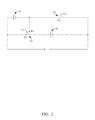
- FIG. 2 is a circuit diagram of one embodiment of the switch unit of FIG. 1 .
- FIG. 3 is a flow chart of a solar energy storing method, according to a second exemplary embodiment.
- FIG. 4 is a function block diagram of a solar energy storing system including a switch unit, according to a third exemplary embodiment.
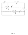
- FIG. 5 is a circuit diagram of one embodiment of the switch unit of FIG. 4 .
- the solar energy storing system 100 includes a solar energy converting unit 10 , a charging unit 20 , a switch unit 30 , a rechargeable battery unit 40 , a detecting unit 50 and a controlling unit 60 .
- the rechargeable battery unit 40 includes two rechargeable batteries 41 , 42 in the illustrated embodiment.
- the solar energy converting unit 10 is configured for converting solar energy into electrical energy to generate a charging voltage.
- the solar energy converting unit 10 may include a plurality of solar cells, such as solar cells made from monocrystalline silicon wafers.
- the charging unit 20 is configured for charging the rechargeable battery unit 40 using the charging voltage.
- the charging unit 20 may include many available charging circuits and/or chips to achieve the charging function. In other alternative embodiments, the charging unit 20 may be integrated with the rechargeable battery unit 40 .
- the switch unit 30 is configured for changing electrical connections between two rechargeable batteries 41 , 42 in the rechargeable battery unit 40 .
- the rechargeable batteries 41 , 42 connected in series may be changed by the switch unit 30 to be connected in parallel, or the rechargeable batteries 41 , 42 connected in parallel may be changed by the switch unit 30 to be connected in series.
- the rechargeable battery unit 40 is configured for storing the electrical energy converted by the solar energy converting unit 10 .
- the detecting unit 50 is configured for detecting the charging voltage of the solar energy converting unit 10 and a voltage of each of rechargeable batteries 41 , 42 in the rechargeable battery unit 40 , and determining a charging status between the charging voltage and the voltages of the rechargeable batteries 41 , 42 .
- the controlling unit 60 is configured for controlling the switch unit 30 to change the electrical connections between the rechargeable batteries 41 , 42 according to the charging status between the charging voltage and the voltages of the rechargeable batteries 41 , 42 . As mentioned above, changing the electrical connections may result in the rechargeable batteries 41 , 42 being connected in series or parallel.
- the switch unit 30 includes a selection switch S 1 and a switch S 2 .
- the selection switch S 1 includes a first end K 1 , a second end K 2 and a first pole L 1 .
- the switch S 2 includes a third end K 3 and a second pole L 2 .
- the first end K 1 is connected to the anode of the rechargeable battery 41 .
- the second end K 2 is connected to the cathode of the rechargeable battery 41 .
- the first pole L 1 is connected to the anode of the rechargeable battery 42 .
- the third end K 3 is connected to the cathode of the rechargeable battery 41 .
- the second pole L 2 is connected to the cathode of the rechargeable battery 42 .
- the detecting unit 50 detects two voltages V 1 , V 2 of the rechargeable batteries 41 , 42 and the charging voltage V generated by the solar energy converting unit 10 and determines the charging status between the charging voltage V and the voltages V 1 , V 2 .
- the controlling unit 60 controls the first pole L 1 to contact the second end K 2 and controls the switch S 2 to open. Therefore, the two rechargeable batteries 41 , 42 are connected in series, and the rechargeable battery unit 40 is charged by the charging voltage V.
- V ⁇ (V 1 +V 2 ), V>V 1 , V>V 2 and V 1 is about equal to V 2 , the controlling unit 60 controls the first pole L 1 to contact the first end K 1 and controls the second pole L 2 to contact the third end K 3 . Therefore, the two rechargeable batteries 41 , 42 are connected in parallel and the rechargeable battery unit 40 is charged by charging voltage V.
- the solar energy storing system 100 can charge the rechargeable battery unit 40 even when the charging voltage generated by the solar energy converting unit 10 is less than sum of voltages of each of rechargeable batteries 41 , 42 of the rechargeable battery unit 40 . Therefore, the solar energy storing system 100 can enhance utilization ratio of the solar energy.
- a solar energy storing method includes steps S 601 to S 604 .
- S 601 converting solar energy into electrical energy to generate a charging voltage.
- S 602 detecting a voltage of each of two rechargeable batteries 41 , 42 in the rechargeable battery unit 40 and determining a charging status between the charging voltage and the voltages of the two rechargeable batteries 41 , 42 .
- S 603 changing an electrical connection of the two rechargeable batteries 41 , 42 according to the charging status between the charging voltage and the voltages of the two rechargeable batteries 41 , 42 .
- S 604 charging the rechargeable battery unit 40 using the charging voltage.
- the solar energy storing method can be carried out by the solar energy storing system 100 .
- a solar energy storing system 200 is shown. Differences between the solar energy storing system 200 and the solar energy storing system 100 of the first exemplary embodiment are that the switch unit 80 and the rechargeable battery unit 90 are different.
- the rechargeable battery unit 90 includes three rechargeable batteries 91 , 92 , 93 . Further referring to FIG. 5 , the switch unit 80 includes a first selection switch S 3 , a second selection switch S 4 , a first switch S 5 and a second switch S 6 .
- the first selection switch S 3 includes a first end K 4 , a second end K 5 and a first pole L 3 .
- the second selection switch S 4 includes a third end K 6 , a fourth end K 7 and a second pole L 4 .
- the first switch S 5 includes a fifth end K 8 and a third pole L 5 .
- the second switch S 6 includes a sixth end K 9 and a fourth pole L 6 .
- the first end K 4 is connected to the anode of the rechargeable battery 91 .
- the second end K 5 is connected to the cathode of the rechargeable battery 91 .
- the first pole L 3 is connected to the anode of the rechargeable battery 92 .
- the third end K 6 is connected to the anode of the rechargeable battery 91 .
- the fourth end K 7 is connected to the cathode of the rechargeable battery 92 .
- the second pole L 4 is connected to the anode of the rechargeable battery 93 .
- the fifth end K 8 is connected to the cathode of the rechargeable battery 91 .
- the third pole L 5 is connected to the cathode of the rechargeable battery 92 .
- the sixth end K 9 is connected to the cathode of the rechargeable battery 93 .
- the fourth pole L 6 is connected to the cathode of the rechargeable battery 92 .
- the controlling unit 120 controls the first pole L 3 to contact the second end K 5 , and controls the second pole L 4 to contact the fourth end K 7 , and controls the first switch S 5 and the second switch S 6 to open, where V represents as the charging voltage generated by the solar energy converting unit 70 , V 1 represents as the voltage of the rechargeable battery 91 , V 2 represents as the voltage of the rechargeable battery 92 , and V 3 represents as the voltage of the rechargeable battery 93 .
- V represents as the charging voltage generated by the solar energy converting unit 70
- V 1 represents as the voltage of the rechargeable battery 91
- V 2 represents as the voltage of the rechargeable battery 92
- V 3 represents as the voltage of the rechargeable battery 93 .
- the three rechargeable batteries 91 , 92 , 93 are connected in series.
- V ⁇ (V 1 +V 2 +V 3 ), V>V 1 , V>V 2 , V>V 3 and V 1 is about equal to V 2 and V 2 is about equal to V 3
- the controlling unit 120 controls the first pole L 3 to contact the first end K 4 , and controls the second pole L 4 to contact the third end K 6 and controls the third pole L 5 to contact the fifth end K 8 and controls the fourth pole L 6 to contact the sixth end K 9 .
- the three rechargeable batteries 91 , 92 , 93 are connected in parallel.
- the rechargeable battery unit can include more than three rechargeable batteries.
Landscapes
- Engineering & Computer Science (AREA)
- Chemical & Material Sciences (AREA)
- Chemical Kinetics & Catalysis (AREA)
- Electrochemistry (AREA)
- General Chemical & Material Sciences (AREA)
- Life Sciences & Earth Sciences (AREA)
- Sustainable Development (AREA)
- Sustainable Energy (AREA)
- Manufacturing & Machinery (AREA)
- Power Engineering (AREA)
- Charge And Discharge Circuits For Batteries Or The Like (AREA)
- Secondary Cells (AREA)
Abstract
Description
Claims (8)
Applications Claiming Priority (3)
| Application Number | Priority Date | Filing Date | Title |
|---|---|---|---|
| CN200910302001 | 2009-04-30 | ||
| CN2009103020010A CN101877494B (en) | 2009-04-30 | 2009-04-30 | Solar energy storage system and method |
| CN200910302001.0 | 2009-04-30 |
Publications (2)
| Publication Number | Publication Date |
|---|---|
| US20100277115A1 US20100277115A1 (en) | 2010-11-04 |
| US8248021B2 true US8248021B2 (en) | 2012-08-21 |
Family
ID=43019980
Family Applications (1)
| Application Number | Title | Priority Date | Filing Date |
|---|---|---|---|
| US12/576,338 Expired - Fee Related US8248021B2 (en) | 2009-04-30 | 2009-10-09 | Solar energy storing system and method with changeable electrical connections between rechargeable batteries |
Country Status (2)
| Country | Link |
|---|---|
| US (1) | US8248021B2 (en) |
| CN (1) | CN101877494B (en) |
Cited By (1)
| Publication number | Priority date | Publication date | Assignee | Title |
|---|---|---|---|---|
| US20170301963A1 (en) * | 2014-08-22 | 2017-10-19 | Pathion Inc. | Method and apparatus for performing string-level dynamic reconfiguration in an energy system |
Families Citing this family (18)
| Publication number | Priority date | Publication date | Assignee | Title |
|---|---|---|---|---|
| US9721715B2 (en) * | 2009-01-22 | 2017-08-01 | 2Sentient Inc. | Solid state components having an air core |
| US8633671B2 (en) * | 2011-03-31 | 2014-01-21 | GM Global Technology Operations LLC | Photo-voltaic charging of high voltage traction batteries |
| CN102545301A (en) * | 2011-05-30 | 2012-07-04 | 上海华篷防爆科技有限公司 | Skid-mounted electric vehicle charging station |
| CN102545300A (en) * | 2011-05-30 | 2012-07-04 | 上海华篷防爆科技有限公司 | Sledging-installing type multifunctional energy charging station |
| JP2013066329A (en) | 2011-09-20 | 2013-04-11 | Sony Corp | SECONDARY BATTERY CHARGING DEVICE, CHARGING METHOD IN SECONDARY BATTERY CHARGING DEVICE, SOLAR CELL POWER GENERATOR, AND POWER GENERATION METHOD IN SOLAR CELL POWER GENERATOR |
| CN102568343A (en) * | 2011-12-26 | 2012-07-11 | 浙江万向太阳能有限公司 | Solar photovoltaic advertising system |
| CN103094961A (en) * | 2013-01-08 | 2013-05-08 | 厦门炜迪电子科技有限公司 | Solar dim-light recycling and storage system |
| CN103607023A (en) * | 2013-12-04 | 2014-02-26 | 青岛锐晶光电科技有限公司 | Charge control method for photovoltaic power generation system |
| CN104752779B (en) | 2013-12-25 | 2017-04-26 | 华为技术有限公司 | Battery device and electronic equipment |
| CN105529810A (en) * | 2016-01-17 | 2016-04-27 | 国家电网公司 | Photovoltaic charging system of energy-storage photovoltaic power station and control method thereof |
| CN105790413A (en) * | 2016-04-13 | 2016-07-20 | 江苏峰谷源储能技术研究院有限公司 | Cooling-type 10KVA domestic energy storage power system |
| CN105790414A (en) * | 2016-04-13 | 2016-07-20 | 江苏峰谷源储能技术研究院有限公司 | 10KVA domestic energy storage power supply system |
| CN105790417B (en) * | 2016-05-10 | 2019-02-01 | 云南省交通规划设计研究院 | Intelligent power management system and transmitting apparatus is adopted with data using the field of the system |
| CN105739402B (en) * | 2016-05-10 | 2018-10-26 | 云南省交通规划设计研究院 | A kind of field adopts transmitting apparatus with intelligent data and adopts forwarding method |
| US11205994B2 (en) * | 2017-05-09 | 2021-12-21 | Churaeconet Llc | Solar photovoltaic installation |
| JP7073669B2 (en) * | 2017-10-27 | 2022-05-24 | 株式会社デンソー | Power storage system |
| CN111146837A (en) * | 2019-12-31 | 2020-05-12 | Oppo广东移动通信有限公司 | Charging method and device, electronic device, storage medium |
| US12451700B2 (en) * | 2021-06-02 | 2025-10-21 | Yui Lung Tong | Stored-energy power systems |
Citations (4)
| Publication number | Priority date | Publication date | Assignee | Title |
|---|---|---|---|---|
| US20020146617A1 (en) * | 2001-04-06 | 2002-10-10 | The Boeing Company | Procedure for performing battery reconditioning on a space vehicle designed with one battery |
| US20090015191A1 (en) * | 2005-12-02 | 2009-01-15 | Benckenstein Jr Claude Leonard | Solar Panel With Pulse Charger |
| US20090072781A1 (en) * | 2007-09-13 | 2009-03-19 | Hiroyuki Takahashi | Power supply device, scanner power supply device, and image forming apparatus |
| US20090079383A1 (en) * | 2007-09-26 | 2009-03-26 | Enphase Energy, Inc. | Method and apparatus for power conversion with maximum power point tracking and burst mode capability |
Family Cites Families (2)
| Publication number | Priority date | Publication date | Assignee | Title |
|---|---|---|---|---|
| KR20020025151A (en) * | 2002-03-08 | 2002-04-03 | 이세선 | Handsfree kit using solar cell |
| CN100403620C (en) * | 2006-11-30 | 2008-07-16 | 北京恒基伟业投资发展有限公司 | A method and device for using photovoltaic battery self-adapted serial and parallel charging |
-
2009
- 2009-04-30 CN CN2009103020010A patent/CN101877494B/en not_active Expired - Fee Related
- 2009-10-09 US US12/576,338 patent/US8248021B2/en not_active Expired - Fee Related
Patent Citations (4)
| Publication number | Priority date | Publication date | Assignee | Title |
|---|---|---|---|---|
| US20020146617A1 (en) * | 2001-04-06 | 2002-10-10 | The Boeing Company | Procedure for performing battery reconditioning on a space vehicle designed with one battery |
| US20090015191A1 (en) * | 2005-12-02 | 2009-01-15 | Benckenstein Jr Claude Leonard | Solar Panel With Pulse Charger |
| US20090072781A1 (en) * | 2007-09-13 | 2009-03-19 | Hiroyuki Takahashi | Power supply device, scanner power supply device, and image forming apparatus |
| US20090079383A1 (en) * | 2007-09-26 | 2009-03-26 | Enphase Energy, Inc. | Method and apparatus for power conversion with maximum power point tracking and burst mode capability |
Cited By (1)
| Publication number | Priority date | Publication date | Assignee | Title |
|---|---|---|---|---|
| US20170301963A1 (en) * | 2014-08-22 | 2017-10-19 | Pathion Inc. | Method and apparatus for performing string-level dynamic reconfiguration in an energy system |
Also Published As
| Publication number | Publication date |
|---|---|
| CN101877494A (en) | 2010-11-03 |
| CN101877494B (en) | 2013-11-06 |
| US20100277115A1 (en) | 2010-11-04 |
Similar Documents
| Publication | Publication Date | Title |
|---|---|---|
| US8248021B2 (en) | Solar energy storing system and method with changeable electrical connections between rechargeable batteries | |
| CN103797683B (en) | Charging apparatus for secondary cell, charging method, photovoltaic generator and photovoltaic charged secondary battery system | |
| CN104919676B (en) | Electrical storage device and startup method | |
| US9035496B2 (en) | Power control system and controlling method thereof | |
| Sandbaumhüter et al. | Compatibility study towards monolithic self-charging power unit based on all-solid thin-film solar module and battery | |
| WO2022033002A1 (en) | Photovoltaic power generation system | |
| CN105471076A (en) | Composite power supply device adopting solar cell and all-solid-state secondary cell | |
| US20110084645A1 (en) | Power supply device and driving method thereof | |
| CN102904325A (en) | Integrated charger of mobile terminal and method for charging mobile terminal | |
| CN101340471A (en) | Solar mobile phone based on display screen | |
| CN106160106B (en) | A kind of wearable device and design method based on solar cell for supplying power | |
| TWI656725B (en) | System of power generation | |
| CN201000360Y (en) | Solar electronic scales | |
| CN105932764A (en) | Photovoltaic energy storage system with charging control equipment and control method of photovoltaic energy storage system | |
| CN101119401A (en) | Portable coat and charging method of handset | |
| CN208062815U (en) | A kind of lithium battery circuit and device | |
| CN2762421Y (en) | Electronic device with multiple power supply sources | |
| CN206564485U (en) | A kind of battery electric power storage managing device for photovoltaic generating system | |
| KR200418642Y1 (en) | Charging device using cell | |
| CN201434992Y (en) | Photovoltaic energy charging and discharging control device | |
| CN223348628U (en) | Charging circuit and electronic device | |
| CN202111637U (en) | a solar cell | |
| CN201444497U (en) | Small solar energy storage battery pack | |
| CN101404416A (en) | Solar storage battery charge controller and its control method | |
| CN209045577U (en) | A kind of photovoltaic module |
Legal Events
| Date | Code | Title | Description |
|---|---|---|---|
| AS | Assignment |
Owner name: HON HAI PRECISION INDUSTRY CO., LTD., TAIWAN Free format text: ASSIGNMENT OF ASSIGNORS INTEREST;ASSIGNOR:LAI, CHIH-CHEN;REEL/FRAME:023350/0664 Effective date: 20090731 |
|
| STCF | Information on status: patent grant |
Free format text: PATENTED CASE |
|
| FPAY | Fee payment |
Year of fee payment: 4 |
|
| FEPP | Fee payment procedure |
Free format text: MAINTENANCE FEE REMINDER MAILED (ORIGINAL EVENT CODE: REM.); ENTITY STATUS OF PATENT OWNER: LARGE ENTITY |
|
| LAPS | Lapse for failure to pay maintenance fees |
Free format text: PATENT EXPIRED FOR FAILURE TO PAY MAINTENANCE FEES (ORIGINAL EVENT CODE: EXP.); ENTITY STATUS OF PATENT OWNER: LARGE ENTITY |
|
| STCH | Information on status: patent discontinuation |
Free format text: PATENT EXPIRED DUE TO NONPAYMENT OF MAINTENANCE FEES UNDER 37 CFR 1.362 |
|
| FP | Lapsed due to failure to pay maintenance fee |
Effective date: 20200821 |