US8234978B1 - Hand-held firing device - Google Patents
Hand-held firing device Download PDFInfo
- Publication number
- US8234978B1 US8234978B1 US12/983,115 US98311510A US8234978B1 US 8234978 B1 US8234978 B1 US 8234978B1 US 98311510 A US98311510 A US 98311510A US 8234978 B1 US8234978 B1 US 8234978B1
- Authority
- US
- United States
- Prior art keywords
- firing
- firing pin
- trigger
- cylinders
- hollow cylinder
- Prior art date
- Legal status (The legal status is an assumption and is not a legal conclusion. Google has not performed a legal analysis and makes no representation as to the accuracy of the status listed.)
- Expired - Fee Related
Links
Images


Classifications
-
- F—MECHANICAL ENGINEERING; LIGHTING; HEATING; WEAPONS; BLASTING
- F41—WEAPONS
- F41A—FUNCTIONAL FEATURES OR DETAILS COMMON TO BOTH SMALLARMS AND ORDNANCE, e.g. CANNONS; MOUNTINGS FOR SMALLARMS OR ORDNANCE
- F41A19/00—Firing or trigger mechanisms; Cocking mechanisms
- F41A19/06—Mechanical firing mechanisms, e.g. counterrecoil firing, recoil actuated firing mechanisms
- F41A19/07—Mechanical firing mechanisms, e.g. counterrecoil firing, recoil actuated firing mechanisms press-button actuated, e.g. with thumb rest
-
- F—MECHANICAL ENGINEERING; LIGHTING; HEATING; WEAPONS; BLASTING
- F41—WEAPONS
- F41C—SMALLARMS, e.g. PISTOLS, RIFLES; ACCESSORIES THEREFOR
- F41C3/00—Pistols, e.g. revolvers
- F41C3/02—Signal pistols, e.g. Very pistols
-
- F—MECHANICAL ENGINEERING; LIGHTING; HEATING; WEAPONS; BLASTING
- F42—AMMUNITION; BLASTING
- F42D—BLASTING
- F42D1/00—Blasting methods or apparatus, e.g. loading or tamping
- F42D1/04—Arrangements for ignition
Definitions
- the present invention relates generally to devices for initiating detonation of a non-electric detonator.
- Non-electric detonators may be used to initiate detonation of larger explosives, such as, for example, a shaped charge or explosives used to create an opening in a building's wall or a gate.
- Hand held firing devices are known to include a firing pin or other sharp object to strike non-electric detonators to cause ignition thereof.
- the non-electric detonator may be created so that the firing pin must strike the detonator in a specific location and with a specific force, in order to prevent inadvertent or unintentional detonation.
- a user may desire a safe and reliable way of triggering a non-electric detonator, so that the requirements to detonate the non-electric detonator are met in a reliable and reproducible manner.
- a firing device apparatus in an exemplary embodiment of the present disclosure, includes a first hollow cylinder.
- the apparatus further includes a second hollow cylinder laterally spaced from, and extending substantially parallel to, the first hollow cylinder, each of the first and second hollow cylinders having a longitudinal axis, an inner surface and an outer surface, and extending longitudinally between a first end and a second end.
- the apparatus further includes a spring disposed in each of the first and second hollow cylinders.
- the apparatus further includes a firing pin disposed in each of the first and second hollow cylinders, wherein each spring is positioned between the first end of one of the first and second cylinders and the respective firing pin.
- the apparatus further includes a lever structure having a portion extending substantially perpendicular to the longitudinal axis of the first and second hollow cylinders, and coupled to the firing pins disposed in each of the first and second hollow cylinders through openings in the first and second hollow cylinders.
- the lever structure is positioned outside of the first and second hollow cylinders and is configured to move longitudinally in response to movement of the firing pins.
- a first bushing is disposed between the first portion of the lever structure and the first hollow cylinder, the first bushing being interposed within the opening of the first hollow cylinder.
- a second bushing is disposed between the first portion of the lever structure and the second hollow cylinder, the second bushing being interposed within the opening of the second hollow cylinder.
- a method for initiating a detonator includes coupling a detonator to a hollow cylinder of a firing device, adjusting a stop lock screw to define a set point for a firing pin supported for sliding movement within the hollow cylinder, providing a sear lever external to the cylinder and supported for movement with the firing pin, providing a trigger to secure the sear lever in a firing position, activating the trigger to release the sear lever and causing a spring to move the firing pin into contact with the detonator, and insulating the sear lever from the cylinder during movement therebetween.
- FIG. 1 is a top view of a firing device according to an embodiment of the present disclosure
- FIG. 2 is a side view of the firing device according to an embodiment of the present disclosure shown in FIG. 1 ;
- FIG. 3A is a rear perspective view of the firing device according to an embodiment of the present disclosure shown in FIG. 1 ;
- FIG. 3B is a front perspective view of the firing device according to an embodiment of the present disclosure shown in FIG. 1 ;
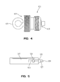
- FIG. 4 is a top view of a threaded cap according to an embodiment of the present disclosure.
- FIG. 5 is a top view of a firing pin according to an embodiment of the present disclosure.
- FIG. 6A is a side view of a sear lever according to an embodiment of the present disclosure.
- FIG. 6B is a front view of the sear lever of FIG. 6A according to an embodiment of the present disclosure
- FIG. 6C is a top view of the sear lever of FIG. 6A according to an embodiment of the present disclosure.
- FIG. 7 is a top view of a trigger safety cylinder according to an embodiment of the present disclosure.
- FIG. 8 is a top view of a trigger safety selector and trigger safety cylinder according to an embodiment of the present disclosure.
- FIG. 9 is an exploded view of the firing device shown in FIG. 1 according to an embodiment of the present disclosure.
- firing device 100 is configured to receive at least one non-electric detonator 194 for initiation thereof.
- the non-electric detonator 194 is in communication with a fuse, illustratively a non-electric detonator cord (not shown).
- the detonator cord may comprise a tube with an explosive core and is configured to detonate a main explosive charge (not shown).
- the firing device 100 may include a body 102 having first and second hollow cylinders 101 A, 101 B laterally spaced and extending in a longitudinal direction.
- a threaded cap 103 , a spring 192 , a firing pin 125 , and a firing pin stop lock screw 131 are associated with each of the cylinders 101 A, 101 B.
- a laterally extending lever structure or sear lever 117 is operably coupled to the firing pins 125 of each cylinder 101 A, 101 B.
- a trigger 109 may pivot within a trigger attachment bracket 157 , and may catch and release the sear lever 117 from a firing (retracted) position to a fired (extended) position.
- a trigger safety 143 and a secondary safety 135 may be used to prevent accidental release of the sear lever 117 (i.e., provide alternate safe and firing modes when the sear lever is in the firing position).
- the cylinders 101 A, 101 B may be metal, for example an aluminum or aluminum alloy, and may be attached together or may be milled from a single block of metal defining body 102 . While FIG. 1 shows two cylinders 101 A, 101 B, embodiments may include one cylinder, or more than two cylinders 101 A, 101 B attached together or milled from a single block of material.
- the cylinders 101 A, 101 B may be hollow, and may be joined together via a bridge 155 or other connecting surface.
- the bridge 155 may be milled with the cylinders 101 A, 101 B, or the cylinders 101 A, 101 B may be joined to the bridge 155 .
- the cylinders 101 A, 101 B may include a first end 190 and a second end 191 , and the first end 190 and the second end 191 may be open.
- the first end 190 and the second end 191 may include threads 350 disposed along the inner surface 360 of the cylinder walls, and the inner surface 360 of the cylinder walls may otherwise be unthreaded.
- the cylinders 101 A, 101 B may also include one or more indentations or recesses 195 on the outer surface of the cylinders 101 A, 101 B.
- the indentations 195 may allow for the seating of one or more non-electric detonators.
- the non-electric detonators may have one or more projections that seat within the indentations 195 , or the non-electric detonators may be sized so that the indentations 195 are necessary so that the firing pin 125 may strike the non-electric detonator.
- the cylinders 101 A, 101 B may be of a thickness to allow the cylinders 101 A, 101 B to be durable against use and/or wear.
- the cylinders 101 A, 101 B may be sized so that they are able to withstand repeated forces from inserting and/or removing detonators, or from forces sustained during the initiation of one or more detonators.
- the cylinders 101 A, 101 B may also include a flat portion 150 that may provide a cooperating surface for the sear lever 117 and/or bushings 121 .
- the inner and/or outer surface of the cylinders 101 A, 101 B may be coated with a material, or anodized, or may be treated with another chemical or mechanical process to alter its properties.
- the outer surface may be anodized to create a substantially unreflective matte surface or to strengthen wear resistance, or the outer surface may be painted.
- the inner surface and/or the outer surface may also be treated to alter its properties.
- the inner surface may be anodized, painted, or polished, or a layer of oil, a fluoropolymer such as Teflon®, or other substance may be applied to protect the inner surface from corrosion, to reduce wear, or to increase reliability.
- each of the cylinders 101 A, 101 B also includes a sear lever opening 123 , a stop lock screw opening 133 , and two secondary safety openings 180 .
- the sear lever opening 123 and the stop lock screw opening 133 are openings in the cylinders 101 A, 101 B from the outer surface to the inner surface.
- the sear lever opening 123 allows for the connection between a sear lever 117 and a firing pin 125 , and also for the movement of the sear lever 117 and firing pin 125 within the cylinder, described more fully below.
- the stop lock screw opening 133 allows for the installation of a stop lock screw 131 , described more fully below.
- the secondary safety openings 180 are positioned between the firing pin stop lock screw openings 133 and the sear lever openings 123 , and are arranged along an axis that is perpendicular to the longitudinal axis of the cylinder.
- the secondary safety openings for each of the cylinders 101 A, 101 B are arranged along a single perpendicular axis to the cylindrical axes of the cylinders 101 A, 101 B.
- the threaded cap 103 is attached to the first end 190 of each of the cylinders 101 A, 101 B.
- the threaded cap 103 may be stamped or milled, and may be aluminum or another metal, and are installed within the cylinders 101 A, 101 B so that the springs 192 rest against a fixed object.
- the threaded cap 103 may include threads along the outer surface that are comparable to the threads disposed along the inner surface of the first end 190 of the cylinders 101 A, 101 B, and may engage with the cylinder inner surface threads to releasably engage the threaded cap 103 with the first end 190 of the cylinders 101 A, 101 B.
- the first end 401 of the threaded cap 103 may include projections or indentations to facilitate turning the threaded cap 103 to engage with the first end 190 of the cylinders 101 A, 101 B.
- the threaded cap 103 may be cylindrical, and may be closed on the first end 401 . In an embodiment, the threaded cap 103 may also be closed on the second end 403 .
- One or more of the threaded caps 103 engaged with the cylinders 101 A, 101 B may also include an eye hook 105 .
- the eye hook 105 may be affixed to the first closed end 401 of one or more of the threaded caps 103 , or may be releasably attached to the threaded cap 103 by, for example and without limitation, threads that may engage threads formed within a void through the first end 401 of the threaded cap 103 .
- the first end 401 of the cylinder is closed, and a threaded cap 103 is not provided.
- Springs 192 may be a metal, for example steel or steel alloy, and are disposed within each of the cylinders 101 A, 101 B, so that the springs 192 may rest against the inner surface of the first end 401 of the threaded cap 103 that is engaged with the first end 190 of the cylinder. In an embodiment, if the second end 403 of the threaded cap 103 is closed, the spring 192 disposed within the cylinder may rest against the outer surface of the second end 403 of the threaded cap 103 .
- the springs 192 may be compressible along the cylindrical axis of each of the cylinders 101 A, 101 B.
- the springs 192 in the illustrative embodiment, are closed springs and may be compressed so that each spring 192 pushes its associated firing pin 125 to strike a non-electric detonator with at least 675 pounds of force.
- firing pins 125 may be a metal, for example steel or steel alloy, and are disposed within each of the cylinders 101 A, 101 B, so that within each of the cylinders 101 A, 101 B, the spring 192 is between the firing pin 125 and the threaded cap 103 .
- Each firing pin 125 may include a spring end 501 , which may be circular.
- the spring end 501 may have a diameter that is slightly smaller than the inner diameter of the cylinders 101 A, 101 B, so that the firing pin 125 may move along the cylindrical or longitudinal axis of the cylinders 101 A, 101 B, but may not rotate in an axis that is perpendicular to the cylindrical axis of the cylinders 101 A, 101 B.
- the pin end 129 of the firing pin 125 may be a different metal than the spring end 501 , and the pin end 129 and the spring end 501 may be joined together by, for example and without limitation, welding or other bonding, or the pin end 129 and the spring end 501 may be the same material.
- the pin end 129 may taper 127 to a point as the pin end 129 extends in the direction of the second end 191 of the cylinders 101 A, 101 B.
- the spring end 501 of the firing pin 125 may be affixed to the spring 192 , or the spring end 501 may not be affixed to the spring 192 , so that the firing pin 125 rides along the cylindrical axis of the cylinders 101 A, 101 B.
- the firing pins 125 may also include a flat portion 503 to engage or seat the bushings 121 .
- Firing pin stop locks 132 may be a metal, such as stainless steel.
- the firing pin stop locks 132 may be substantially cylindrical and may be threaded on the outer surface. The threads of the outer surface of the firing pin stop locks 132 may engage with the threads on the inner surface of the cylinders 101 A, 101 B, so that rotation of the firing pin stop locks 132 within the cylinders 101 A, 101 B moves the firing pin stop locks 132 along the longitudinal axis of the cylinders 101 A, 101 B.
- the firing pin stop locks 132 may be hollow, so that the pin end 129 of the firing pins 125 may extend through the firing pin stop locks 132 , but the firing pins 125 may be constrained from further forward movement along the cylindrical axis of the cylinders 101 A, 101 B by the firing pin stop locks 132 .
- the depth that the firing pins 125 are allowed to extend in the cylinders 101 A, 101 B may be controlled by the positioning of the firing pin stop locks 132 within the cylinders 101 A, 101 B.
- the firing pin stop locks 132 establish a detonator set point or limit stop for the travel of the firing pin 125 axially within the cylinder 101 A, 101 B.
- the firing pin stop locks 132 may be adjustable so that the firing pin 125 effectively contacts and initiates detonators of differing sizes, as shown more fully below.
- Firing pin stop lock screws 131 may be a metal, such as stainless steel.
- the firing pin stop lock screw 131 may be substantially cylindrical and may include threads disposed on the outer surface. The threads of the firing pin stop lock screw 131 may engage with threads disposed on the inner surface of the firing pin stop lock screw opening 133 on the cylinders 101 A, 101 B, so that the firing pin stop lock screw 131 may be engaged with the cylinders 101 A, 101 B.
- the firing pin stop lock screw 131 may extend into the cylinders 101 A, 101 B, and the depth of extension of the firing pin stop lock screw 131 into the cylinders 101 A, 101 B may be adjusted by rotating the firing pin stop lock screw 131 .
- the firing pin stop lock screw 131 may be adjusted so that the end of the firing pin stop lock screw 131 that extends into the cylinders 101 A, 101 B may contact the firing pin stop lock 132 , and may limit rotation of the firing pin stop lock 132 within the cylinders 101 A, 101 B.
- the sear lever 117 may be positioned over the cylinders 101 A, 101 B.
- the sear lever 117 may be a metal, for example stainless steel, and may be positioned above the sear lever openings 123 of the cylinders 101 A, 101 B.
- the sear lever 117 may be positioned so that bushings 121 are located between the sear lever 117 and the cylinders 101 A, 101 B.
- a base 134 of the sear lever 117 extends substantially parallel to the longitudinal axes of the cylinders 101 A, 101 B and supports a pair of upwardly extending tabs 136 .
- the tabs 136 extend substantially perpendicular to the longitudinal axes of the cylinders 101 A, 101 B and may be engaged by an operator's fingers when resetting the firing pins 125 as further detailed herein.
- the bushings 121 may be a softer metal than the sear lever 117 and/or the cylinder or may be another material that is softer than the sear lever 117 and/or the cylinder, to prevent the sear lever 117 from being in direct contact with the cylinder.
- the bushings 121 may be in contact with a flat portion 503 of the firing pins 125 , shown in FIG. 5 .
- the bushings 121 may be stainless steel.
- the bushings 121 may be molded from a polymer, such as a nylon or one or more fluoropolymer compounds. As shown in FIG.
- the bushings 121 may illustratively include a first portion 913 and a second portion 915 , with a flange portion 917 separating the first portion 913 from the second portion 915 .
- the first portion 913 may extend through the sear lever opening 123 and abut the flat portion 503 of the firing pins 125 .
- the second portion 915 may extend through the voids 601 of the sear lever 117 and abut the washers 120 or the screws 119 .
- the flange portion 917 may separate the sear lever 117 from the cylinders 101 A, 101 B, and may abut the flat portion 150 of the cylinders 101 A, 101 B.
- an oil, graphite, or other liquid or solid lubricant may be applied between the sear lever 117 and the cylinders 101 A, 101 B, or between the bushings 121 and the cylinders 101 A, 101 B, to reduce wear, decrease friction, or increase resistance or longevity.
- the second portion 915 of the bushings 121 may contact an inner surface of the sear lever opening 123 , and a similar liquid or solid lubricant may also be applied between the second portion 915 of the bushings 121 and the sear lever opening 123 .
- the bushings 121 may be a wearable component, and so the bushings 121 may wear and be replaced prior to the sear lever 117 and/or cylinders 101 A, 101 B.
- the sear lever 117 may include one or more voids 601 from the top surface 603 of the sear lever 117 to the bottom surface 605 of the sear lever 117 in contact with the bushings 121 .
- one void 601 is associated with each sear lever opening 123 .
- Firing pin couplers 119 illustratively screws or other fasteners, extend from the top surface 603 of the sear lever 117 , through the sear lever 117 to the bottom surface 605 of the sear lever 117 , through the bushings 121 , and through the sear lever opening 123 .
- the screws 119 may be offset from the sear lever 117 by one or more washers 120 .
- Each screw 119 is illustratively received within a threaded hole 126 or other attachment point on the firing pin 125 .
- the screw 119 or other fastener may thus couple the sear lever 117 to the firing pin 125 .
- the sear lever 117 may be fastened to the firing pin 125 through the use of a rivet, or the sear lever 117 may include a projection that extends through the bushings 121 , through the sear lever opening 123 in the cylinder, and that is in communication with the firing pin 125 by, for example and without limitation, welding.
- the firing pins 125 are configured to move axially and concurrently with the sear lever 117 .
- the sear lever 117 is attached to the firing pins 125 in both cylinders 101 A, 101 B. In an embodiment with more or fewer cylinders 101 A, 101 B, the sear lever 117 may be attached to more or fewer of the respective firing pins 125 .
- a trigger support or bracket 157 may be fixed to the bridge 155 and positioned laterally between the cylinders 101 A, 101 B.
- the trigger attachment bracket 157 may be formed of a metal such as, for example and without limitation, aluminum or an aluminum alloy.
- the trigger attachment bracket 157 may include a groove extending between the longitudinal axes of the cylinders 101 A, 101 B.
- the trigger attachment bracket 157 may include a void 144 for a trigger safety 143 , described below, and a void 148 for the trigger 109 , described below, that extend through the trigger attachment bracket 157 along an axis that is perpendicular to the longitudinal axes of the cylinders 101 A, 101 B.
- the trigger 109 may be a metal such as, for example and without limitation, aluminum or an aluminum alloy.
- the trigger 109 illustratively includes a release portion 198 and a catch portion 197 positioned on opposing sides of a pivot. More particularly, the trigger 109 may include one or more pins 196 that extend through the trigger void 148 in the trigger attachment bracket 157 and held in place by one or more clips 156 or other retaining structures, creating a pivot for the trigger 109 between an open position, when the release portion of the trigger 109 is positioned relatively closer to the trigger attachment bracket 157 , and a closed position, when the release portion 198 of the trigger 109 is positioned relatively farther away from the trigger attachment bracket 157 .
- the catch portion 197 of the trigger 109 is positioned relatively farther away from the trigger attachment bracket 157 (and the sear lever 117 ) in the open position, and is positioned relatively closer to the trigger attachment bracket 157 (and the sear lever 117 ) in the closed position.
- a trigger spring 111 is positioned between the trigger attachment bracket 157 and the trigger release portion 198 , biasing the trigger release portion 198 away from the trigger attachment bracket 157 and toward the closed position.
- a trigger spring stop 112 may be within the spring and may be fixed to the trigger 109 , preventing the trigger release portion 198 from striking the bridge 155 .
- the catch portion 197 of the trigger 109 rests closer to the bridge 155 than the top of the sear lever 117 , retaining the sear lever 117 toward the first end 190 of the cylinder against the bias of the spring 192 . If the trigger 109 is in an open position, the catch portion 197 of the trigger 109 is farther away from the bridge 155 than the sear lever 117 base, allowing the sear lever 117 and firing pins 125 to travel freely along the longitudinal axis of the cylinder, subject to the bias of the springs 192 (and if trigger safety 143 is in a firing position).
- the trigger safety 143 may be a metal, and may include a trigger safety selector 149 and a trigger safety cylinder 145 .
- the trigger safety selector 149 and the trigger safety cylinder 145 may be machined or stamped from a single piece of metal, or may be two or more parts that are attached together.
- the trigger safety selector 149 has a flat shape and is rotatable between a first (safe) position and a second (firing) position.
- the side of the trigger safety selector 149 showing to the user in the first (safe) position may have a different texture than the side of the selector showing to the user in the second (firing) position, in addition to having one or more other markings to indicate whether the trigger safety selector 149 is in the first position or the second position.
- the trigger safety selector 149 may be rotatable while the trigger 109 is in the closed position.
- the trigger safety cylinder 145 may extend through a void 144 in the trigger attachment bracket 157 , may be secured with one or more clips 146 or other retaining structure, and may be closer to the bridge 155 than the trigger 109 .
- the trigger safety cylinder 145 may include one or more projections or indentations 701 that selectively interact with the trigger 109 . If the trigger safety selector 149 is in the first position, the trigger safety cylinder 145 is rotationally positioned within the trigger attachment bracket 157 such that the trigger 109 contacts the trigger safety cylinder 145 before the trigger 109 pivots sufficiently such that the sear lever 117 has enough clearance under the catch portion 197 of the trigger 109 to move toward the second end 191 of the cylinder (i.e., the trigger 109 may not be able to be fully depressed).
- the trigger safety cylinder 145 is rotationally positioned within the trigger attachment bracket 157 such that the trigger 109 is received within the indentation 701 of the trigger safety cylinder 145 (i.e., the trigger 109 may be able to be fully depressed).
- the trigger safety cylinder 145 may thus present a mechanical stop to prevent the trigger 109 from being fully depressed such that the catch portion 197 restrains movement of the sear lever 117 and hence, firing pins 125 .
- the trigger safety cylinder 145 may prevent the trigger 109 from being fully depressed.
- the trigger safety cylinder 145 may also includes groove 703 in which is deposited an o-ring 903 , shown in FIG. 9 .
- the o-ring 903 may be an elastomeric compound or other deformable compound, and may be deposited into the groove 703 , which may be spaced within the void 144 , adding friction to the movement of the trigger safety cylinder 145 and the trigger safety selector 149 and preventing the trigger safety cylinder 145 and the trigger safety selector 149 from freely rotating within the void 144 .
- the secondary safety 135 may include a cylindrical pin 141 that extends through secondary safety openings 180 of the cylinders 101 A, 101 B, and a releasable detent 139 operably coupled to a button 137 that allows the cylindrical pin 141 to releasably positioned within the cylinders 101 A, 101 B.
- the detents 139 are illustratively spring biased and positioned on the outer surface of the pin 141 at an end opposite the button 137 , so that pressing the button 137 may retract the detents 139 into the cylindrical pin 141 , and releasing the button 137 may extend the detents 139 out of the cylindrical pin 141 .
- the cylindrical pin 141 with the projections 139 retracted may be narrower than the secondary safety openings 180 of the cylinders 101 A, 101 B, and the cylindrical pin 141 with the projections 139 extended may be larger than the secondary safety openings 180 of the cylinders 101 A, 101 B.
- the secondary safety openings 180 on the cylinders 101 A, 101 B are arranged so that the cylindrical pin 141 of the secondary safety 135 may extend through one of the secondary safety openings 180 , through the inner portion of the cylinder, out of the other secondary safety openings 180 for the cylinder, and through a secondary safety opening 180 for another cylinder, until the cylindrical pin 141 passes through each of the cylinders 101 A, 101 B and out of the last cylinder 101 B in the firing device 100 .
- the secondary safety openings 180 are arranged on the cylinders 101 A, 101 B so that, if the secondary safety 135 is installed, the firing pin 125 in the cylinders 101 A, 101 B will strike the cylindrical pin 141 of the secondary safety 135 before the firing pin 125 strikes the firing pin stop lock screw 131 .
- the secondary safety 135 may not be installed within the cylinders 101 A, 101 B unless the sear lever 117 is pulled toward the first end 190 of the cylinder 101 A, 101 B against the bias of the spring 192 , and is held by the catch portion 197 of the trigger 109 .
- the firing pins 125 do not rest against the secondary safety 135 when the sear lever 117 is in its firing (retracted) position but a gap is provided therebetween.
- a lanyard 107 may be attached to the eye hook 105 on one or more of the threaded caps 103 , and may also be attached to an attachment point on the secondary safety 135 .
- the lanyard 107 ensures that the secondary safety 135 continues to be attached to the firing device 100 , even if the secondary safety 135 is not disposed within the cylinders 101 A, 101 B.
- the lanyard 107 may be a metal wire or metal wires, for example a braided stainless steel wire, and may be coated with another material.
- the lanyard 107 may be coated with a plastic or rubber material, or the wire of the lanyard 107 may be chemically treated to improve wear resistance or to change other properties such as color or texture.
- the attachment of the lanyard 107 to the secondary safety 135 and the eye hook 105 may be fixed, or may be releasable, so that the secondary safety 135 may be detached from the firing device 100 .
- a catch 151 is supported below the cylinders' 101 A, 101 B proximate ends 191 .
- the catch 151 may include projections to allow for releasable attachment to a part of one or more detonators.
- the catch 151 may be removable, and may be attached to the cylinders 101 A, 101 B.
- the cylinders 101 A, 101 B may include projections or indentations that may engage with similar projections or indentations on the catch 151 .
- the catch 151 may be made from a metal such as aluminum or aluminum alloy, or may be made from steel or a steel alloy.
- the catch 151 may be attached to the cylinders 101 A, 101 B by screws 901 , shown in FIG. 9 , or other fasteners.
- the screws are cross-head and are countersunk into countersink areas (not shown) in the catch 151 .
- the screws 901 may be in communication with one or more voids (not shown) in the cylinders 101 A, 101 B to secure the catch 151 to the cylinders 101 A, 101 B.
- the firing device 100 may be positioned in a “safe” position, an “armed” position, and a “fired” position.
- the safe position i.e., firing (retracted) position
- the sear lever 117 is positioned towards the first end 190 of the cylinders 101 A, 101 B, and the top surface 603 of the sear lever 117 is engaged with the catch portion 197 of the trigger 109 , so that the catch portion 197 of the trigger 109 holds the sear lever 117 towards the first end 190 of the cylinders 101 A, 101 B, against the bias of the springs 192 in the cylinders 101 A, 101 B.
- the secondary safety 135 is inserted into the cylinders 101 A, 101 B, and the button 137 on the secondary safety 135 is not depressed, so that the projections 139 on the secondary safety cylindrical pin 141 are extended.
- the trigger safety 143 is illustratively in the first (safe) position, preventing the trigger 109 from being depressed.
- the secondary safety 135 In the armed position, the secondary safety 135 has been removed from the cylinders 101 A, 101 B by depressing the button 137 on the secondary safety 135 , thus retracting the projections 139 of the cylindrical pin 141 , and the secondary safety 135 has been removed.
- the secondary safety 135 may be attached to the firing device 100 by the lanyard 107 .
- the trigger safety 143 has been rotated to the second (firing) position.
- the trigger 109 In the fired position, the trigger 109 has been depressed, overcoming the bias from the trigger spring 111 .
- the sear lever 117 no longer held in place by the catch portion 197 of the trigger 109 , is biased toward the second end 191 of the cylinders 101 A, 101 B by the spring 192 , and the firing pins 125 in the cylinders 101 A, 101 B rest against the firing pin stop 132 .
- the tips 129 of the firing pins 125 extend through the firing pin stops 132 to strike the non-electric detonators 194 .
- the firing device 100 may begin at, for example, the armed position.
- a user inserts a non-electric detonator 194 within the second end 191 of the cylinder.
- the non-electric detonator 194 may be cylindrical, and the diameter of the non-electric detonator 194 may be smaller than the diameter of the inner surface of the cylinders 101 A, 101 B.
- the non-electric detonator 194 may include threads 199 disposed on the outer surface, so that the threads 199 of the non-electric detonator 194 may engage with the threads (not shown) disposed on the inner surface of the second end 191 of the cylinder, holding the non-electric detonator 194 in place.
- the non-electric detonator 194 may be held in place within the cylinder via, for example and without limitation, a friction fit, or a clip or other device disposed outside of the cylinders 101 A, 101 B to hold the non-electric detonator 194 in place within the cylinders 101 A, 101 B.
- the non-electric detonator 194 may be positioned within the cylinder so that the firing pin 125 may strike the non-electric detonator 194 , and the firing pin stop 132 may be adjusted to ensure contact between the firing pin 125 and the non-electric detonator 194 .
- the firing pin stop screws 131 are secured against the firing pin stops 132 to prevent rotation after adjustment of the firing pin stops 132 .
- the non-electric detonator 194 may be attached to or in communication with an amount of explosives via a fuse, such as detonator cord (not shown).
- the user may remove the secondary safety 135 by pressing the button 137 on the secondary safety 135 , retracting the projections 139 of the cylindrical pin 141 , and removing the secondary safety 135 from the cylinders 101 A, 101 B.
- the user may then rotate the trigger safety 143 from the first position to the second position, and may depress the trigger 109 , overcoming the bias of the trigger spring 111 .
- the trigger 109 may pivot within the trigger attachment bracket 157 , and the catch portion 197 of the trigger 109 no longer restricts the sear lever 117 .
- the sear lever 117 is biased by the springs 192 within the cylinders 101 A, 101 B to move the firing pin 125 towards the second end 191 of the cylinders 101 A, 101 B.
- the firing pins 125 and the sear lever 117 move toward the second end 191 of the cylinders 101 A, 101 B, and strikes the non-electric detonators 194 positioned therein.
- the non-electric detonator 194 may ignite, initiating detonation of the amount of explosives in communication with the non-electric detonator.
- the firing pins 125 may continue to travel in the direction of the second end 191 of the cylinders 101 A, 101 B, until the firing pins 125 strike the firing pin stop lock screws 131 and movement ceases, and the firing device 100 is in the fired position.
- the user may remove the non-electric detonators 194 from the firing device 100 .
- the user may then push the sear lever 117 towards the first end 190 of the cylinders 101 A, 101 B, overcoming the bias of the springs 192 within the cylinders 101 A, 101 B.
- Movement of the sear lever 117 may push the catch portion 197 of the trigger 109 away from the bridge 155 , overcoming the bias of the trigger spring 111 , so that the catch portion of the trigger 109 may ride along or above the upper surface 603 of the sear lever 117 , while the sear lever 117 is pulled towards the first end 190 of the cylinders 101 A, 101 B.
- the sear lever 117 When the sear lever 117 is closer to the first end 190 of the cylinders 101 A, 101 B than the catch portion of the trigger 109 , the bias of the trigger spring 111 pushes the catch portion toward the bridge 155 , holding the sear lever 117 in place.
- the user may then rotate the trigger safety 143 from the second position to the first position, and the user may press the button 137 of the secondary safety 135 , retracting the projections ( 139 ) on the cylindrical pin 141 .
- the user may then position the secondary safety 135 within the cylinders 101 A, 101 B, and may release the button 137 , extending the projections ( 139 ) on the cylindrical pin 141 and preventing the secondary safety 135 from being removed.
- the firing device 100 is then in the safe position as detailed above.
Landscapes
- Engineering & Computer Science (AREA)
- General Engineering & Computer Science (AREA)
- Automotive Seat Belt Assembly (AREA)
Abstract
Description
Claims (33)
Priority Applications (1)
| Application Number | Priority Date | Filing Date | Title |
|---|---|---|---|
| US12/983,115 US8234978B1 (en) | 2010-12-31 | 2010-12-31 | Hand-held firing device |
Applications Claiming Priority (1)
| Application Number | Priority Date | Filing Date | Title |
|---|---|---|---|
| US12/983,115 US8234978B1 (en) | 2010-12-31 | 2010-12-31 | Hand-held firing device |
Publications (1)
| Publication Number | Publication Date |
|---|---|
| US8234978B1 true US8234978B1 (en) | 2012-08-07 |
Family
ID=46583122
Family Applications (1)
| Application Number | Title | Priority Date | Filing Date |
|---|---|---|---|
| US12/983,115 Expired - Fee Related US8234978B1 (en) | 2010-12-31 | 2010-12-31 | Hand-held firing device |
Country Status (1)
| Country | Link |
|---|---|
| US (1) | US8234978B1 (en) |
Cited By (5)
| Publication number | Priority date | Publication date | Assignee | Title |
|---|---|---|---|---|
| US9021956B1 (en) * | 2013-05-03 | 2015-05-05 | The United States Of America As Represented By The Secretary Of The Navy | Mechanical firing adapter for a M81 device |
| WO2016183255A1 (en) * | 2015-05-12 | 2016-11-17 | Cgs Group, Llc | Firing device |
| US9816771B2 (en) * | 2013-11-18 | 2017-11-14 | Francesco GHITTI | Thumb-operable firearm |
| US9846019B1 (en) * | 2016-06-17 | 2017-12-19 | Rheinmetall Waffe Munition Arges Gmbh | Rocker arm detonator |
| CN117662965A (en) * | 2023-12-13 | 2024-03-08 | 湖南响箭氢能新能源有限公司 | A multi-layer wrapped hydrogen storage tank steel plate end alignment equipment |
Citations (11)
| Publication number | Priority date | Publication date | Assignee | Title |
|---|---|---|---|---|
| US1474377A (en) * | 1920-08-09 | 1923-11-20 | Us Government | Torpedo |
| US2757474A (en) * | 1954-02-26 | 1956-08-07 | Don C Williams | Pen type tear gas gun |
| US2947220A (en) * | 1958-01-23 | 1960-08-02 | Creston F Laager | Single trigger sequential firing mechanism |
| US3174246A (en) * | 1962-08-16 | 1965-03-23 | Currency Prot Inc | Robbery protective device with time delay means |
| US3214857A (en) * | 1963-10-10 | 1965-11-02 | Felix A Tyrone | Burglar alarm unit |
| US3641868A (en) * | 1970-07-14 | 1972-02-15 | Us Army | Firing mechanism for a multishot rocket launcher |
| US6272996B1 (en) | 1998-10-07 | 2001-08-14 | Shock Tube Systems, Inc. | In-line initiator and firing device assembly |
| US6581519B1 (en) * | 2001-10-11 | 2003-06-24 | Leslie K. Adams | Blasting cap initiator system |
| WO2003071220A2 (en) | 2002-02-15 | 2003-08-28 | Ensign-Bickford Aerospace & Defense Company | Initiation fixture and an initiator assembly including the same |
| US7069862B2 (en) | 2002-08-05 | 2006-07-04 | Carroll Bassett | Handheld tool for breaking up rock |
| US7708178B2 (en) | 2005-03-07 | 2010-05-04 | Carroll Bassett | Handheld pneumatic tool for breaking up rock |
-
2010
- 2010-12-31 US US12/983,115 patent/US8234978B1/en not_active Expired - Fee Related
Patent Citations (15)
| Publication number | Priority date | Publication date | Assignee | Title |
|---|---|---|---|---|
| US1474377A (en) * | 1920-08-09 | 1923-11-20 | Us Government | Torpedo |
| US2757474A (en) * | 1954-02-26 | 1956-08-07 | Don C Williams | Pen type tear gas gun |
| US2947220A (en) * | 1958-01-23 | 1960-08-02 | Creston F Laager | Single trigger sequential firing mechanism |
| US3174246A (en) * | 1962-08-16 | 1965-03-23 | Currency Prot Inc | Robbery protective device with time delay means |
| US3214857A (en) * | 1963-10-10 | 1965-11-02 | Felix A Tyrone | Burglar alarm unit |
| US3641868A (en) * | 1970-07-14 | 1972-02-15 | Us Army | Firing mechanism for a multishot rocket launcher |
| US6272996B1 (en) | 1998-10-07 | 2001-08-14 | Shock Tube Systems, Inc. | In-line initiator and firing device assembly |
| US6581519B1 (en) * | 2001-10-11 | 2003-06-24 | Leslie K. Adams | Blasting cap initiator system |
| WO2003071220A2 (en) | 2002-02-15 | 2003-08-28 | Ensign-Bickford Aerospace & Defense Company | Initiation fixture and an initiator assembly including the same |
| US20050126418A1 (en) | 2002-02-15 | 2005-06-16 | Lynch David C. | Initiation fixture and an initiator assembly including the same |
| US20080245253A1 (en) | 2002-02-15 | 2008-10-09 | Ensign-Bickford Aerospace & Defense Company | Initiation fixture and an initiator assembly including the same |
| US20080282923A1 (en) | 2002-02-15 | 2008-11-20 | Ensign-Bickford Aerospace & Defense Company | Initiation fixture and an initiator assembly including the same |
| US7490554B2 (en) | 2002-02-15 | 2009-02-17 | Ensign-Bickford Aerospace & Defence Company | Initiation fixture and an initiator assembly including the same |
| US7069862B2 (en) | 2002-08-05 | 2006-07-04 | Carroll Bassett | Handheld tool for breaking up rock |
| US7708178B2 (en) | 2005-03-07 | 2010-05-04 | Carroll Bassett | Handheld pneumatic tool for breaking up rock |
Cited By (7)
| Publication number | Priority date | Publication date | Assignee | Title |
|---|---|---|---|---|
| US9021956B1 (en) * | 2013-05-03 | 2015-05-05 | The United States Of America As Represented By The Secretary Of The Navy | Mechanical firing adapter for a M81 device |
| US9816771B2 (en) * | 2013-11-18 | 2017-11-14 | Francesco GHITTI | Thumb-operable firearm |
| WO2016183255A1 (en) * | 2015-05-12 | 2016-11-17 | Cgs Group, Llc | Firing device |
| US9791247B2 (en) | 2015-05-12 | 2017-10-17 | Cgs Group Llc | Firing device |
| US9846019B1 (en) * | 2016-06-17 | 2017-12-19 | Rheinmetall Waffe Munition Arges Gmbh | Rocker arm detonator |
| US20170363400A1 (en) * | 2016-06-17 | 2017-12-21 | Rheinmetall Waffe Munition Arges Gmbh | Rocker arm detonator |
| CN117662965A (en) * | 2023-12-13 | 2024-03-08 | 湖南响箭氢能新能源有限公司 | A multi-layer wrapped hydrogen storage tank steel plate end alignment equipment |
Similar Documents
| Publication | Publication Date | Title |
|---|---|---|
| US8234978B1 (en) | Hand-held firing device | |
| EP3294691B1 (en) | Firing device | |
| US9003948B2 (en) | Fire control switch for firearm | |
| US9375589B1 (en) | Safety glass breaker | |
| US9194639B1 (en) | Dual sear trigger assembly with centered interlock | |
| WO2010123654A1 (en) | Fastener actuation system | |
| US2479431A (en) | Safety mechanism for explosively actuated tools | |
| EP3420294B1 (en) | Laterally pivoting trigger lever | |
| US20130333548A1 (en) | Unlocking device | |
| ITBS20130170A1 (en) | FIRE WEAPON DRIVE WITH THUMB | |
| US7765932B2 (en) | Shock tube initiator | |
| US2465009A (en) | Concussion detonator | |
| US3034435A (en) | Striker mechanisms for igniters | |
| US2665421A (en) | Projectile launching device | |
| US2503309A (en) | Firing mechanism for mortars | |
| US3657958A (en) | Safe-armed explosive initiation device | |
| CA2942029A1 (en) | Retention clips for safety mechanisms of illumination flares, safety mechanisms and illumination flares so equipped, and related methods | |
| EP0218947B1 (en) | Impact fuze having a detonator cap | |
| US2859696A (en) | Hydrostatically operated firing device | |
| US3293732A (en) | Hand tool for crimping electrical connectors | |
| US3072911A (en) | Fixing guns adapted to drive nails and the like, such as for example studs and plugsin hard compact materials | |
| US3816951A (en) | Trigger mechanism for cartridge tool | |
| RU2844337C1 (en) | Initiating device for uav payloads | |
| RU2833324C2 (en) | Pyrotechnic shears | |
| GB2423270A (en) | Device for breaking glass |
Legal Events
| Date | Code | Title | Description |
|---|---|---|---|
| AS | Assignment |
Owner name: UNITED STATES OF AMERICA AS REPRESENTED BY THE SEC Free format text: ASSIGNMENT OF ASSIGNORS INTEREST;ASSIGNORS:BOND, THOMAS;ROBINSON, BARBARA;SHRUM, JERRY;SIGNING DATES FROM 20110222 TO 20110228;REEL/FRAME:026584/0490 |
|
| ZAAA | Notice of allowance and fees due |
Free format text: ORIGINAL CODE: NOA |
|
| ZAAB | Notice of allowance mailed |
Free format text: ORIGINAL CODE: MN/=. |
|
| STCF | Information on status: patent grant |
Free format text: PATENTED CASE |
|
| REMI | Maintenance fee reminder mailed | ||
| FPAY | Fee payment |
Year of fee payment: 4 |
|
| SULP | Surcharge for late payment | ||
| FEPP | Fee payment procedure |
Free format text: MAINTENANCE FEE REMINDER MAILED (ORIGINAL EVENT CODE: REM.); ENTITY STATUS OF PATENT OWNER: LARGE ENTITY |
|
| FEPP | Fee payment procedure |
Free format text: 7.5 YR SURCHARGE - LATE PMT W/IN 6 MO, LARGE ENTITY (ORIGINAL EVENT CODE: M1555); ENTITY STATUS OF PATENT OWNER: LARGE ENTITY |
|
| MAFP | Maintenance fee payment |
Free format text: PAYMENT OF MAINTENANCE FEE, 8TH YEAR, LARGE ENTITY (ORIGINAL EVENT CODE: M1552); ENTITY STATUS OF PATENT OWNER: LARGE ENTITY Year of fee payment: 8 |
|
| FEPP | Fee payment procedure |
Free format text: MAINTENANCE FEE REMINDER MAILED (ORIGINAL EVENT CODE: REM.); ENTITY STATUS OF PATENT OWNER: LARGE ENTITY |
|
| LAPS | Lapse for failure to pay maintenance fees |
Free format text: PATENT EXPIRED FOR FAILURE TO PAY MAINTENANCE FEES (ORIGINAL EVENT CODE: EXP.); ENTITY STATUS OF PATENT OWNER: LARGE ENTITY |
|
| STCH | Information on status: patent discontinuation |
Free format text: PATENT EXPIRED DUE TO NONPAYMENT OF MAINTENANCE FEES UNDER 37 CFR 1.362 |
|
| FP | Lapsed due to failure to pay maintenance fee |
Effective date: 20240807 |