US8229312B2 - Image forming device and fuser - Google Patents
Image forming device and fuser Download PDFInfo
- Publication number
- US8229312B2 US8229312B2 US12/588,322 US58832209A US8229312B2 US 8229312 B2 US8229312 B2 US 8229312B2 US 58832209 A US58832209 A US 58832209A US 8229312 B2 US8229312 B2 US 8229312B2
- Authority
- US
- United States
- Prior art keywords
- pressure application
- rotation member
- temperature
- heat
- speed
- Prior art date
- Legal status (The legal status is an assumption and is not a legal conclusion. Google has not performed a legal analysis and makes no representation as to the accuracy of the status listed.)
- Expired - Fee Related, expires
Links
Images


Classifications
-
- G—PHYSICS
- G03—PHOTOGRAPHY; CINEMATOGRAPHY; ANALOGOUS TECHNIQUES USING WAVES OTHER THAN OPTICAL WAVES; ELECTROGRAPHY; HOLOGRAPHY
- G03G—ELECTROGRAPHY; ELECTROPHOTOGRAPHY; MAGNETOGRAPHY
- G03G15/00—Apparatus for electrographic processes using a charge pattern
- G03G15/20—Apparatus for electrographic processes using a charge pattern for fixing, e.g. by using heat
- G03G15/2003—Apparatus for electrographic processes using a charge pattern for fixing, e.g. by using heat using heat
- G03G15/2014—Apparatus for electrographic processes using a charge pattern for fixing, e.g. by using heat using heat using contact heat
- G03G15/2039—Apparatus for electrographic processes using a charge pattern for fixing, e.g. by using heat using heat using contact heat with means for controlling the fixing temperature
Definitions
- the present invention relates to an image forming device and a fuser in which a heat application rotating member and a pressure application rotating member contact each other.
- a conventional image forming device such as a printer or a copy machine, that uses an electrographic method typically includes an image forming device that contains a fuser equipped with a heat application roller to fuse a toner image on a sheet. Normally, at the fuser, a sheet on which a toner image is attached is inserted between the heat application roller that contains a heater inside and a pressure application roller that contacts the heat application roller; hence the toner is adhered (or fused) to the sheet by heat and pressure.
- the surface temperatures of the heat application roller that contains a heater and the pressure application roller that does not contain a heater most likely differ.
- a method such as contacting and rotating both rollers without having a sheet sandwiched between the rollers has been used to decrease the temperature difference.
- the surface temperature of the pressure application roller has been equalized using a pad. See Japanese laid-open patent application publication No. 2007-033618.
- the method disclosed in the above reference does not factor in the frequency and increase of overshoot of a surface temperature of the pressure or heat application roller caused by such as heat capacity changes before and after inserting a sheet which is a medium. Because of this, the time for the surface temperature to stabilize to the target temperature fluctuates significantly. Moreover, due to the heat capacity of the pressure application roller, the frequency of the overshoot varies depending on a position of a temperature sensor that measures the surface temperature of the pressure application roller.
- An object of the present invention is to solve the aforementioned problems, and to provide an image forming device that can decrease the overshoot of the surface temperature of the pressure application roller.
- an image forming device of the present invention includes a heater, a heat application rotation member heated by the heater, a pressure application rotation member heated by the heat application rotation member, a detector configured to detect a surface temperature of the pressure application rotation member, and a controller configured to control a rotation speed of the heat application rotation member and a rotation speed of the pressure application rotation member.
- the controller varies at least one of the rotation speeds depending on an amount of temperature change or temperature change ratio detected by the detector until the surface temperature of the pressure application rotation member detected by the detector reaches a predetermined temperature.
- the temperature changes can be controlled by fluctuating the rotation speed when the amount of change or change ratio of the surface temperature is larger than a predetermined value. Therefore, the time required to make the surface temperature of the pressure application roller become constant can be shortened. At this time, stabilization time for equalizing the surface temperature distribution of the pressure application roller contact surface can be also shortened by using the pad. Moreover, a detector to detect the surface temperature is positioned apart from a contacting position of the heat application roller and pressure application roller. Therefore the frequency of overshoot caused by the heat capacity of the pressure application roller can be decreased.
- the amount of temperature change of the surface temperature that is detected by the detector is calculated by the controller based on a temperature increase value that is measured at a predetermined time after the heater begins to heat the heat application rotation member.
- the image forming device of the present invention is preferably configured to increase the rotation speed above a standard rotation speed when the amount of temperature change or temperature change ratio of the surface temperature detected by the detector is smaller than the predetermined temperature, to set the rotation speed to the standard rotation speed when the amount of temperature change or temperature change ratio of the surface temperature detected by the detector equals the predetermined temperature, and to decrease the rotation speed below the standard rotation speed when the amount of temperature change or temperature change ratio of the surface temperature detected by the detector is greater than the predetermined temperature.
- the temperature change ratio of the surface temperature detected by the detector is calculated by the controller based on the temperature increase value that is measured at a predetermined interval after the heater begins to heat the heat application rotation member.
- the overshoot of the surface temperature of the pressure application roller can be decreased. Accordingly, unequal surface temperature distribution of the heat application roller and the pressure application roller at the time of heating can be prevented, and the time required for the surface temperature to become constant can be shortened.
- FIG. 1 is a cross sectional view showing an image forming device to explain an embodiment of the present invention.
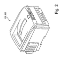
- FIG. 2 is a schematic perspective view of the image forming device of FIG. 1 .
- FIG. 3 is a cross sectional view of a structure of the fuser of the image forming device.
- FIG. 4 is a block diagram showing a control structure of the image forming device in a first embodiment.
- FIG. 5A is a flow diagram showing a first half of a control flow of the fuser when the image forming device of the first embodiment that was in the waiting mode starts image forming operation.
- FIG. 5B is a flow diagram showing a second half of a control flow of the fuser when the image forming device of the first embodiment starts image forming operation.
- FIG. 6 is a table showing a condition of a temperature increase and fusing speed of the pressure application roller of the fuser in the first embodiment.
- FIG. 7A is a time chart showing temperature change of the pressure application roller of the fuser in the first embodiment.
- FIG. 7B is a time chart showing a control of the fusing speed of the fuser in the first embodiment.
- FIG. 8 is a block diagram showing a control structure of an image forming device in a second embodiment.
- FIG. 9 is a flow diagram showing a control flow of the fuser when the image forming device of the second embodiment that was in the waiting mode starts image forming operation.
- FIG. 10A is a time chart showing a control of temperature change of the pressure application roller of the fuser in the second embodiment.
- FIG. 10B is a time chart showing a control of the fusing speed of the fuser in the second embodiment.
- FIGS. 1-7 An explanation of an image forming device according to a first embodiment is given below with reference to FIGS. 1-7 .
- FIG. 1 is a cross sectional view of an image processing device of the first embodiment.
- a tandem system printer device is used, for example.
- FIG. 2 is a schematic perspective view of the image forming device 100 .
- the image forming device 100 includes a sheet feeding part 16 , an image forming part 7 , a fuser 4 , a double-sided printing unit 8 , an ejecting unit 9 and an ejecting tray (cover) 19 , and has a structure to form images on a recording sheet S.
- the structure of the image forming device 100 is explained along with a flow of printing operation.
- a sheet feeding part 16 transfers the recording sheet S.
- the sheet feeding part 16 includes a sheet feeding cassette 21 , a sheet feeding roller 22 , a resist roller 23 or the like.
- the recording sheet S that is carried from the sheet feeding cassette 21 by rotation of the sheet feeding roller 22 is sent to the resist roller 23 , and further is sent along with a transfer carrying belt 15 , and reaches the image forming part 7 .
- the image forming part 7 is equipped with four image forming units 3 that respectively include different colors (total four colors). Furthermore, the four image forming units 3 are aligned in order.
- FIG. 1 illustrates the alignment in which black (K), yellow (Y), magenta (M) and cyan (C) are arranged from right to left.
- toner cartridges 2 -K, 2 -Y, 2 -M and 2 -C are equipped with each image forming unit 3 corresponding to its color.
- the image forming units 3 and the toner cartridges 2 -K, 2 -Y, 2 -M and 2 -C are separable.
- the four kinds of toner cartridges 2 -K, 2 -Y, 2 -M and 2 -C have an identical structure except for the color of the stored developing agent.
- the image forming part 7 has a structure such that the image forming units 3 and printing heads 17 contact each other when the cover 19 closes.
- Each image forming unit 3 includes a photoreceptor drum 10 , a charger 11 , a developing roller 12 and a cleaner 13 .
- the surrounding of the photoreceptor drum 10 is formed from photo-conductive material, and the charger 11 , the developing roller 12 and the cleaner 13 are arranged respectively near the photoreceptor drum 10 .
- a transferring device 14 is impressed to the photoreceptor drum 10 in which the transfer carrying belt 15 is disposed therebetween.
- the photoreceptor drum 10 rotates in a sheet transferring direction and its surface is uniformly electronically charged by electrons provided from the charger 11 .
- the printing head 17 forms an electrostatic latent image on a surface of the photoreceptor drum 10 by exposures (or optical writing processes) based on printing information.
- the developing roller 12 forms a toner image on a top surface of the recording sheet S by performing developing processing.
- the toner image that is formed on each surface of the photoreceptor drum 10 is formed with the each color toner that is stored in the respective toner cartridge 2 .
- the toner image formed on the surface of the photoreceptor drum 10 reaches a position of the transferring device 14 in accordance with rotation of the photoreceptor drum 10 , and is transferred on the top surface of the recording sheet S that moves beneath the photoreceptor drums 10 as indicated by the directional arrows, and the printing process is performed.
- the recording sheet S to which the toner image is transferred at each image forming unit 3 moves as indicated by the directional arrows on the transfer carrying belt 15 along with the movement of the transfer carrying belt 15 , and heat fusing process is performed at the fuser 4 .
- the toner images of the several colors that are transferred on the top side of the recording sheet S are fused, then fixed on the recording sheet S.
- the recording sheet S on which the toner image is fused by the fuser 4 is either carried to the ejecting unit 9 , then ejected to the ejecting tray 19 , or carried to the double-sided printing unit 8 through a switching plate 20 when double-sided printing needs to be performed, and image forming on the back side of the recording sheet S is performed again at the image forming part 7 .
- FIG. 3 is a cross sectional pattern diagram showing a structure of the fuser 4 .
- the fuser 4 includes the pressure application unit 5 which includes a heat application roller 6 as a heat application rotation member and a pressure application roller 34 as a pressure application rotation member.
- Two cylinder shaped heaters 33 are disposed inside of the heat application roller 6 as heaters.
- the top part of the heat application roller 6 includes a temperature sensor 35 .
- the temperature sensor 35 detects the top surface temperature of the heat application roller 6 .
- the pressure application unit 5 is configured with a pressure application belt 32 , a pressure application roller 34 , a pad 36 and a temperature sensor 37 as a detector for detecting the surface temperature of the pressure application roller 34 .
- the pressure application belt 32 surrounds the pressure application roller 34 and the pad 36 and rotates along with the rotation of the pressure application roller 34 .
- the temperature sensor 37 detects the bottom surface temperature of the pressure application roller 34 as a surface temperature of the pressure application rotating member.
- the heat application roller 6 and the peripheral side of the pressure application belt 32 which has its back side pressured by the pressure application roller 34 and the pad 36 , press the recording sheet S from both sides.
- the portion of the pressure application belt 32 , which contacts (or that is biased against) the heat application roller 6 is defined as a nip part (or contacting part).
- the pad 36 is disposed so as to increase a nip length of the pressure application belt 32 with respect to a rotating direction of the belt 32 by pressuring the pressure application belt 32 from its back side together with the pressure application roller 34 .
- material of the pad 36 is heat resistant, heat insulated, has adequate rigidity, and does not cause heat deformation.
- An example of a material that can be used for the pad 36 is a rigid metal (for example, steel).
- a cloth that has heat insulation and heat resistance properties, and that that is coated with fluorine contained resin on its surface may be used.
- Example of such a cloth includes woven glass fiber cloth and aramid fiber clothe.
- FIG. 4 is a block diagram showing a control structure of the image forming device 100 .
- the controller 40 is a central processing unit (CPU) 41 that includes a fuse rotation speed controlling part 44 or the like, a random-access memory (RAM) 42 and a read-only memory (ROM) 43 as a main control structure.
- the controller 40 is electronically connected to the image forming device 7 , the sheet feeding part 16 and the fuser 4 , as well as to the fuse driving part 30 that drives the fuser 4 .
- temperature information sent from the temperature sensor 35 of the heat application roller 6 and the temperature sensor 37 of the pressure application roller 34 that are the structure elements of the fuser 4 are input into analog digital converting input terminals (AD input terminals) of the CPU 41 .
- the temperature sensor 37 of the pressure application roller 34 is connected to an AD input terminal of the fuse rotation speed controlling part 44 of the CPU 41 .
- the CPU 41 reads necessary programs from the ROM 43 and uniformly controls the operations of the image forming part 7 , the sheet feeding part 16 and the fuser 4 , and executes the image forming operations.
- the RAM 42 is used as a work area when the CPU 41 executes the control programs.
- the controller 40 executes the image forming operations, receives a detection signal from the temperature sensor 35 , and controls power supply amount to the heater 33 in order to maintain the temperature of the heat application roller 6 to the predetermined fusing temperature by monitoring the temperature of the heat application roller 6 .
- the controller 40 receives a detection signal from the temperature sensor 35 and further determines the rotation speeds of the heat application roller 6 and the pressure application roller 34 according to the received information and the data stored in the fuse rotating speed controlling part 44 .
- the image forming operations are executed. During the image forming operations, a toner image is formed at the image forming part 7 , then the toner image is transferred to the recording sheet S.
- the recording sheet S to which the toner image (non-fused image) is transferred is carried with being sandwiched to the contacting part of the heat application roller 6 and the pressure application unit 5 . In other words, the recording sheet S is carried to the nip part.
- the toner image is fused by heat and pressure, and the recording sheet S is ejected on the ejecting tray 19 through the ejecting unit 9 .
- the image forming device 100 goes into a waiting mode until receiving the next job.
- the waiting mode rotations of the heat application roller 6 and the pressure application roller 34 of the fuser 4 are suspended.
- the heat application roller 6 is controlled so as to maintain the fusing temperature (190° C. in the present invention) by heating using the heater 33 .
- the pressure application roller 34 has a structure to receive the heat from the heat application roller 6 through the pressure application belt 32 by rotating as mentioned above, and to maintain the predetermined temperature (120° C. in the present invention), heat transmission from the heat application roller 6 to the pressure application roller 34 decreases in the waiting mode in which the rotation is suspended. As a result, the surface temperature of the pressure application roller 34 that is sensed by the temperature sensor 37 gradually decreases.
- FIGS. 5A and 5B are flow diagrams showing the control of the fuser 4 when the image forming device in the waiting mode starts image forming operation.
- the warm-up processing starts as shown at S 1 , performs heat processing of the heater 33 , then starts rotation processing of the fuser 4 at S 2 .
- the fuser 4 at this point rotates the heat application roller 6 and the pressure application roller 34 at a fusing speed of 150 mm/s that is equivalent to the fusing rotation speed at the time of printing.
- This fusing speed of 150 mm/s which is equivalent to the fusing rotation speed at the time of printing, is the standard speed.
- Next S 3 is a process to monitor whether the constant time t 1 has elapsed after the warm-up started, and judges whether or not the constant time t 1 has elapsed after the warm-up started.
- processing proceeds to S 4 .
- processing returns to S 3 and continue the process until the constant time t 1 is elapsed.
- processing from S 5 to S 8 proceeds to S 10 from S 13 respectively, depending on the detected temperature increase value ⁇ T, and the fusing speed of the heat application roller 6 and the pressure application roller 34 is determined.
- processing determines whether or not the temperature increase value ⁇ T is less than 50° C. When it is less than 50° C. (YES), processing proceeds to S 10 , the fusing speed is set to 160 mm/s which is faster than the standard speed and printing speed of 150 mm/s. When the temperature increase value ⁇ T is more than 50° C., processing proceeds to S 6 .
- processing judges whether or not temperature increase value ⁇ T is equal to or more than 50° C. and less than 55° C.
- processing proceeds to S 11 , and the fusing speed is set to 155 mm/s which is faster than the printing speed but slower than the fusing speed set at S 10 .
- processing proceeds to S 7 .
- processing judges whether or not the temperature increase value ⁇ T is equal to or more than 55° C. and less than 60° C.
- processing proceeds to S 14 , and the fusing speed is set to 150 mm/s that is a standard speed.
- processing proceeds to S 8 .
- processing judges whether or not the temperature increase value ⁇ T is equal to or more than 60° C. and less than 65° C.
- processing proceeds to S 12 , and the fusing speed is set to 145 mm/s.
- processing proceeds to S 13 , and the fusing speed is set to 140 mm/s.
- the fusing speed does not change from 150 mm/s, which is same speed as the printing speed.
- the temperature increase value ⁇ T is smaller, that is, equal to or more than 50° C. and less than 55° C.
- the fusing speed is changed to 155 mm/s which is faster than the printing speed.
- the temperature increase value ⁇ T is less than 50° C.
- the fusing speed is increased to 160 mm/s.
- the fusing speed is set to 145 mm/s, which is slower than the printing speed. Moreover, when the temperature increase value ⁇ T is equal to or more than 65° C., the fusing speed is decreased to 140 mm/s.
- processing proceeds to S 14 .
- processing continues until both of the heat application roller 6 and the pressure application roller 34 reach the predetermined temperature, and when the predetermined temperature is detected (YES), processing proceeds to S 15 , and processing to return the fusing speed to the standard value of the printing speed of 150 mm/s performed.
- preparation of fusing is completed, and printing and fusing operations are performed at S 16 .
- FIGS. 7A and 7B are time charts showing the temperature change of the pressure application roller 34 versus time and the control processing of the fusing speed versus time, respectively.
- a horizontal axis of FIGS. 7A and 7B shows the elapsed time since the warm-up started.
- the vertical axis of FIG. 7A shows changes of the temperature increase value ⁇ T of the pressure application roller 34
- the vertical axis of FIG. 7B shows the changes of the fusing speed controlled with respect to the temperature increase value ⁇ T of the pressure application roller 34 .
- the fusing speed is changed to Speed-C, which is slower than the printing speed, in order to decrease the heat transmission amount to the pressure application roller 34 from the heat application roller 6 .
- the temperature increase changes as shown at broken lines a and b in FIG. 7B because it becomes possible to ideally maintain the heat transmission amount to the pressure application roller 34 from the heat application roller 6 when the fusing speed is changed as shown in FIG. 7B according to the temperature increase of the pressure application roller 34 at t 1 . Accordingly, at t 3 until the warm-up is completed, the overshoot phenomenon at the solid line (c) does not occur, and the phenomenon in which the temperature of the solid line (a) does not fully increase at t 3 does not occur.
- the fusing speed is changed based on the temperature of the pressure application roller 34 .
- time necessary for homogenizing the surface temperature of the pressure application roller 34 after the target fusing temperature is reached can be stabilized without being largely influenced by the temperature difference of the heat application roller 6 and the pressure application roller 34 , or the heat retaining condition inside of the pressure application roller 34 .
- the warm-up time is shortened because the pressure application roller 34 can be adequately heated.
- the settling time is also can be reduced by reducing the amount of the overshoot or undershoot with respect to the target fusing temperature.
- the second embodiment of the image forming device of the present invention is explained with reference to FIGS. 8 and 10 . Moreover, to explain an image processing device 200 of the present embodiment, the same numbers are used for the same structural elements as in the image forming device 100 .
- FIG. 8 is a block diagram showing the control structure of the image forming device 200 .
- a temperature difference calculation part 45 is added as a structural element of the CPU 41 of the controller 40 in the image forming device 100 of the first embodiment.
- the detected temperature is input from the temperature sensor 37 of the pressure application roller 34 .
- the temperature difference calculation part 45 performs a temperature comparison after a predetermined interval to calculate the difference between the standard temperature increase and the actual temperature increase of the pressure application roller 34 , and inputs the successive temperature comparison information in the fuse rotation speed controlling part 44 .
- FIG. 9 is a flow diagram showing control of a fuser 4 when the image forming device 200 that is in a waiting mode starts the image forming operation.
- the processing from S 1 to S 2 is the same as the first embodiment. Initially, when the image forming device 200 shifts to the image forming operation mode from the waiting mode, warm-up processing is started at S 1 , heat processing of a heater 33 is performed, and rotation processing of the fuser 4 is started at S 2 . At this point, the fusing speed of the fuser 4 is 150 mm/s, which is the same as a fusing speed at the printing operation.
- the time counter is reset in order to monitor the temperature increase of the pressure application roller 34 at a constant interval.
- processing judges whether or not the constant time ⁇ t has elapsed at the time counter.
- processing proceeds to S 23 .
- processing returns to S 21 .
- the temperature difference ⁇ T of the temperature increase value and the standard temperature increase value (standard temperature profile) of the pressure application roller 34 is detected, and processing proceeds to S 24 .
- processing proceeds to S 15 , and performs the processing to return the fusing speed of the fuser 4 to the printing speed of 150 mm/s. At this point, preparation for fusing is completed, and the printing and fusing processing are performed at S 16 .
- FIGS. 10A and 10B are time charts showing elapsed time of the repeated above-described processing on the horizontal axis, and the temperature change of the pressure application roller 34 and an example of fusing speed changes of the fuser 4 on the vertical axis.
- the aforementioned temperature difference ⁇ Ta exists at t 1 , which is the first constant time that elapses after the warm-up begins.
- the fusing speed is changed to Speed-A, which is faster than printing speed (Speed-B).
- the temperature difference at t 2 after the constant time has elapsed is detected to be higher than the standard temperature.
- the temperature of the pressure application roller 34 is higher by ⁇ Tb.
- the fusing speed of the fuser 4 is decreased.
- the fusing speed is set at Speed-C, which is the intermediate speed between Speed-A and Speed-B.
- Speed-C is the intermediate speed between Speed-A and Speed-B.
- This processing is repeated at a constant interval, and the changing process of the fusing speed of the fuser 4 that uses the aforementioned temperature difference ends at the time tn, which is the timing of when the temperature reaches the fusing capable temperature, and processing proceeds to return to Speed-B, which is for printing.
- the second embodiment during warm-up processing when shifting to the image forming operation mode from the waiting mode, because the difference between the temperature of the pressure application roller 34 and the standard temperature increase is repeatedly obtained at a constant interval during warm-up, and the fusing speed is changed, more accurate control without having dispersion of the temperature of the pressure application roller 34 becomes possible compared to the first embodiment.
- the present invention can be applied to temperature increase control of the fuser 4 when power is turned on because it can effectively control the temperature increase while maintaining a balance between temperature increase of the pressure application roller 34 and the heat application roller 6 .
- the explanation of the pad 36 and the pressure application belt 32 as structure of the pressure application unit 5 was provided in connection with the first and second embodiments.
- the present invention can be applied to a structure which does not include the pad 36 and the pressure application belt 32 .
- it can be applied to the structure of the pressure application roller 34 and the temperature sensor 37 .
- the printer device especially the fuser of the tandem system printer device is explained.
Landscapes
- Physics & Mathematics (AREA)
- General Physics & Mathematics (AREA)
- Fixing For Electrophotography (AREA)
Abstract
Description
S=ΔT×α+(Current Speed) (formula 1)
where α is a constant number.
Claims (8)
Applications Claiming Priority (2)
| Application Number | Priority Date | Filing Date | Title |
|---|---|---|---|
| JP2008273553A JP5352181B2 (en) | 2008-10-23 | 2008-10-23 | Image forming apparatus |
| JP2008-273553 | 2008-10-23 |
Publications (2)
| Publication Number | Publication Date |
|---|---|
| US20100104307A1 US20100104307A1 (en) | 2010-04-29 |
| US8229312B2 true US8229312B2 (en) | 2012-07-24 |
Family
ID=42117620
Family Applications (1)
| Application Number | Title | Priority Date | Filing Date |
|---|---|---|---|
| US12/588,322 Expired - Fee Related US8229312B2 (en) | 2008-10-23 | 2009-10-13 | Image forming device and fuser |
Country Status (2)
| Country | Link |
|---|---|
| US (1) | US8229312B2 (en) |
| JP (1) | JP5352181B2 (en) |
Cited By (2)
| Publication number | Priority date | Publication date | Assignee | Title |
|---|---|---|---|---|
| US20140147150A1 (en) * | 2012-11-29 | 2014-05-29 | Oki Data Corporation | Fuser control device, fuser control method and image forming apparatus |
| US20150093136A1 (en) * | 2013-09-30 | 2015-04-02 | Kyocera Document Solutions Inc. | Fixing device and image forming apparatus |
Families Citing this family (12)
| Publication number | Priority date | Publication date | Assignee | Title |
|---|---|---|---|---|
| JP2011064726A (en) * | 2009-09-15 | 2011-03-31 | Ricoh Co Ltd | Fixing device and image forming apparatus |
| JP5454254B2 (en) * | 2010-03-16 | 2014-03-26 | 株式会社リコー | Image forming apparatus |
| JP5514708B2 (en) * | 2010-12-14 | 2014-06-04 | 株式会社沖データ | Image forming apparatus |
| US8731423B2 (en) * | 2011-01-19 | 2014-05-20 | Kabushiki Kaisha Toshiba | Image forming apparatus and control device and control method of fixing device |
| JP2013076878A (en) | 2011-09-30 | 2013-04-25 | Konica Minolta Business Technologies Inc | Image forming apparatus |
| JP5945515B2 (en) * | 2012-04-17 | 2016-07-05 | 株式会社沖データ | Image forming apparatus |
| JP2014002191A (en) * | 2012-06-15 | 2014-01-09 | Sharp Corp | Fixing device, image forming apparatus, temperature control method of fixing device, program, and recording medium |
| JP5854238B2 (en) | 2013-05-07 | 2016-02-09 | コニカミノルタ株式会社 | Fixing apparatus and image forming apparatus |
| JP6465578B2 (en) * | 2013-08-07 | 2019-02-06 | キヤノン株式会社 | Image forming apparatus |
| JP6372313B2 (en) * | 2014-10-31 | 2018-08-15 | 株式会社リコー | Fixing apparatus and image forming apparatus |
| US10152006B2 (en) * | 2015-06-26 | 2018-12-11 | Ricoh Company, Ltd. | Fixing device and image forming apparatus |
| JP6897293B2 (en) * | 2017-05-11 | 2021-06-30 | 株式会社リコー | Fixing device and image forming device |
Citations (4)
| Publication number | Priority date | Publication date | Assignee | Title |
|---|---|---|---|---|
| JPH1138802A (en) * | 1997-07-15 | 1999-02-12 | Fuji Xerox Co Ltd | Heat fixing device |
| JPH11133802A (en) * | 1997-10-27 | 1999-05-21 | Canon Inc | Image forming apparatus and warm-up operation control method thereof |
| JP2005062700A (en) * | 2003-08-19 | 2005-03-10 | Fuji Xerox Co Ltd | Image forming apparatus |
| JP2007033618A (en) | 2005-07-25 | 2007-02-08 | Konica Minolta Business Technologies Inc | Fixing device, image forming apparatus, and method for driving fixing device |
Family Cites Families (3)
| Publication number | Priority date | Publication date | Assignee | Title |
|---|---|---|---|---|
| JPH0727419B2 (en) * | 1990-09-25 | 1995-03-29 | 富士ゼロックス株式会社 | Temperature control method |
| JPH10161467A (en) * | 1996-11-26 | 1998-06-19 | Canon Inc | Image forming apparatus and stepping motor starting method |
| JP4557842B2 (en) * | 2005-08-31 | 2010-10-06 | キヤノン株式会社 | Fixing apparatus and driving method thereof |
-
2008
- 2008-10-23 JP JP2008273553A patent/JP5352181B2/en not_active Expired - Fee Related
-
2009
- 2009-10-13 US US12/588,322 patent/US8229312B2/en not_active Expired - Fee Related
Patent Citations (4)
| Publication number | Priority date | Publication date | Assignee | Title |
|---|---|---|---|---|
| JPH1138802A (en) * | 1997-07-15 | 1999-02-12 | Fuji Xerox Co Ltd | Heat fixing device |
| JPH11133802A (en) * | 1997-10-27 | 1999-05-21 | Canon Inc | Image forming apparatus and warm-up operation control method thereof |
| JP2005062700A (en) * | 2003-08-19 | 2005-03-10 | Fuji Xerox Co Ltd | Image forming apparatus |
| JP2007033618A (en) | 2005-07-25 | 2007-02-08 | Konica Minolta Business Technologies Inc | Fixing device, image forming apparatus, and method for driving fixing device |
Cited By (4)
| Publication number | Priority date | Publication date | Assignee | Title |
|---|---|---|---|---|
| US20140147150A1 (en) * | 2012-11-29 | 2014-05-29 | Oki Data Corporation | Fuser control device, fuser control method and image forming apparatus |
| US9188915B2 (en) * | 2012-11-29 | 2015-11-17 | Oki Data Corporation | Fuser control device, fuser control method and image forming apparatus |
| US20150093136A1 (en) * | 2013-09-30 | 2015-04-02 | Kyocera Document Solutions Inc. | Fixing device and image forming apparatus |
| US9329538B2 (en) * | 2013-09-30 | 2016-05-03 | Kyocera Document Solutions Inc. | Fixing device and image forming apparatus |
Also Published As
| Publication number | Publication date |
|---|---|
| JP2010102126A (en) | 2010-05-06 |
| JP5352181B2 (en) | 2013-11-27 |
| US20100104307A1 (en) | 2010-04-29 |
Similar Documents
| Publication | Publication Date | Title |
|---|---|---|
| US8229312B2 (en) | Image forming device and fuser | |
| US8027607B2 (en) | Image forming apparatus | |
| US8918003B2 (en) | Fixing device | |
| US8699904B2 (en) | Fixing device and image forming apparatus capable of suppressing variation image density | |
| EP2442187B1 (en) | Fixing device, fixing device control method, and image forming apparatus | |
| US8135298B2 (en) | Image forming apparatus and image forming method for controlling image formation based on a temperature of a fusing rotating body | |
| US8331820B2 (en) | Fixing device and image forming apparatus using same | |
| US9874838B1 (en) | System and method for controlling a fuser assembly of an electrophotographic imaging device | |
| US7593658B2 (en) | Image forming apparatus | |
| US8620173B2 (en) | Image forming device with fusion device driven based on surface temperature of fusion roller and pressure application roller | |
| US9098028B2 (en) | Image forming apparatus | |
| EP1560079A2 (en) | Image processing apparatus with preheating control for fuser | |
| EP2031463A2 (en) | Image forming apparatus | |
| US8737860B2 (en) | Image forming apparatus and image forming method | |
| JP2013076878A (en) | Image forming apparatus | |
| JP2009223058A (en) | Fixing unit and image forming apparatus | |
| JPH07230231A (en) | Fixing device | |
| JP4953574B2 (en) | Image forming apparatus | |
| US9195187B2 (en) | Image forming apparatus | |
| JP5552850B2 (en) | Fixing control method, fixing device, and image forming apparatus | |
| JP2005024667A (en) | Image forming apparatus | |
| US10012933B2 (en) | Fixing device and image forming apparatus | |
| US20240377774A1 (en) | Fusing based on belt temperature | |
| JP2007025252A (en) | Fixing control of image forming device | |
| JP2010026435A (en) | Fixing device and image forming apparatus equipped therewith |
Legal Events
| Date | Code | Title | Description |
|---|---|---|---|
| AS | Assignment |
Owner name: AKI DATA CORPORATION,JAPAN Free format text: ASSIGNMENT OF ASSIGNORS INTEREST;ASSIGNOR:SHINYAMA, HIDEKI;REEL/FRAME:023402/0095 Effective date: 20091009 Owner name: AKI DATA CORPORATION, JAPAN Free format text: ASSIGNMENT OF ASSIGNORS INTEREST;ASSIGNOR:SHINYAMA, HIDEKI;REEL/FRAME:023402/0095 Effective date: 20091009 |
|
| STCF | Information on status: patent grant |
Free format text: PATENTED CASE |
|
| FEPP | Fee payment procedure |
Free format text: PAYOR NUMBER ASSIGNED (ORIGINAL EVENT CODE: ASPN); ENTITY STATUS OF PATENT OWNER: LARGE ENTITY |
|
| FPAY | Fee payment |
Year of fee payment: 4 |
|
| FEPP | Fee payment procedure |
Free format text: MAINTENANCE FEE REMINDER MAILED (ORIGINAL EVENT CODE: REM.); ENTITY STATUS OF PATENT OWNER: LARGE ENTITY |
|
| LAPS | Lapse for failure to pay maintenance fees |
Free format text: PATENT EXPIRED FOR FAILURE TO PAY MAINTENANCE FEES (ORIGINAL EVENT CODE: EXP.); ENTITY STATUS OF PATENT OWNER: LARGE ENTITY |
|
| STCH | Information on status: patent discontinuation |
Free format text: PATENT EXPIRED DUE TO NONPAYMENT OF MAINTENANCE FEES UNDER 37 CFR 1.362 |
|
| FP | Lapsed due to failure to pay maintenance fee |
Effective date: 20200724 |