US8218066B2 - Interchangeable lens, interchangeable lens system and camera system - Google Patents
Interchangeable lens, interchangeable lens system and camera system Download PDFInfo
- Publication number
- US8218066B2 US8218066B2 US10/903,627 US90362704A US8218066B2 US 8218066 B2 US8218066 B2 US 8218066B2 US 90362704 A US90362704 A US 90362704A US 8218066 B2 US8218066 B2 US 8218066B2
- Authority
- US
- United States
- Prior art keywords
- interchangeable lens
- camera
- mount
- lens
- protruding portion
- Prior art date
- Legal status (The legal status is an assumption and is not a legal conclusion. Google has not performed a legal analysis and makes no representation as to the accuracy of the status listed.)
- Expired - Fee Related, expires
Links
Images


Classifications
-
- G—PHYSICS
- G03—PHOTOGRAPHY; CINEMATOGRAPHY; ANALOGOUS TECHNIQUES USING WAVES OTHER THAN OPTICAL WAVES; ELECTROGRAPHY; HOLOGRAPHY
- G03B—APPARATUS OR ARRANGEMENTS FOR TAKING PHOTOGRAPHS OR FOR PROJECTING OR VIEWING THEM; APPARATUS OR ARRANGEMENTS EMPLOYING ANALOGOUS TECHNIQUES USING WAVES OTHER THAN OPTICAL WAVES; ACCESSORIES THEREFOR
- G03B17/00—Details of cameras or camera bodies; Accessories therefor
- G03B17/02—Bodies
- G03B17/12—Bodies with means for supporting objectives, supplementary lenses, filters, masks, or turrets
- G03B17/14—Bodies with means for supporting objectives, supplementary lenses, filters, masks, or turrets interchangeably
-
- G—PHYSICS
- G03—PHOTOGRAPHY; CINEMATOGRAPHY; ANALOGOUS TECHNIQUES USING WAVES OTHER THAN OPTICAL WAVES; ELECTROGRAPHY; HOLOGRAPHY
- G03B—APPARATUS OR ARRANGEMENTS FOR TAKING PHOTOGRAPHS OR FOR PROJECTING OR VIEWING THEM; APPARATUS OR ARRANGEMENTS EMPLOYING ANALOGOUS TECHNIQUES USING WAVES OTHER THAN OPTICAL WAVES; ACCESSORIES THEREFOR
- G03B19/00—Cameras
- G03B19/02—Still-picture cameras
- G03B19/12—Reflex cameras with single objective and a movable reflector or a partly-transmitting mirror
Definitions
- the present invention relates to interchangeable lenses with different amounts of protrusion from a mount reference surface toward an image plane used for a camera system including a plurality of cameras having the same mount structure, and the camera system.
- Japanese Patent Publication No. 3217273 discloses a camera system, camera body and interchangeable lens which have a common mount but imposes restrictions on the mounting of interchangeable lenses having a back focus of a certain size or smaller.
- This camera system, etc. provides a flange portion inside the mount of the conventional camera body and restricts the mounting of the interchangeable lens by causing a fixed protrusion provided on the interchangeable lens with a short back focus to contact this flange portion.
- Japanese Patent Publication No. 3217273 also discloses the fact that it is possible to reduce the size of a quick return mirror of a camera with a short back focus compared to a quick return mirror of a camera with a long back focus.
- the second interchangeable lens includes a protruding portion protruding from a mount reference surface toward an image plane, which has a larger protruding amount than that of the first interchangeable lens, and has the same flange back as that of the first interchangeable lens.
- the first interchangeable lens is mounted on the first camera.
- the second camera includes a second wall portion inside its mount provided at a position retreated from the protruding portion of the second interchangeable lens, and the second camera includes a mirror member which rotates closer to an image-pickup surface than the second wall portion between a first position at which a luminous flux directed from an object to the image-pickup surface is reflected toward a finder optical system and a second position retracted from the luminous flux, and the rotation center of the mirror member is positioned on the opposite side of the finder optical system with respect to a plane including an in-plane direction of the mirror member.
- the second interchangeable lens is mounted on the second camera.
- a camera system of the present invention as a further aspect comprises a first interchangeable lens, and a second interchangeable lens which includes a protruding portion protruding from a mount reference surface toward an image surface, which has a larger protruding amount than that of the first interchangeable lens, and has the same flange back as that of the first interchangeable lens.
- the camera system further comprises first camera and second camera.
- the first camera includes a first wall portion inside its mount.
- the first interchangeable lens is mounted on the first camera. The first camera prevents the mounting of the second interchangeable lens by the protruding portion of the second interchangeable lens contacting the first wall portion.
- the second camera includes a second wall portion inside its mount provided at a position retreated from the protruding portion of the second interchangeable lens.
- the first and second interchangeable lenses are mounted on the second camera.
- the second camera further includes a mirror member.
- the mirror member rotates closer to an image-pickup surface than the second wall portion between a first position at which a luminous flux directed from an object to the image-pickup surface is reflected toward a finder optical system and a second position retracted from the luminous flux.
- the rotation center of the mirror member is positioned on the opposite side of the finder optical system with respect to a plane including an in-plane direction on the mirror member.
- FIG. 1 is a cross-sectional view of a first interchangeable lens barrel according to Embodiment 1 of the present invention
- FIG. 2 is a cross-sectional view of a second interchangeable lens barrel according to Embodiment 1 of the present invention.
- FIG. 3 is a cross-sectional view when the first interchangeable lens barrel according to Embodiment 1 of the present invention is mounted on a first camera body;
- FIG. 6 is a cross-sectional view when an attempt is made to mount the second interchangeable lens barrel according to Embodiment 1 of the present invention in the first camera body;
- FIG. 7 is a front view when the first interchangeable lens barrel according to Embodiment 1 of the present invention is mounted on the first camera body;
- FIG. 8 is a front view when the second interchangeable lens barrel according to Embodiment 1 of the present invention is mounted on the second camera body;
- FIG. 10 is a side view when the second interchangeable lens barrel according to Embodiment 1 of the present invention is mounted on the second camera body;
- FIG. 15 is a cross-sectional view and a front view of the first interchangeable lens according to Embodiment 2 of the present invention.
- FIG. 16 is a cross-sectional view and a front view of the second interchangeable lens according to Embodiment 2 of the present invention.
- FIG. 17 is a cross-sectional view and a front view of the first camera body according to Embodiment 2 of the present invention.
- FIG. 20 is a perspective view of a second camera according to Embodiment 3 of the present invention.
- FIG. 21 is a side view of a first interchangeable lens according to Embodiment 3 of the present invention.
- FIG. 22 is a side view of a second interchangeable lens according to Embodiment 3 of the present invention.
- FIG. 23 is a perspective view of the second interchangeable lens according to Embodiment 3 of the present invention.
- FIG. 25 is a cross-sectional view of the second interchangeable lens according to Embodiment 3 of the present invention.
- FIG. 26 is a cross-sectional view showing a state in which the first interchangeable lens according to Embodiment 3 of the present invention is mounted on the first camera;
- FIG. 28 is a cross-sectional view showing a state in which the second interchangeable lens according to Embodiment 3 of the present invention cannot be mounted on the first camera;
- FIG. 29 is a cross-sectional view showing a state in which the second interchangeable lens according to Embodiment 3 of the present invention cannot be mounted on the first camera;
- FIG. 31 is a front view showing a phase relationship between the bayonet lugs of the second interchangeable lens and the second camera according to Embodiment 3 of the present invention.
- FIG. 33 is a front view showing a phase relationship between the bayonet lugs of the second interchangeable lens and the first camera according to Embodiment 3 of the present invention:
- FIG. 35 is a front view showing a phase relationship between the bayonet lugs of the second interchangeable lens and the first camera according to Embodiment 3 of the present invention.
- FIG. 36 is a cross-sectional view showing a state in which the second interchangeable lens according to Embodiment 3 of the present invention cannot be mounted on the first camera;
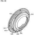
- FIG. 39 is a perspective view showing a modification example of the mount provided on the second interchangeable lens according to Embodiment 3 of the present invention.
- FIG. 40 is a perspective view showing a modification example of the mount provided on the second interchangeable lens according to Embodiment 3 of the present invention.
- FIG. 41 is a perspective view showing a modification example of the mount provided on the second interchangeable lens according to Embodiment 3 of the present invention.
- FIG. 42 is a cross-sectional view around a quick return mirror of the second camera according to Embodiment 3 of the present invention.
- FIG. 1 to FIG. 6 show a camera system including an interchangeable lens and camera body which is Embodiment 1 of the present invention.
- FIG. 1 is a cross-sectional view showing a first interchangeable lens 1 for a 35 mm film camera, which holds a first optical lens 2 and a second optical lens 3 in a lens barrel.
- bayonet lugs 4 for bayonet coupling with a camera body are provided and the bayonet lugs 4 are disposed closer to an image-pickup surface 100 than a mount reference surface 5 located at a distance of a flange back “A” from the image-pickup surface 100 .
- the portion protruding from the mount reference surface 5 including the bayonet lug 4 toward the image-pickup surface corresponds to the protruding portion of the first interchangeable lens 1 .
- the distance from the mount reference surface 5 to the end face of the bayonet lug 4 on the image-pickup surface 100 side is represented by “B′”.
- the distance from the image-pickup surface 100 to the second optical lens 3 is represented by “C′”.
- the camera system is constructed so as to secure A-B′ ⁇ C′ to prevent the second optical lens 3 from being damaged when the first interchangeable lens 1 is singly placed on a desk, etc.
- FIG. 2 is a cross-sectional view schematically showing a second interchangeable lens 11 for a camera provided with an APS-C size image-pickup element (however, any image-pickup element of the size which is different from the APS-C size is also acceptable if it is smaller than the 35 mm film size), which holds a first optical lens 12 and a second optical lens 13 in a lens barrel.
- an APS-C size image-pickup element (however, any image-pickup element of the size which is different from the APS-C size is also acceptable if it is smaller than the 35 mm film size), which holds a first optical lens 12 and a second optical lens 13 in a lens barrel.
- bayonet lugs 4 for bayonet coupling with a camera body as in the case of the first interchangeable lens 1 are provide and the bayonet lugs 4 are disposed closer to an image-pickup surface 100 than a mount reference surface 5 located at a distance of a flange back “A” from the image-pickup surface 100 .
- a protruding portion 14 is formed closer to the image-pickup surface 100 than the bayonet lugs 4 and on the inner diameter side of the bayonet lugs 4 .
- the portion from the mount reference surface 5 to the end face of the protruding portion 14 on the image-pickup surface 100 side corresponds to the protruding portion according to the present claims, but the portion protruding from the bayonet lug 4 will be referred to as a “protrusion” for convenience of explanation here.
- a rubber ring 15 which is an elastic member, is fitted in on the entire circumference centered on the optical axis by means of its elasticity. Furthermore, the rubber ring 15 has a color tone and material different from those of the protruding portion 14 , which allows the user to easily visually recognize the rubber ring 15 .
- the second optical lens 13 is disposed closer to the image-pickup surface 100 compared to the first interchangeable lens 1 so as to take advantage of the protruding portion 14 and is constructed so as to shorten a back focus “C”. Furthermore, as in the case of the first interchangeable lens 1 , the camera system is constructed so as to secure A-B ⁇ C to prevent the second optical lens 13 from being damaged when the second interchangeable lens 11 is singly placed on a desk, etc.
- the ratio of the diameter of the protruding portion 14 to the protruding amount of protruding portion 14 is set to 3:1 or more and the rubber ring 15 also has the effect as a non-slip member.
- both lenses have the same distance “A” from the image-pickup surface 100 to the mount reference surface 5 and have the bayonet lug 4 formed at the same position and in the same shape.
- the protruding amount from the reference surface 5 toward the image-pickup surface 100 is designed to be “B′” ⁇ (B) and the back focuses from the image-pickup surface 100 to the respective second optical lenses are designed to be “C′”>(C)
- FIG. 3 is a schematic cross-sectional view showing a state in which the first interchangeable lens 1 is mounted on a first camera body 21 (e.g., a camera body for a 35 mm film) which allows mounting of only the first interchangeable lens 1 .
- the first camera body 21 is provided with a mount reference surface 22 on the camera body side which contacts the mount reference surface 5 of the first interchangeable lens 1 and a bayonet structure 23 on the camera body side which engages with the bayonet lug 4 .
- Reference numeral 24 denotes a quick return mirror and the quick return mirror 24 reflects part of a luminous flux which has passed through the first optical lens 2 and the second optical lens 3 to a finder system (not shown) and sends the rest of the luminous flux to a distance measuring system and photometric system (not shown) through a semitransparent portion.
- the quick return mirror 24 moves up in the direction indicated by an arrow in the figure.
- the second camera body 31 is provided with a mount reference surface 22 on the camera body side which contacts the mount reference surface 5 of the first and second interchangeable lenses 1 and 11 , and a bayonet structure 23 on the camera body side which engages with the bayonet lug 4 .
- Reference numeral 32 denotes a quick return mirror and the quick return mirror 32 reflects part of a luminous flux which has passed through the first optical lens 2 and the second optical lens 3 to a finder system (not shown) and sends the rest of the luminous flux to a distance measuring system and photometric system (not shown) through a semitransparent portion.
- the quick return mirror 32 moves up in the direction indicated by an arrow in the figure.
- the quick return mirror 32 is the same as the quick return mirror 24 of the first camera body 21 in terms of functions and operations, but since the image-pickup element is smaller than a 35 mm film, the quick return mirror 32 can be smaller than the quick return mirror 24 and even when quick return mirror 32 moves up, the track thereof is small.
- FIG. 5 is a schematic cross-sectional view when the second interchangeable lens 11 is mounted on the second camera body 31 .
- the second camera body 31 is provided with a recess portion 33 to avoid the protruding portion 14 of the second interchangeable lens 11 .
- the quick return mirror is small as described above, even the second interchangeable lens 11 which is an interchangeable lens with a short back focus does not interfere with the quick return mirror 32 and the track thereof is designed to pass closer to the image-pickup surface 100 than the back end face (second wall portion) of the recess portion 33 which is provided at a position where the distance from the mount reference surface 22 on the camera body side is “F”.
- FIG. 6 is a schematic cross-sectional view when an attempt is made to mount the second interchangeable lens 11 on the first camera body 21 .
- a wall portion (first wall portion) 25 is provided at a position at a shorter distance “F′” from the mount reference surface 22 of the first camera body 21 than the distance “B” from the mount reference surface 5 to the end face of the rubber ring 15 (protrusion 14 ) on the image-pickup surface 100 side so as to prevent the second interchangeable lens 11 from being mounted on the first camera body 21 which is a 35 mm film camera.
- the rubber ring 15 is designed to contact the wall portion 25 of the first camera body 21 to prevent both the first camera body 21 and the second interchangeable lens 11 from being damaged.
- FIG. 7 to FIG. 10 Furthermore, an embodiment for preventing such wrong mounting will be explained using FIG. 7 to FIG. 10 .
- FIG. 7 is a front view of the first interchangeable lens 1 mounted on the first camera body 21 .
- the first camera body 21 is provided with a mounting index 26 to match the phase of the bayonet lug 4 when the first interchangeable lens 1 is mounted and the first interchangeable lens 1 is provided with a mounting index 6 .
- the mounting is completed by matching the phase of the mounting index 6 with the phase of the mounting index 26 , allowing the respective mount reference surfaces to contact each other and turning the first interchangeable lens 1 by a predetermined angle “D”.
- making the shape of the mounting index 34 corresponding to the first interchangeable lens 1 different from the shape of the mounting index 35 corresponding to the second interchangeable lens 11 visually alerts the user making it possible to further prevent wrong mounting and if a difference is provided in not only the shape but also color tone, a larger effect can be expected.
- the mounting is completed by matching the phases of the respective mounting indices and turning the interchangeable lens by a predetermined angle “D”.
- Reference numerals 120 and 130 denote interchangeable lenses, 120 denotes a second interchangeable lens having a small image size on the film surface (or photoreceiving surface of an image-pickup element) and 130 denotes a first interchangeable lens having a large image size.
- Reference numerals 140 and 150 denote camera bodies, 140 denotes a second camera body which allows mounting of the first and second interchangeable lenses 130 , 120 and 150 denotes a first camera body which does not allow mounting of the second interchangeable lens 120 .
- FIG. 11 shows a state in which the second interchangeable lens 120 is mounted on the second camera body 140 and
- FIG. 12 shows a state in which the second interchangeable lens 120 cannot be mounted on the first camera body 150 .
- FIG. 13 shows a state in which the first interchangeable lens 130 is mounted on the second camera body 140 and
- FIG. 14 shows a state in which the first interchangeable lens 130 is mounted on the first camera body 150 .
- the back end face of the back cover 103 on the camera side has a larger protruding amount from the mount reference surface 102 a (indicated by A in the figure) than that of the first interchangeable lens 130 which will be described later.
- Reference numeral 104 denotes damage prevention rubber
- 105 denotes a lens-side electric contact. Since the interchangeable lens body 101 is not directly related to this proposal, only its outline is expressed and detailed explanations thereof will be omitted.
- FIG. 17 shows a cross-sectional view and a front view of the second camera body 140 .
- Reference numeral 108 denotes a camera main body
- 109 denotes a bayonet mount on the camera body side
- 110 denotes a plurality of electric contact pins on the camera side
- 111 denotes a contact pin spring.
- the bayonet mount on the camera body side 109 is provided with a mount reference surface 109 a which is a positioning surface with respect to the interchangeable lens and bayonet lugs on the camera side 109 b .
- the electric contact pins 110 are biased by the contact pin spring 111 at positions corresponding to the electric contacts on the interchangeable lens side 105 toward the interchangeable lens.
- FIG. 16 suppose the distance in the direction of the optical axis from the mount reference surface 102 a of the first interchangeable lens 130 to the back end face of the first interchangeable lens 130 on the camera side is “B”( ⁇ A).
- “A” must be smaller than “D” so that the second interchangeable lens 120 is prevented from being mounted on the first camera body 150 .
- C and D must be larger than “B” so that the first interchangeable lens 130 can be mounted on the first and second camera bodies 150 , 140 .
- the bayonet lug 102 b of the mount of the second interchangeable lens 120 does not locate within a certain angle phase where the bayonet lug 109 b of the mount of the first camera body 150 does not exist and the end face on the camera side of the bayonet lug 102 b contacts the end face on the lens side of the bayonet lug 109 b
- the back end face on the camera side of the back cover 103 of the second interchangeable lens 120 draws away from the first wall portion 112 a of the first camera body 150 by an amount substantially corresponding to the thickness of the bayonet lug 102 b.
- Embodiment 3 will be explained using FIG. 19 to FIG. 41 in detail below.
- first and second cameras are digital cameras provided with an image-pickup element.
- front means an object side
- back will refer to an image plane or image-pickup element side.
- a plurality of electric contact pins 204 are provided in the lower part of the wall portion 205 . These electric contact pins 204 are used for communication with the first interchangeable lens mounted and power supply to the first interchangeable lens.
- a red, circular camera-side index (hereinafter referred to as “lens mounting index”) 208 is provided.
- the lens mounting index 208 serves as a mark to match the phase of bayonet lugs of the first interchangeable lens with the phase (between neighboring bayonet lugs 203 in the circumferential direction) of the first camera 201 where the bayonet lugs 203 do not exist when the first interchangeable lens is bayonet-coupled.
- FIG. 20 , FIG. 27 and FIG. 30 show a second camera (camera body) 301 .
- a ring-shaped mount 302 for mounting the first and second interchangeable lenses which will be described later is provided on the front of the second camera 301 .
- the front end face of this mount 302 serves as a reference surface (mount reference surface) 302 a when the first and second interchangeable lenses are mounted.
- bayonet lugs 303 for bayonet coupling with the first and second interchangeable lenses are formed at three locations in the circumferential direction at a certain distance behind the mount reference surface 302 a.
- the distance from the mount reference surface 302 a to the wall portion 305 is the same as the distance from the mount reference surface 202 a to the wall portion 205 in the first camera 201 (indicated by F′ in FIG. 28 ).
- a containing portion 307 capable of containing a protruding portion provided on the back end side of the second interchangeable lens, which will be described later, is provided inside this wall portion 305 .
- This containing portion 307 is concave-shaped recessed backward from the wall portion 305 , and a square opening is formed on the back end face (second wall portion) 307 a of the containing portion 307 .
- a quick return mirror 306 is disposed at a certain distance behind the square opening, and an image-pickup element 310 such as a CCD sensor or CMOS sensor is fixed behind the quick return mirror 306 (see FIG. 27 and FIG. 30 ).
- the image-pickup element 310 which is smaller than the image-pickup element 210 of the first camera 201 is used to adapt to a smaller image circle than the first camera 201 .
- a mirror which is smaller than the quick return mirror 306 in the first camera 201 is used for the quick return mirror 306 , too, and the quick return mirror 306 rotates behind the back end face 307 a of the containing portion 307 .
- Downsizing of the quick return mirror 306 and image-pickup element 310 allows downsizing of the entire second camera 301 compared to the first camera 201 .
- a plurality of electric contact pins 304 are provided in the lower part of the wall portion 305 . These electric contact pins 304 are used for communication with the first and second interchangeable lenses mounted and for power supply to these interchangeable lenses.
- first lens mounting index 308 serves as a mark to match the phase of the bayonet lugs of the first interchangeable lens with the phase (between neighboring bayonet lugs 303 in the circumferential direction) of the second camera 301 where the bayonet lugs 303 do not exist when the first interchangeable lens is bayonet-coupled.
- a white, rectangular camera-side index (hereinafter referred to as “second lens mounting index”) 309 is provided outside the mount 302 on the front of the second camera 301 .
- the second lens mounting index 309 serves as a mark to match the phase of the bayonet lug of the second interchangeable lens with the phase (between neighboring bayonet lugs 303 in the circumferential direction) of the second camera 301 where the bayonet lugs 303 do not exist when the second interchangeable lens is bayonet-coupled.
- FIG. 21 and FIG. 24 show a first interchangeable lens 401 .
- a first optical lens 411 and a second optical lens 412 are arranged in order from the front side. Note that the figure shows only two optical lenses, but other optical lenses actually exist between these optical lenses.
- a ring-shaped mount 402 is disposed on back side of the first interchangeable lens 401 .
- the back end face of the outermost part of the mount 402 serves as a reference surface (mount reference surface) 402 a when mounted on the first and second cameras 201 , 301 .
- a plurality of electric contacts 404 to communicate with the first and second cameras 201 , 301 and to receive a power supply from these cameras are provided.
- These electric contacts 404 are provided at positions slightly protruding backward from the back end face of the first interchangeable lens 401 , but the protruding amount of these electric contacts 404 will be ignored in the following explanations.
- FIGS. 22 , 23 and 25 show a second interchangeable lens 501 .
- a first optical lens 511 and a second optical lens 512 are arranged in order from the front side. Note that the figure shows only two optical lenses, but other optical lenses actually exist between these optical lenses.
- a ring-shaped mount 502 which is also shown in FIG. 37 is disposed at the back of the second interchangeable lens 501 .
- the back end face on the outermost part of the mount 502 serves as a reference surface (mount reference surface) 502 a when mounted on the second camera 301 .
- the portion on the inner diameter side of the mount reference surface 502 a of the mount 502 has a shape protruding by the protruding amount larger than the amount of backward protrusion from the mount reference surface 402 a in the first interchangeable lens 401 .
- bayonet lugs 503 are formed, which can engage with the bayonet lugs 303 of the second camera 301 .
- the distance from the mount reference surface 502 a to the back end face of the bayonet lugs 503 is the same as the distance from the mount reference surface 402 a to the back end face of the bayonet lugs 403 of the first interchangeable lens 401 .
- the portion on the inner diameter side of the bayonet lugs 503 of the mount 502 further protrudes backward.
- the portion from the mount reference surface 502 a to the back end face of the portion protruding backward from the bayonet lugs 503 corresponds to the protruding portion described in the present claims, but the portion protruding backward from the bayonet lugs 503 is referred to as the protruding portion 505 for convenience of explanation here
- the protruding amount B from the mount reference surface 502 a on the back end face of the protruding portion 505 is larger than the protruding amount B′ backward from the mount reference surface 402 a in the first interchangeable lens 401 shown in FIG. 24 .
- the setting of the protruding amount B of the protruding portion 505 will be described later.
- a second optical lens 512 is fixed via a lens holding member 513 .
- the second optical lens 512 may be fixed as shown in the figure or may also be movable in the direction of the optical axis within an area including the inner space of the protruding portion 505 .
- the flange back “A” which is the distance from the mount reference surface 402 a of the first interchangeable lens 401 to the image-pickup surface (photoreceiving surface of the image-pickup elements 210 , 310 ) 100 is equal to the flange back “A” which is the distance from the mount reference surface 502 a of the second interchangeable lens 501 to the image-pickup surface (photoreceiving surface of the image-pickup element 310 ) 100 .
- the back focus “C” shown in FIG. 25 which is the distance from the second optical lens 512 in the second interchangeable lens 501 to the image-pickup surface 100 is shorter than the back focus “C′” which is the distance from the second optical lens 412 in the first interchangeable lens 401 to the image-pickup surface 100 .
- Such a short back focus is advantageous in the optical design for widening the field angle of the second interchangeable lens 501 .
- the image circle of the second camera 301 on which the second interchangeable lens 501 is mounted is reduced as described above, the size of the quick return mirror 306 can be reduced.
- the first interchangeable lens 201 is also designed to be mountable on the second camera 301 . Therefore, the first interchangeable lens 201 which can be mounted on the first camera 201 can be used effectively for the second camera 301 , too.
- a white, rectangular lens-side index (hereinafter referred to as “second lens-side index”) 509 is provided.
- the second lens-side index 509 serves as a mark to match the phase of the bayonet lugs 503 of the second interchangeable lens 501 with the phase of the second camera 301 where the bayonet lugs 303 do not exist when the second interchangeable lens 501 is bayonet-coupled with the second camera 301 .
- phase of the position at which the second lens-side index 509 in the second interchangeable lens 501 is provided with respect to the bayonet lugs 503 differs from the phase at the position at which the first lens-side index 408 is provided in the first interchangeable lens 401 with respect to the bayonet lugs 403 by approximately 20 degrees.
- a plurality of electric contacts 504 are held in the mount 502 , and these electric contacts 504 are exposed slightly backward from the bayonet lugs 503 (however, ahead of the back end face of the protruding portion 505 ).
- the mount structures (shape and dimensions) of the first camera 201 and the second camera 301 explained in this embodiment are mutually identical including the shape and dimensions of the bayonet lugs 203 and 303 .
- the mount structures (shape and dimensions) of the first interchangeable lens 401 and the second interchangeable lens 501 are mutually identical including the shape and dimensions of the bayonet lugs 403 and 503 .
- These cameras and interchangeable lenses have a common mount structure which allows mutual engagement.
- FIG. 26 shows the first interchangeable lens 401 mounted on the first camera 201 .
- the first lens-side index 408 provided on the first interchangeable lens 401 is aligned with the first lens mounting index 208 provided on the first camera 201 and the bayonet lug 403 of the first interchangeable lens 401 is inserted between the bayonet lugs 203 of the first camera 201 .
- This causes the mount reference surfaces 202 a , 402 a contact with each other.
- the first interchangeable lens 401 is rotated by a predetermined angle with respect to the first camera 201 and the bayonet lugs 403 of the first interchangeable lens 401 are thereby engaged with the bayonet lugs 203 of the first camera 201 (the front end face of the bayonet lugs 403 come close contact with the back end face of the bayonet lug 203 ) and the first interchangeable lens 401 is mounted on the first camera 201 .
- the electric contact pins 204 of the first camera 201 contact the electric contacts 404 of the first interchangeable lens 401 , which allows communication between the two and power supply from the first camera 201 to the first interchangeable lens 401 .
- FIG. 27 shows the second interchangeable lens 501 mounted on the second camera 301 .
- the second lens-side index 509 provided on the second interchangeable lens 501 is aligned with the second lens mounting index 309 provided on the second camera 301 and the bayonet lugs 503 of the second interchangeable lens 501 are inserted between the bayonet lugs 303 of the second camera 301 .
- This causes the mount reference surfaces 302 a , 502 a to contact each other.
- the protruding portion 505 of the second interchangeable lens 502 fits into (is inserted into) the containing portion 307 of the second camera 301 .
- the distance from the mount reference surface 302 a of the second camera 301 to the back end face 307 a of the containing portion 307 indicated by “F” in the figure is slightly larger than the protruding amount “B” of the protruding portion 505 of the second interchangeable lens 501 and the back end face of the protruding portion 505 does not contact the back end face 307 a of the containing portion 307 . That is, the back end face 307 a of the containing portion 307 is provided at a position retreated from the protruding portion 505 of the second interchangeable lens 501 .
- the second interchangeable lens 501 is rotated by a predetermined angle with respect to the second camera 301 and the bayonet lugs 503 of the second interchangeable lens 501 are thereby engaged with the bayonet lugs 303 of the second camera 301 (the front end face of the bayonet lug 503 comes into close contact with the back end face of the bayonet lug 303 ) and the second interchangeable lens 501 is mounted on the second camera 301 .
- FIG. 28 shows a state in which an attempt is made to mount the second interchangeable lens 501 on the first camera 201 .
- the second lens-side index 509 provided on the second interchangeable lens 501 is aligned with the lens mounting index 208 provided on the first camera 201 (in a phase relationship other than a specific phase relationship).
- the phase of the second lens-side index 509 on the second interchangeable lens 501 with respect to the bayonet lugs 503 is different from the phase of the first lens-side index 408 on the first interchangeable lens 401 with respect to the bayonet lugs 403 , and therefore the bayonet lugs 503 of the second interchangeable lens 501 do not enter between the bayonet lugs 203 of the first camera 201 , and the back end face of the bayonet lugs 503 of the second interchangeable lens 501 contacts the front end face of the bayonet lugs 203 of the first camera 201 .
- the shaded area P in FIG. 32 is the area in which both bayonet lugs 503 , 203 contact each other.
- the back end face of the protruding portion 505 of the second interchangeable lens 501 is positioned apart from the wall portion 205 of the first camera 201 by a distance “S” (that is, the back end face does not contact the wall portion 205 ).
- the distance S generally corresponds to the thickness of the bayonet lug 503 . Therefore, even when the second interchangeable lens 501 is rotated with respect to the first camera 201 in this condition, there is no possibility that the wall portion 205 and protruding portion 505 may be damaged due to friction between the wall portion 205 and the protruding portion 505 .
- FIG. 29 shows a case where the second interchangeable lens 501 and the first camera 201 have a phase relationship (the specific phase relationship) in which as shown in FIG. 33 , all the three bayonet lugs 503 provided in the second interchangeable lens 501 are inserted between the three bayonet lugs 203 provided in the first camera 201 .
- this is a case where the user rotates the second interchangeable lens 502 from the state shown in FIG. 28 and FIG. 32 to the state shown in FIG. 29 and FIG. 33 .
- the back end face of the protruding portion 505 of the second interchangeable lens 501 contacts the wall portion 205 of the first camera 201 .
- the end faces in the circumferential direction of the bayonet lugs 503 of the second interchangeable lens 501 and the bayonet lugs 203 of the first camera 201 come closer to or contact each other (located at substantially the same positions in the direction of the optical axis and at least partially overlap when viewed from the circumferential direction).
- FIG. 34 , FIG. 35 and FIG. 36 there may be cases where one of the three bayonet lugs 503 of the second interchangeable lens 501 are inserted between some of the three bayonet lugs 203 of the first camera 201 (another example of the specific phase relationship).
- This is an intermediate state between the state shown in FIG. 29 and FIG. 33 and the state shown in FIG. 28 and FIG. 32 .
- the back end face of at least one e.g., bayonet lug 503 in the upper part of FIG.
- the protruding amount B of the protruding portion 505 of the second interchangeable lens 501 from the mount reference surface 502 a is set under the following two conditions:
- the mounting is prevented because the protruding portion 505 contacts the wall portion 205 only when the second interchangeable lens 501 and the first camera 201 have the specific phase relationship.
- contact between the bayonet lugs in the circumferential direction can prevent unnecessary rotation of the second interchangeable lens 501 with respect to the first camera 201 , thus eliminating the possibility that the wall portion 205 may be damaged.
- FIGS. 38 and 39 an embodiment is shown wherein a rubber ring 506 which is an elastic member is provided on the back end of the protruding portion 506 of the second interchangeable lens 501 (mount 502 ).
- the rubber ring 506 covers the entire outer circumstantial side part of the back end face of the protruding portion 505 .
- the back end face of the rubber ring 506 protrudes slightly backward from the portion on the inner diameter side of the rubber ring 506 (back end face of the lens holding member 513 shown in FIG. 25 ). In this way, even when the protruding portion 505 of the second interchangeable lens 501 can contact the wall portion 205 of the first camera 201 in the above described specific phase relationship, the rubber ring 506 contacts the wall portion 205 first and the elasticity thereof can effectively prevent the wall portion 205 and protruding portion 505 from being damaged.
- the above described embodiments have explained the case where the protruding portion 505 of the second interchangeable lens 501 (mount 502 ) is ring-shaped, but as shown in FIG. 40 and FIG. 41 , it is also possible to form the protruding portions 505 ′, 505 ′′ divided into two or three portions in the circumferential direction.
- the elastic member may be attached so as to cover the back end faces of the protruding portions 505 ′, 505 ′′′.
- the surface on the image plane side of the bayonet lug of the second interchangeable lens contacts the bayonet lugs of the first camera, thus preventing the second interchangeable lens from being mounted on the first camera, preventing the protruding portion of the second interchangeable lens from contacting the first wall portion and thereby avoiding the first wall portion and protruding portion from being damaged.
- this is the case of contact between the bayonet lugs, even if the second interchangeable lens is rotated and pushed against the first camera, there is no problem in the aspect of strength.
- the elastic member is provided at the end of the protruding portion of the second interchangeable lens, even if an attempt is made to erroneously mount the second interchangeable lens on the first camera, it is possible to protect the first camera and second interchangeable lens even when the protruding portion of the second interchangeable lens contacts the first wall portion of the first camera.
- Reference numeral 350 in the figure denotes a mirror box provided in the second camera 301 .
- the aforementioned mount 302 is provided on the front end surface of the mirror box 350 .
- the bayonet lugs 303 are formed behind the mount reference surface 302 a of the mount 302 at positions at a certain distance therefrom.
- the wall portion 305 which crosses the image-taking optical axis L at a right angle, that is, which is parallel to the mount reference surface 302 a is provided.
- a containing portion 307 which can contain the protruding portion 505 (provided with the rubber ring 506 ) of the second interchangeable lens 501 is provided.
- an opening 351 through which a luminous flux from the second interchangeable lens 505 that is reflected on the quick return mirror 306 and directed to a finder optical system (constructed of a pentaprism 361 and an eyepiece 362 ) passes is formed.
- a focusing plate 352 is held in the opening 351 .
- FIG. 42 shows that one end thereof contacts the electric contacts 504 of the second interchangeable lens 501 .
- Reference numeral 306 a denotes a first mirror holding member which holds the quick return mirror 306 and rotates around a shaft 306 b.
- Reference numeral 315 denotes a submirror and 315 a denotes a second mirror holding member which holds the submirror 315 .
- the second mirror holding member 315 a is attached to the back of the first mirror holding member 315 a in a pivotable manner around a shaft 315 b.
- the quick return mirror 306 rotates between a down position (first position) at which part of the luminous flux incident from the interchangeable lens is reflected and guided to the finder optical system and an up position (second position) to which the quick return mirror 306 moves up from the down position and which is a position retracted with respect to the luminous flux.
- the submirror 315 When the quick return mirror 306 is at the down position, the submirror 315 is unfolded with respect to the quick return mirror 306 and guides a luminous flux which has passed through the quick return mirror 306 , part of which constitutes a half mirror, to a focus detection unit (constructed of a lens 371 and a photoreceiving device 372 , etc.) arranged below the mirror box 350 .
- the submirror 315 is folded with respect to the quick return mirror 306 and retracts together with the quick return mirror 306 with respect to the luminous flux.
- the shaft 306 b which becomes the rotation center of the quick return mirror 306 is provided below a plane R including an in-plane direction of the quick return mirror 306 , that is, on the opposite side of the finder optical system with respect to the plane R. More specifically, one end of the first mirror holding member 306 a on the image-pickup device side is bent downward and the shaft 306 b is provided at one end of this bent part.
- the rotation track of the front end of the quick return mirror 306 is represented by an arc T in the figure.
- This rotation track T is convex-shaped toward the front side, that is, toward the mount side and the position of the vertex on the front side (closest to the mount 302 ) is below the position of the front end of the quick return mirror 306 at the up position and at the same height as that of the shaft 306 b .
- the quick return mirror 306 moves backward (swings back) as it moves from the position of the vertex to the up position.
- the position of the vertex of the rotation track T is set within an area M between the position of the surface (back end face 307 a of the containing portion 307 ) of the partitioning portion 355 on the containing portion 307 side in the direction of the image-taking optical axis L and the position of the surface (third wall portion) 355 a of the opening 351 side. More specifically, the vertex of the rotation track T is located closer to the surface 307 a on the containing portion 307 side than the surface 355 a of the partitioning portion 355 on the opening 351 side.
- the protruding portion 505 of the second interchangeable lens 501 is allowed to protrude up to a position close to a limit within which interference with the quick return mirror 306 does not occur.
- the above described embodiment can bring the rotation area (and second wall portion) of the mirror member closer to the image-pickup surface side compared to the case where the rotation center of the mirror member of the second camera is located on a plane including an in-plane direction of the mirror member.
- This makes it possible to reduce the size of the second camera and set a larger protruding amount of the protruding portion of the second interchangeable lens mounted on the second camera from the mount reference surface toward the image surface. Therefore, the back focus of the interchangeable lens can also be shortened sufficiently compared to the first interchangeable lens.
- the most mount side position of (that is, the position closest to the mount) the rotation track of the mirror member can be set within the area between the position of the second wall portion and the position of the third wall portion in the direction of the image-taking optical axis, the second interchangeable lens is allowed to protrude up to the position close to a limit within which interference with the rotating mirror member does not occur.
- providing a second index which serves as a mark for determining a phase relationship with the second interchangeable lens when the second camera is coupled with the second interchangeable lens at a different phase position with respect to a first index which serves as a mark for determining a phase relationship in bayonet coupling with the first interchangeable lens when the second camera is coupled with the first interchangeable lens facilitates the mounting of the second interchangeable lens in the second camera and can avoid wrong mounting.
- providing an elastic member at the back end of the protruding portion side of the second interchangeable lens prevents the first wall portion and the protruding portion from being damaged caused by the protruding portion contacting the first wall portion in the first camera when an attempt is made to mount the second interchangeable lens on the first camera.
Landscapes
- Physics & Mathematics (AREA)
- General Physics & Mathematics (AREA)
- Structure And Mechanism Of Cameras (AREA)
- Studio Devices (AREA)
- Lens Barrels (AREA)
- Cameras In General (AREA)
Abstract
Description
-
- (1) when the second
interchangeable lens 501 has a specific phase relationship with the first camera 201 (phase relationship shown inFIGS. 29 , 33 andFIGS. 34 to 36 ), the back end face of the protrudingportion 505 should contact thewall portion 205 of thefirst camera 201, and - (2) When the second
interchangeable lens 501 has a phase relationship other than the specific phase relationship with the first camera 201 (e.g., the phase relationship shown inFIGS. 28 and 32 ) and the image plane side surface (back end face) of thebayonet lug 503 of the secondinterchangeable lens 501 contacts (the front end face of) thebayonet lug 203 of thefirst camera 201, the back end face of the protrudingportion 505 should draw away from thewall portion 205.
- (1) when the second
Claims (10)
Applications Claiming Priority (15)
| Application Number | Priority Date | Filing Date | Title |
|---|---|---|---|
| JP2003-205285 | 2003-08-01 | ||
| JP2003205284 | 2003-08-01 | ||
| JP205285/2003 | 2003-08-01 | ||
| JP2003-205284 | 2003-08-01 | ||
| JP2003205285 | 2003-08-01 | ||
| JP205284/2003 | 2003-08-01 | ||
| JP2003206183 | 2003-08-06 | ||
| JP206183/2003 | 2003-08-06 | ||
| JP2003-206183 | 2003-08-06 | ||
| JP2003-207949 | 2003-08-19 | ||
| JP207949/2003 | 2003-08-19 | ||
| JP2003207949 | 2003-08-19 | ||
| JP2003329187A JP4371751B2 (en) | 2003-08-01 | 2003-09-19 | Interchangeable lens and camera system |
| JP329187/2003 | 2003-09-19 | ||
| JP2003-329187 | 2003-09-19 |
Publications (2)
| Publication Number | Publication Date |
|---|---|
| US20050030410A1 US20050030410A1 (en) | 2005-02-10 |
| US8218066B2 true US8218066B2 (en) | 2012-07-10 |
Family
ID=34120084
Family Applications (1)
| Application Number | Title | Priority Date | Filing Date |
|---|---|---|---|
| US10/903,627 Expired - Fee Related US8218066B2 (en) | 2003-08-01 | 2004-07-30 | Interchangeable lens, interchangeable lens system and camera system |
Country Status (2)
| Country | Link |
|---|---|
| US (1) | US8218066B2 (en) |
| JP (1) | JP4371751B2 (en) |
Cited By (5)
| Publication number | Priority date | Publication date | Assignee | Title |
|---|---|---|---|---|
| US20120114325A1 (en) * | 2010-10-06 | 2012-05-10 | Nikon Corporation | Camera system, interchangeable lens and method of manufacturing interchangeable lens |
| US20130215253A1 (en) * | 2012-02-16 | 2013-08-22 | Pawel Achtel | Underwater lens mount system for underwater motion picture cameras |
| US20140119721A1 (en) * | 2011-06-17 | 2014-05-01 | Ricoh Imaging Company, Ltd. | Camera body, lens barrel and lens-interchangeable camera |
| US20140132761A1 (en) * | 2012-11-14 | 2014-05-15 | Massachusetts Institute Of Technology | Laser Speckle Photography for Surface Tampering Detection |
| US9848773B2 (en) | 2015-01-26 | 2017-12-26 | Visunex Medical Systems Co. Ltd. | Disposable cap for an eye imaging apparatus and related methods |
Families Citing this family (17)
| Publication number | Priority date | Publication date | Assignee | Title |
|---|---|---|---|---|
| JP3870183B2 (en) * | 2003-08-01 | 2007-01-17 | キヤノン株式会社 | Intermediate adapter and camera system |
| CN100541315C (en) * | 2006-06-05 | 2009-09-16 | 索尼株式会社 | Imaging Devices and Interchangeable Lenses |
| JP4974592B2 (en) * | 2006-06-23 | 2012-07-11 | ペンタックスリコーイメージング株式会社 | Lens auxiliary component mounting device |
| JP2010117664A (en) * | 2008-11-14 | 2010-05-27 | Nikon Corp | Lens barrel |
| JP5041081B2 (en) | 2010-09-06 | 2012-10-03 | 株式会社ニコン | Camera accessories, accessory side mount, camera body and body side mount |
| JP5658541B2 (en) * | 2010-11-16 | 2015-01-28 | 三星電子株式会社Samsung Electronics Co.,Ltd. | Imaging device and lens device |
| JP5541142B2 (en) * | 2010-12-20 | 2014-07-09 | 株式会社ニコン | Camera accessories, accessory side mount, camera body and body side mount |
| USD677300S1 (en) | 2011-03-15 | 2013-03-05 | Nikon Corporation | Digital camera |
| JP5810660B2 (en) * | 2011-06-17 | 2015-11-11 | リコーイメージング株式会社 | Camera body, lens barrel, and interchangeable lens camera |
| JP2013083691A (en) * | 2011-10-06 | 2013-05-09 | Sony Corp | Imaging device |
| CN104238240A (en) * | 2014-09-10 | 2014-12-24 | 宗鸿电子科技(昆山)有限公司 | Lens |
| CN104267561A (en) * | 2014-10-15 | 2015-01-07 | 河北汉光重工有限责任公司 | Lens camera interface device |
| US9800866B2 (en) * | 2015-04-08 | 2017-10-24 | Algolux Inc. | Method for providing an estimation of a point spread function indicative of intrinsic camera blur |
| USD831093S1 (en) * | 2016-08-31 | 2018-10-16 | Fujifilm Corporation | Camera lens |
| JP6381595B2 (en) * | 2016-09-12 | 2018-08-29 | キヤノン株式会社 | Lens barrel and imaging device including the same |
| JP2024154937A (en) * | 2023-04-20 | 2024-10-31 | キヤノン株式会社 | Replacement modules, electronic devices and electronic device sets |
| US12554182B2 (en) * | 2023-08-17 | 2026-02-17 | Gopro, Inc. | Replaceable lens module having a movable housing for impact force transfer |
Citations (19)
| Publication number | Priority date | Publication date | Assignee | Title |
|---|---|---|---|---|
| US3568585A (en) * | 1967-07-18 | 1971-03-09 | Nippon Kogaku Kk | Shock-absorbing mechanism for the viewing mirror of a single lens reflex camera |
| US4320945A (en) * | 1980-02-05 | 1982-03-23 | Nippon Kogaku K.K. | Apparatus for driving sub-mirror in single lens reflex camera |
| US4492453A (en) * | 1981-11-05 | 1985-01-08 | Canon Kabushiki Kaisha | Single lens reflex camera with mirror operating mechanism |
| US4555169A (en) * | 1983-09-13 | 1985-11-26 | Canon Kabushiki Kaisha | Focus detecting device for a camera |
| JPS6317436A (en) | 1986-02-26 | 1988-01-25 | Minolta Camera Co Ltd | Intermediate optical instrument incapable of multiple coupling |
| US4730200A (en) * | 1986-01-24 | 1988-03-08 | Asahi Kogaku Kogyo Kabushiki Kaisha | Mirror-driving mechanism for single-lens reflex cameras |
| JPH0233267A (en) | 1988-07-22 | 1990-02-02 | Canon Inc | Video camera |
| JPH0233268A (en) | 1988-07-22 | 1990-02-02 | Canon Inc | Video camera |
| JPH03217273A (en) | 1990-01-22 | 1991-09-25 | Daihatsu Motor Co Ltd | Device for treating exhaust gas from drying furnace |
| JPH07128723A (en) | 1993-11-04 | 1995-05-19 | Canon Inc | Camera system |
| JPH0843909A (en) | 1994-07-28 | 1996-02-16 | Asahi Optical Co Ltd | Mount device |
| JPH09166818A (en) | 1995-10-13 | 1997-06-24 | Nikon Corp | Camera system, camera body and interchangeable lens |
| JPH09269535A (en) | 1996-01-31 | 1997-10-14 | Canon Inc | Cameras, camera systems and interchangeable lenses |
| JPH103116A (en) | 1996-06-17 | 1998-01-06 | Nikon Corp | Imaging system |
| US5734935A (en) * | 1995-10-13 | 1998-03-31 | Nikon Corporation | Camera system and intermediate adapter |
| US5781811A (en) * | 1996-04-09 | 1998-07-14 | Asahi Kogaku Kogyo Kabushiki Kaisha | Shock absorber of mirror in single lens reflex camera |
| US5881324A (en) * | 1995-08-21 | 1999-03-09 | Canon Kabushiki Kaisha | Image blur prevention apparatus |
| US6089761A (en) * | 1996-01-31 | 2000-07-18 | Canon Kabushiki Kaisha | Camera system |
| JP2003195413A (en) | 2001-12-25 | 2003-07-09 | Olympus Optical Co Ltd | Lens adapter device |
-
2003
- 2003-09-19 JP JP2003329187A patent/JP4371751B2/en not_active Expired - Fee Related
-
2004
- 2004-07-30 US US10/903,627 patent/US8218066B2/en not_active Expired - Fee Related
Patent Citations (21)
| Publication number | Priority date | Publication date | Assignee | Title |
|---|---|---|---|---|
| US3568585A (en) * | 1967-07-18 | 1971-03-09 | Nippon Kogaku Kk | Shock-absorbing mechanism for the viewing mirror of a single lens reflex camera |
| US4320945A (en) * | 1980-02-05 | 1982-03-23 | Nippon Kogaku K.K. | Apparatus for driving sub-mirror in single lens reflex camera |
| US4492453A (en) * | 1981-11-05 | 1985-01-08 | Canon Kabushiki Kaisha | Single lens reflex camera with mirror operating mechanism |
| US4555169A (en) * | 1983-09-13 | 1985-11-26 | Canon Kabushiki Kaisha | Focus detecting device for a camera |
| US4730200A (en) * | 1986-01-24 | 1988-03-08 | Asahi Kogaku Kogyo Kabushiki Kaisha | Mirror-driving mechanism for single-lens reflex cameras |
| JPS6317436A (en) | 1986-02-26 | 1988-01-25 | Minolta Camera Co Ltd | Intermediate optical instrument incapable of multiple coupling |
| US4802738A (en) | 1986-02-26 | 1989-02-07 | Minolta Camera Kabushiki Kaisha | Intermediate optical device |
| JPH0233267A (en) | 1988-07-22 | 1990-02-02 | Canon Inc | Video camera |
| JPH0233268A (en) | 1988-07-22 | 1990-02-02 | Canon Inc | Video camera |
| JPH03217273A (en) | 1990-01-22 | 1991-09-25 | Daihatsu Motor Co Ltd | Device for treating exhaust gas from drying furnace |
| JPH07128723A (en) | 1993-11-04 | 1995-05-19 | Canon Inc | Camera system |
| JPH0843909A (en) | 1994-07-28 | 1996-02-16 | Asahi Optical Co Ltd | Mount device |
| US5570153A (en) | 1994-07-28 | 1996-10-29 | Asahi Kogaku Kogyo Kabushiki Kaisha | Lens mounting structure |
| US5881324A (en) * | 1995-08-21 | 1999-03-09 | Canon Kabushiki Kaisha | Image blur prevention apparatus |
| JPH09166818A (en) | 1995-10-13 | 1997-06-24 | Nikon Corp | Camera system, camera body and interchangeable lens |
| US5734935A (en) * | 1995-10-13 | 1998-03-31 | Nikon Corporation | Camera system and intermediate adapter |
| JPH09269535A (en) | 1996-01-31 | 1997-10-14 | Canon Inc | Cameras, camera systems and interchangeable lenses |
| US6089761A (en) * | 1996-01-31 | 2000-07-18 | Canon Kabushiki Kaisha | Camera system |
| US5781811A (en) * | 1996-04-09 | 1998-07-14 | Asahi Kogaku Kogyo Kabushiki Kaisha | Shock absorber of mirror in single lens reflex camera |
| JPH103116A (en) | 1996-06-17 | 1998-01-06 | Nikon Corp | Imaging system |
| JP2003195413A (en) | 2001-12-25 | 2003-07-09 | Olympus Optical Co Ltd | Lens adapter device |
Non-Patent Citations (1)
| Title |
|---|
| Japanese Office Action that issued in Japanese Patent Application No. 2003-329187. |
Cited By (10)
| Publication number | Priority date | Publication date | Assignee | Title |
|---|---|---|---|---|
| US20120114325A1 (en) * | 2010-10-06 | 2012-05-10 | Nikon Corporation | Camera system, interchangeable lens and method of manufacturing interchangeable lens |
| US8807854B2 (en) | 2010-10-06 | 2014-08-19 | Nikon Corporation | Camera system, interchangeable lens and method of manufacturing interchangeable lens |
| US20140119721A1 (en) * | 2011-06-17 | 2014-05-01 | Ricoh Imaging Company, Ltd. | Camera body, lens barrel and lens-interchangeable camera |
| US9310669B2 (en) * | 2011-06-17 | 2016-04-12 | Ricoh Imaging Company, Ltd. | Camera body, lens barrel and lens-interchangeable camera |
| US20130215253A1 (en) * | 2012-02-16 | 2013-08-22 | Pawel Achtel | Underwater lens mount system for underwater motion picture cameras |
| US20140132761A1 (en) * | 2012-11-14 | 2014-05-15 | Massachusetts Institute Of Technology | Laser Speckle Photography for Surface Tampering Detection |
| US9131118B2 (en) * | 2012-11-14 | 2015-09-08 | Massachusetts Institute Of Technology | Laser speckle photography for surface tampering detection |
| US20160010982A1 (en) * | 2012-11-14 | 2016-01-14 | Massachusetts Institute Of Technology | Laser Speckle Photography for Surface Tampering Detection |
| US10288420B2 (en) * | 2012-11-14 | 2019-05-14 | Massachusetts Institute Of Technology | Laser speckle photography for surface tampering detection |
| US9848773B2 (en) | 2015-01-26 | 2017-12-26 | Visunex Medical Systems Co. Ltd. | Disposable cap for an eye imaging apparatus and related methods |
Also Published As
| Publication number | Publication date |
|---|---|
| JP4371751B2 (en) | 2009-11-25 |
| US20050030410A1 (en) | 2005-02-10 |
| JP2005099066A (en) | 2005-04-14 |
Similar Documents
| Publication | Publication Date | Title |
|---|---|---|
| US7118295B2 (en) | Interchangeable lens, interchangeable lens system and camera system | |
| US8218066B2 (en) | Interchangeable lens, interchangeable lens system and camera system | |
| US7085485B2 (en) | Intermediate adapter and camera system | |
| JP5810660B2 (en) | Camera body, lens barrel, and interchangeable lens camera | |
| US11126067B2 (en) | Accessory, image pickup apparatus on which same is mountable, and camera system | |
| US11720006B2 (en) | Accessory, image pickup apparatus on which same is mountable, and camera system | |
| JP2010282101A (en) | Camera body and camera accessories | |
| US20250370314A1 (en) | Adapter device, mount apparatus, and accessory | |
| US8947798B2 (en) | Lens cap unit | |
| US7013083B2 (en) | Camera of flash built-in type | |
| JP2010060976A (en) | Camera and guide member | |
| JP2809414B2 (en) | Optical device | |
| JP4514211B2 (en) | Optical equipment | |
| JPS6331048Y2 (en) | ||
| JP2007052186A (en) | Camera module and manufacturing method thereof | |
| JP2015031727A (en) | Lens interchangeable-type camera | |
| JP6364736B2 (en) | Lens barrel and optical equipment | |
| JP2018146991A (en) | Lens barrel | |
| JP2007025350A (en) | Lens barrel | |
| JP2005020469A (en) | Electronic camera | |
| JP2013105073A (en) | Optical unit and image pickup apparatus |
Legal Events
| Date | Code | Title | Description |
|---|---|---|---|
| AS | Assignment |
Owner name: CANON KABUSHIKI KAISHA, JAPAN Free format text: ASSIGNMENT OF ASSIGNORS INTEREST;ASSIGNORS:TSUKATANI, EIRI;TAMURA, MASAHISA;SUGITA, JUN;AND OTHERS;REEL/FRAME:016186/0465;SIGNING DATES FROM 20040825 TO 20040826 Owner name: CANON KABUSHIKI KAISHA, JAPAN Free format text: ASSIGNMENT OF ASSIGNORS INTEREST;ASSIGNORS:TSUKATANI, EIRI;TAMURA, MASAHISA;SUGITA, JUN;AND OTHERS;SIGNING DATES FROM 20040825 TO 20040826;REEL/FRAME:016186/0465 |
|
| ZAAA | Notice of allowance and fees due |
Free format text: ORIGINAL CODE: NOA |
|
| ZAAB | Notice of allowance mailed |
Free format text: ORIGINAL CODE: MN/=. |
|
| STCF | Information on status: patent grant |
Free format text: PATENTED CASE |
|
| FEPP | Fee payment procedure |
Free format text: PAYOR NUMBER ASSIGNED (ORIGINAL EVENT CODE: ASPN); ENTITY STATUS OF PATENT OWNER: LARGE ENTITY |
|
| FPAY | Fee payment |
Year of fee payment: 4 |
|
| MAFP | Maintenance fee payment |
Free format text: PAYMENT OF MAINTENANCE FEE, 8TH YEAR, LARGE ENTITY (ORIGINAL EVENT CODE: M1552); ENTITY STATUS OF PATENT OWNER: LARGE ENTITY Year of fee payment: 8 |
|
| FEPP | Fee payment procedure |
Free format text: MAINTENANCE FEE REMINDER MAILED (ORIGINAL EVENT CODE: REM.); ENTITY STATUS OF PATENT OWNER: LARGE ENTITY |
|
| LAPS | Lapse for failure to pay maintenance fees |
Free format text: PATENT EXPIRED FOR FAILURE TO PAY MAINTENANCE FEES (ORIGINAL EVENT CODE: EXP.); ENTITY STATUS OF PATENT OWNER: LARGE ENTITY |
|
| STCH | Information on status: patent discontinuation |
Free format text: PATENT EXPIRED DUE TO NONPAYMENT OF MAINTENANCE FEES UNDER 37 CFR 1.362 |
|
| FP | Lapsed due to failure to pay maintenance fee |
Effective date: 20240710 |