US8217353B1 - Non-astigmatic imaging with matched pairs of spherically bent reflectors - Google Patents
Non-astigmatic imaging with matched pairs of spherically bent reflectors Download PDFInfo
- Publication number
- US8217353B1 US8217353B1 US12/436,708 US43670809A US8217353B1 US 8217353 B1 US8217353 B1 US 8217353B1 US 43670809 A US43670809 A US 43670809A US 8217353 B1 US8217353 B1 US 8217353B1
- Authority
- US
- United States
- Prior art keywords
- image
- rowland
- focal length
- reflectors
- sagittal
- Prior art date
- Legal status (The legal status is an assumption and is not a legal conclusion. Google has not performed a legal analysis and makes no representation as to the accuracy of the status listed.)
- Expired - Fee Related, expires
Links
Images


Classifications
-
- G—PHYSICS
- G01—MEASURING; TESTING
- G01J—MEASUREMENT OF INTENSITY, VELOCITY, SPECTRAL CONTENT, POLARISATION, PHASE OR PULSE CHARACTERISTICS OF INFRARED, VISIBLE OR ULTRAVIOLET LIGHT; COLORIMETRY; RADIATION PYROMETRY
- G01J3/00—Spectrometry; Spectrophotometry; Monochromators; Measuring colours
- G01J3/12—Generating the spectrum; Monochromators
- G01J3/18—Generating the spectrum; Monochromators using diffraction elements, e.g. grating
- G01J3/20—Rowland circle spectrometers
-
- B—PERFORMING OPERATIONS; TRANSPORTING
- B82—NANOTECHNOLOGY
- B82Y—SPECIFIC USES OR APPLICATIONS OF NANOSTRUCTURES; MEASUREMENT OR ANALYSIS OF NANOSTRUCTURES; MANUFACTURE OR TREATMENT OF NANOSTRUCTURES
- B82Y10/00—Nanotechnology for information processing, storage or transmission, e.g. quantum computing or single electron logic
-
- G—PHYSICS
- G01—MEASURING; TESTING
- G01N—INVESTIGATING OR ANALYSING MATERIALS BY DETERMINING THEIR CHEMICAL OR PHYSICAL PROPERTIES
- G01N29/00—Investigating or analysing materials by the use of ultrasonic, sonic or infrasonic waves; Visualisation of the interior of objects by transmitting ultrasonic or sonic waves through the object
- G01N29/22—Details, e.g. general constructional or apparatus details
- G01N29/221—Arrangements for directing or focusing the acoustical waves
-
- G—PHYSICS
- G21—NUCLEAR PHYSICS; NUCLEAR ENGINEERING
- G21K—HANDLING OF PARTICLES OR IONISING RADIATION NOT OTHERWISE PROVIDED FOR; IRRADIATION DEVICES; GAMMA RAY OR X-RAY MICROSCOPES
- G21K1/00—Arrangements for handling particles or ionising radiation, e.g. focusing or moderating
- G21K1/06—Arrangements for handling particles or ionising radiation, e.g. focusing or moderating using diffraction, refraction or reflection, e.g. monochromators
- G21K1/062—Devices having a multilayer structure
Definitions
- This invention relates to imaging apparatus for use with electromagnetic radiation of virtually any wavelength and the imaging with ultrasound.
- U.S. Pat. No. 6,259,763 discloses a high-resolution x-ray imaging crystal spectrometer to record spatially resolved impurity line spectra emitted from tokamaks and other extended plasma sources, used in magnetic confinement nuclear fusion energy research, for Doppler measurements of ion temperature and toroidal plasma rotation velocity profiles.
- the spectrometer concept is based on the Johann configuration, but the typically used cylindrically bent crystal and one-dimensional, position-sensitive detector are replaced by a spherically bent crystal and a two-dimensional, position sensitive detector, whereby spatial resolution or 1d-imaging is obtained in a direction perpendicular to the main diffraction plane.
- the imaging properties of this spectrometer which are schematically depicted in FIG.
- the possibility of obtaining spatially resolved spectra follows immediately from the rotational symmetry of the ray pattern about the normal 00′ of the spherically bent crystal 10 , since by a rotation about this normal the point source (or point image) S and the associated sagittal line image (or line source) F s move on a cone in opposite directions above and below the main diffraction plane, so that different points on the detector correspond to different locations in the plasma.
- the preferred experimental arrangement is such that the main diffraction plane coincides with the horizontal mid-plane, so that the sagittal line image (line source) F s is parallel to the toroidal magnetic field, along which the electron density, electron temperature, and therefore the x-ray emissivity are uniform.
- an object of the present invention to provide an imaging arrangement for use over a broad spectrum of electromagnetic radiation capable of eliminating image distortions due to astigmatism.
- Yet another object of the present invention is to provide a spectrometer particularly adapted for use in studying and analyzing hot plasmas which, by providing an indirect view of the plasma, is not subject to damage or destruction by debris emitted from the plasma source.
- a further object of the present invention is to provide an electromagnetic radiation imaging arrangement which allows wide-angle, point-to-point radiation imaging with large angles of incidence without image astigmatism distortion.
- a still further object of the present invention is to provide non-astigmatic imaging using a matched pair of spherically bent crystals which is particularly adapted for use in the analysis of hot plasmas, the imaging of biological samples, the observation of spectra of materials such as helium-like argon, and the use of spherically bent multi-layer structures for EUV lithography.
- a still further object of the present invention is to provide non-astigmatic imaging with spherically bent reflectors for the imaging with ultrasound, which is particularly adapted for imaging applications in medicine as well as imaging and focusing of high intensities of ultrasound for military applications.
- a still further object of the present invention is to provide an electromagnetic radiation imaging arrangement which allows for non-co-planar, point-to-point radiation imaging at large angles of incidence without astigmatism.
- Yet another object of the present invention is to provide a two mirror imaging arrangement capable of providing good focusing for incident electromagnetic radiation at large angles of incidence without astigmatism, where the second mirror and the detector are not in the line of sight of hot plasma target.
- a still other object of the present invention is to provide an exact definition of the requirements that must be satisfied for an application of these imaging schemes to imaging with x-rays and EUV radiation, namely:
- the present invention eliminates the astigmatism encountered in wide angle point-to-point imaging with electromagnetic radiation and ultrasound by using a matched pair of spherically bent reflectors, such as crystals, multilayer structures or minors.
- This invention is particularly adapted for use in the diagnosis of high energy plasmas by providing imaging schemes with large angles of incidence, which can replace the presently used imaging schemes of near-paraxial rays where expensive detectors and cameras currently must be placed in direct view of an exploding target and are thus at risk of being damaged by debris.
- this invention is also applicable for use with a very broad spectrum of electromagnetic radiation, such as microwaves, infrared and visible light, and UV and EUV radiation, and even to the imaging with ultrasound, if the aforementioned crystals are replaced by appropriate spherical minors.
- This invention is applicable for use with co-planar reflectors as well as with non-co-planar reflectors.
- FIG. 1 is a simplified schematic diagram of the astigmatic imaging errors of a prior art imaging arrangement using a spherical reflector and a point source on the Rowland circle of the reflector;
- FIG. 2 a is a simplified schematic diagram of an electromagnetic radiation as well as ultrasound imaging arrangement in accordance with one embodiment of the present invention incorporating a matched pair of spherical reflectors to eliminate astigmatism;
- FIG. 2 b is a simplified schematic diagram of an electromagnetic radiation as well as ultrasound imaging scheme in accordance with another embodiment of the present invention, including a matched pair of spherical crystals;
- FIG. 3 is an electromagnetic radiation as well as ultrasound imaging arrangement particularly adapted for use in providing large magnification or large de-magnification of electromagnetic radiation images, where the Bragg angles on the two crystals are larger than 45° and the two sagittal ray images are real; and
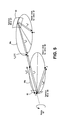
- FIG. 5 illustrates the geometry for a pair of non-co-planar spherical reflectors in accordance with another embodiment of the present invention, where, for simplicity, the second reflector is shown prior to being rotated 90° about axis A-B to provide a three dimensional imaging capability.
- f s is positive for 45° ⁇ 90°, so that the reflected sagittal rays are convergent, forming a real image in front of the minor, and negative for 0° ⁇ 45°, meaning that the reflected sagittal rays are divergent and form a virtual image behind the mirror.
- f s ⁇ , so that the reflected sagittal rays are parallel.
- Equation (5) the condition of equation (5) can be inferred from FIG. 2 a and ensures that the two real meridional images and the real and virtual sagittal images formed by the two crystals 20 , 22 appear at the same locations, so that the meridional and sagittal rays reflected from the two crystals have the same angles of convergence and divergence, respectively.
- FIG. 3 and FIG. 4 Two additional embodiments of the present invention, shown in FIG. 3 and FIG. 4 , which may be employed for the diagnosis of laser-produced plasmas, the imaging of biological samples, using the highly monochromatic radiation from synchrotron light sources, and for lithography with EUV radiation.
- A is the wavelength of the incident rays
- d 1 , d 2 and ⁇ 1 , ⁇ 2 are the 2d-spacings and Bragg angles for the two crystals or the two multilayer structures respectively.
- one of the Bragg angles is smaller and the other larger than 45°, e.g., ⁇ 1 ⁇ 45° and ⁇ 2 >45°.
- the sagittal image produced by reflector 62 is real, whereas the sagittal image obtained from reflector 60 is a virtual image F s , meaning that the sagittal rays reflected by reflector 60 are divergent and appear to emanate from a virtual focus behind the reflector.
- the two reflectors 40 , 42 and the corresponding Rowland circles 44 and 46 are arranged around a central circle 48 with the radius RT, such that the rays between the two reflectors are tangent to this circle.
- the centers of this central circle 48 and the two reflector spheres must be at the same point, O, which is also the origin of the x,y-coordinate system, shown in FIG. 3 .
- the size of the two reflectors 40 , 42 is largely exaggerated to depict the Johann error, which is the deviation of the edge rays 50 and 52 from the central circle 48 with radius RT at the point Q, where the central ray 54 is tangent to this circle. As shown in FIG. 3 , the Johann error is exactly the same for both reflectors. We also infer from FIG.
- f 1 s - R 1 ⁇ sin ⁇ ( ⁇ 1 ) cos ⁇ ( 2 ⁇ ⁇ ⁇ 1 ) is the distance of the sagittal focus F 1 s from the center C 1 of reflector 40 . Inserting this expression for f 1 s into eq. (6), one obtains
- ⁇ 1 - R 1 ⁇ cos ⁇ ( ⁇ 1 ) cos ⁇ ( 2 ⁇ ⁇ ⁇ 1 ) ( 14 ) and by analogy
- M H R 1 ⁇ cos ⁇ ( ⁇ 1 ) ⁇ cos ⁇ ( 2 ⁇ ⁇ ⁇ 2 )
- R 2 ⁇ cos ⁇ ( ⁇ 2 ) ⁇ cos ⁇ ( 2 ⁇ ⁇ ⁇ 1 ) cos ⁇ ( 2 ⁇ ⁇ ⁇ 2 ) cos ⁇ ( 2 ⁇ ⁇ ⁇ 1 ) , ( 16 )
- equation (9) In order to find the magnification, M V , in the direction vertical to the drawing plane of FIG. 3 , we imagine that the two reflectors are decoupled from each other and that the sagittal image, F 1 s , represents the image of an equivalent source, of at least the size of the Johann error, at the point Q.
- the magnification is therefore uniform and isotropic, i.e., independent of the direction, so that one obtains a magnified, undistorted image in all directions.
- This uniform magnification depends only on the Bragg angles ⁇ 1 and ⁇ 2 and is variable over a wide range.
- the magnification can be large if the Bragg angle ⁇ 1 is near 45°. We point out that in a real experimental setup, the reflector dimensions are much smaller than shown in FIG.
- This imaging scheme may be employed for the x-ray imaging of biological samples, using the highly monochromatic radiation at synchrotron light sources. It also has an important application in EUV lithography, where it offers considerable simplifications or advantages over the presently used systems, if the spherically bent reflectors are replaced by appropriate spherical multilayer reflectors. For this application the mask would be placed at F 1 s , in order to obtain a de-magnified image at F 2 s .
- the de-magnification can be selected by choosing appropriate values for the Bragg angles ⁇ 1 and ⁇ 2 .
- the main advantages for an application of this scheme to EUV lithography would be due to the fact that it provides non-astigmatic images with uniform and isotropic de-magnification and that only two reflectors are needed after the mask. It may also be important that with this scheme a two-dimensional image of the mask could be produced at once, so that a scanning process is not needed.
- FIG. 4 The imaging scheme, which is associated with case II, where in addition to the conditions of equations (8) and (9) also the conditions of equations (10) and (11) must be satisfied, is shown in FIG. 4 and is discussed below.
- This arrangement is shown in FIGS. 2 a and 2 b , where we stated that only the variant shown in FIG. 2 b is usable for x rays.
- the Bragg conditions on both crystals
- This latter statement must now be replaced by the more general condition of equation (11), which offers a much wider choice of Bragg angle combinations for this imaging scheme.
- a double-crystal spectrometer 58 which is associated with case II and satisfies the requirements of equations (8)-(11).
- the spectrometer 58 design is shown in FIG. 4 and is intended to be used for the observation of the spectra of helium-like argon in the wavelength range from 3.9494 ⁇ to 3.9944 ⁇ , which includes the helium-like lines w, x, y, and z and the associated dielectronic and inner-shell excited lithium-like satellites.
- the spectrometer 58 consists of two spherically bent crystals: a Highly Ordered Pyrolytic Graphite (HOPG) crystal 60 with a 2d-spacing of 6.702 ⁇ and a 110-quartz crystal 62 with a 2d-spacing 4.91304 ⁇ .
- the HOPG crystal 60 is a mosaic crystal with a mosaic spread that may vary between 0.4° and 0.8°. This crystal has a high reflectivity and a coarse spectral resolution. It is therefore used as the first crystal, which is irradiated by the source S.
- the 110-quartz crystal 62 has a high intrinsic resolution of 50 ⁇ rad rocking curve width and is used as the second crystal.
- the points S and I denote the positions of a point source and its image, respectively.
- F s is the central point of the virtual sagittal line image, produced of a source at S by the first crystal 60 , as well as the central point of the real sagittal line image that would be produced by the second crystal 62 of a source located at I.
- the symmetries of the ray pattern and the imaging properties of the meridional and sagittal rays can best be visualized by two rotations of the triangle IF s C 2 .
- the first rotation of the triangle is executed in the drawing plane of FIG. 4 about a vertical axis through the point O.
- the second (subsequent) rotation of the triangle is then executed about an axis in the drawing plane of FIG. 4 , which passes through the points I′, O, and F s ′, where I′, and F s ′ are the new positions of I, and F s , respectively, after the first rotation.
- the points C 1 and C 2 slide along the crystal surfaces to new positions “P 1 ” and “P 2 ”, and the point Q slides on the circumference of the central circle with radius RT. Also, the line C 1 C 2 is transformed into the line P 1 P 2 , which are both tangential to the central circle with radius RT—see FIG. 4 .
- the points C 2 and C 1 (and P 1 and P 2 ) remain on the crystal surfaces and move to new positions above or below the drawing plane of FIG. 4 , such that the elevated lines of the triangles represent the sagittal rays. Since the points “P 1 ” and “P 2 ” are reached from the points C 1 and C 2 by a rigid rotation of the triangle, it is clear that the widths W 1 and W 2 of the two crystals are related by
- H 2 H 1 f 2 s ⁇ f 1 s ⁇ ( 22 )
- the magnification M V of the imaging scheme in a direction perpendicular to the drawing plane is obtained by considering a rotation of the ray pattern about the y-axis, whereby the points I and S are moved in opposite directions to positions above and below the drawing plane, so that
- the first arrangement consists of two crystal (or reflector) pairs in series, where a reflector pair as shown in FIG. 2 and FIG. 4 is followed by a similar reflector pair that uses the image from the first reflector pair as the source. Since the image obtained from the first reflector pair is produced by rays that form a circular cone, the plane of the second reflector pair—which uses the rays emanating form the image of the first reflector pair as input—can be rotated about the axis of this circular cone by an arbitrary angle.
- the second arrangement consists of only two reflectors (instead of two reflector pairs in series), where the planes of the two Rowland circles are rotated by 90° to one another.
- This scheme which is shown in FIG. 5 , is not applicable to x-rays and EUV radiation, since the Bragg conditions cannot be simultaneously fulfilled on both reflectors.
- FIG. 5 illustrates the geometry of the embodiment of the invention.
- a fan of meridional rays originating from point P lies in the plane of the first Rowland circle 66 a of the first mirror 66 .
- the image is formed at point P′ which lies on the second Rowland circle 68 a of the second mirror 68 .
- the configuration of the first and second minors 66 and 68 in FIG. 5 is illustrated before the second minor 68 is rotated 90° about the axis A-B.
- Meridional rays from the object P on the Rowland circle 66 a of spherical mirror 66 are focused to point F m1 (P) which is also located on the Rowland circle 66 a .
- the point F m1 (P) lies at the sagittal focal point of the second mirror 68 , thereby ensuring point-to-point focusing of meridional rays from the object P.
- Equations 25 and 28 define the relationships among the minor's focal lengths that ensure point-to-point imaging in a configuration with perpendicular Rowland circles.
- the present invention contemplates electromagnetic or extreme ultraviolet imaging using a pair of spherically bent reflectors where the respective Rowland circles of the reflectors are arranged either co-planar to provide two dimensional point-to-point imaging or non-co-planar to provide three dimensional point-to-point imaging. Both approaches provide high quality imaging even at large angles of incidence without astigmatism. In the non-co-planar embodiments the planes of the two Rowland circles can be rotated to virtually any angle.
- Pairs of reflectors which may be minors or crystals, may be arranged in series, since the image of a point source obtained from a pair of spherical reflectors is formed by a circular cone of rays, so that the plane of the Rowland circles of the following reflector pair can be rotated about the axis of this cone by an arbitrary angle. Therefore, by using plural crystal pairs in series in accordance with this invention, it is possible to establish almost any light path and still obtain the benefit of non-astigmatic point-to-point imaging.
Landscapes
- Physics & Mathematics (AREA)
- Engineering & Computer Science (AREA)
- Spectroscopy & Molecular Physics (AREA)
- Chemical & Material Sciences (AREA)
- General Physics & Mathematics (AREA)
- Nanotechnology (AREA)
- High Energy & Nuclear Physics (AREA)
- General Engineering & Computer Science (AREA)
- Pathology (AREA)
- Immunology (AREA)
- General Health & Medical Sciences (AREA)
- Biochemistry (AREA)
- Analytical Chemistry (AREA)
- Life Sciences & Earth Sciences (AREA)
- Health & Medical Sciences (AREA)
- Mathematical Physics (AREA)
- Theoretical Computer Science (AREA)
- Crystallography & Structural Chemistry (AREA)
- Acoustics & Sound (AREA)
- Analysing Materials By The Use Of Radiation (AREA)
Abstract
Description
−R 1 cos(θ1)·tan(2θ1)=R 2 cos(θ2)·tan(2θ2)
from the spherically
f s 1 =f m 1 +f m 2 +|f s 2| (5)
where |fs 2| must be used, since fs 2<0. The condition of equation (5) can be inferred from
−R 1 cos(θ1)·tan(2θ1)=R 2 cos(θ2)·tan(2θ2) (6)
λ=2d 1 sin(θ1)=2 d 2 sin(θ2) (8)
must be simultaneously fulfilled on both reflectors of a crystal pair of a pair of multilayer structures, respectively. Here, A is the wavelength of the incident rays, and d1, d2 and θ1, θ2 are the 2d-spacings and Bragg angles for the two crystals or the two multilayer structures respectively. This condition leads to a specific experimental arrangement, where the two spherically bent reflectors, with their Rowland circles, are grouped around a central circle with the radius equal to
RT=R 1 cos(θ1)=R 2 cos(θ2) (9)
such that the incident and reflected rays for both reflectors are tangent to this circle. Here, the center of the circle with radius RT and the centers of the two reflector spheres with radii R1 and R2 must be at the same point. This experimental arrangement is common to the two schemes described below and shown in
R 1 cos(θ1)·tan(2θ1)=−R 2 cos(θ2)·tan(2θ2) (10)
which was already given as equation (6) above, must be satisfied for the rays between the two reflectors. Equation (10) is evidently different from equation (9). However, both conditions can be satisfied if
θ1+θ2=90° (11)
since then tan(2θ1)=−tan(2θ2).
ρ1 can be determined from the relation
ρ1 +R 1 cos(θ1)=f 1 s sin(2θ1), (13)
which is obtained from
is the distance of the sagittal focus F1 s from the center C1 of
and by analogy
so that the horizontal magnification MH is given by
where we have used equation (9). In order to find the magnification, MV, in the direction vertical to the drawing plane of
where x1 and x2 are the x-coordinates of the points F1 s and F2 s, respectively. Since the points F1 s and F2 s lie on the same line through the point O, at the distances ρ1 and ρ2 from O, it follows that the ratio of the x-coordinates must be equal to the ratio of ρ1 and ρ2, so that
The magnification is therefore uniform and isotropic, i.e., independent of the direction, so that one obtains a magnified, undistorted image in all directions. This uniform magnification depends only on the Bragg angles θ1 and θ2 and is variable over a wide range. The magnification can be large if the Bragg angle θ1 is near 45°. We point out that in a real experimental setup, the reflector dimensions are much smaller than shown in
λ*=2d 1 sin(θ1*)=2d 2 sin(θ2*)=2d 2 sin(90°−θ1*) (19)
leading to
so that equation (19) and equation (20) yield the values: λ*=3.9624 Å, θ1*=36.244°, and θ2*=53.756°, for which the
| TABLE 1 | ||
| θ1 | θ2 | |
| λw = 3.9494 Å | 36.106° | 53.500° |
| λ* = 3.9624 Å | 36.244° | 53.756° |
| λz = 3.9944 Å | 36.584° | 54.392° |
where the last equation on the RHS of equation (13) follows from equations (9), (11), and (20).
where
represents the distance of the sagittal focus Fs from C1 and C2, respectively. Using again equations (9), (11), and (21), one obtains
The magnification MV of the imaging scheme in a direction perpendicular to the drawing plane is obtained by considering a rotation of the ray pattern about the y-axis, whereby the points I and S are moved in opposite directions to positions above and below the drawing plane, so that
where x1 and x2 are the abscissas of points S and I, respectively, and where we have again used equation (11).
d=f m1 +f s2 (25)
which ensures that the focal point Fm1(P) is located at a distance fs2 from the
f s2 −f s1 =f m2 −f m1 (28)
Claims (7)
RT=R 1 cos(θ1)=R 2 cos(θ2)
RT=R 1 cos(θ1)=R 2 cos(θ2).
f s1 =f m1 +f m2 +|f s2|
RT=R 1 cos(θ1)=R 2 cos(θ2),
−R 1 cos(θ1)·tan(2θ1)=R 2 cos(θ2)·tan(2θ2)
Priority Applications (1)
| Application Number | Priority Date | Filing Date | Title |
|---|---|---|---|
| US12/436,708 US8217353B1 (en) | 2009-05-06 | 2009-05-06 | Non-astigmatic imaging with matched pairs of spherically bent reflectors |
Applications Claiming Priority (1)
| Application Number | Priority Date | Filing Date | Title |
|---|---|---|---|
| US12/436,708 US8217353B1 (en) | 2009-05-06 | 2009-05-06 | Non-astigmatic imaging with matched pairs of spherically bent reflectors |
Publications (1)
| Publication Number | Publication Date |
|---|---|
| US8217353B1 true US8217353B1 (en) | 2012-07-10 |
Family
ID=46395897
Family Applications (1)
| Application Number | Title | Priority Date | Filing Date |
|---|---|---|---|
| US12/436,708 Expired - Fee Related US8217353B1 (en) | 2009-05-06 | 2009-05-06 | Non-astigmatic imaging with matched pairs of spherically bent reflectors |
Country Status (1)
| Country | Link |
|---|---|
| US (1) | US8217353B1 (en) |
Cited By (5)
| Publication number | Priority date | Publication date | Assignee | Title |
|---|---|---|---|---|
| US20150055755A1 (en) * | 2013-08-21 | 2015-02-26 | The Trustees Of Princeton University | Novel Objective for EUV Microscopy, EUV Lithography, and X-Ray Imaging |
| CN104596466A (en) * | 2015-02-04 | 2015-05-06 | 厦门大学 | Splicing measurement method for two sections of profiles of large-caliber optical aspheric element |
| US10677744B1 (en) * | 2016-06-03 | 2020-06-09 | U.S. Department Of Energy | Multi-cone x-ray imaging Bragg crystal spectrometer |
| CN111678600A (en) * | 2020-08-10 | 2020-09-18 | 中国工程物理研究院激光聚变研究中心 | A flat-response Hall crystal |
| CN112259262A (en) * | 2020-11-05 | 2021-01-22 | 重庆邮电大学 | X-ray diffraction imaging double-crystal spectrometer |
Citations (6)
| Publication number | Priority date | Publication date | Assignee | Title |
|---|---|---|---|---|
| US3624395A (en) * | 1968-12-12 | 1971-11-30 | Siemens Ag | Arrangement for compensating a hyperbolic dependency of the amplitude of voltage pulses produced in a detector for x-ray quanta |
| US5016265A (en) * | 1985-08-15 | 1991-05-14 | The United States Of America As Represented By The Administrator Of The National Aeronautics And Space Administration | Variable magnification variable dispersion glancing incidence imaging x-ray spectroscopic telescope |
| US5026131A (en) * | 1988-02-22 | 1991-06-25 | Physical Optics Corporation | High channel density, broad bandwidth wavelength division multiplexer with highly non-uniform Bragg-Littrow holographic grating |
| US5581639A (en) * | 1995-05-04 | 1996-12-03 | National Research Council Of Canada | Raman-nath diffraction grating |
| US6259763B1 (en) * | 1999-05-21 | 2001-07-10 | The United States Of America As Represented By The United States Department Of Energy | X-ray imaging crystal spectrometer for extended X-ray sources |
| US20090225947A1 (en) * | 2005-08-01 | 2009-09-10 | X-Ray Optical Systems, Inc. | X-ray imaging systems employing point-focusing, curved monochromating optics |
-
2009
- 2009-05-06 US US12/436,708 patent/US8217353B1/en not_active Expired - Fee Related
Patent Citations (6)
| Publication number | Priority date | Publication date | Assignee | Title |
|---|---|---|---|---|
| US3624395A (en) * | 1968-12-12 | 1971-11-30 | Siemens Ag | Arrangement for compensating a hyperbolic dependency of the amplitude of voltage pulses produced in a detector for x-ray quanta |
| US5016265A (en) * | 1985-08-15 | 1991-05-14 | The United States Of America As Represented By The Administrator Of The National Aeronautics And Space Administration | Variable magnification variable dispersion glancing incidence imaging x-ray spectroscopic telescope |
| US5026131A (en) * | 1988-02-22 | 1991-06-25 | Physical Optics Corporation | High channel density, broad bandwidth wavelength division multiplexer with highly non-uniform Bragg-Littrow holographic grating |
| US5581639A (en) * | 1995-05-04 | 1996-12-03 | National Research Council Of Canada | Raman-nath diffraction grating |
| US6259763B1 (en) * | 1999-05-21 | 2001-07-10 | The United States Of America As Represented By The United States Department Of Energy | X-ray imaging crystal spectrometer for extended X-ray sources |
| US20090225947A1 (en) * | 2005-08-01 | 2009-09-10 | X-Ray Optical Systems, Inc. | X-ray imaging systems employing point-focusing, curved monochromating optics |
Non-Patent Citations (3)
| Title |
|---|
| Bergmann et al., "High-resolution X-ray imaging using Rowland-circle Bragg optics," 2002, IEEE Nuclear Science Symposium Conference Record, vol. 3, pp. 1481-1483. * |
| Bitter et al., "Wide-angle point-to-point x-ray imaging with almost arbitrarily large angles of incidence," 2008, Review of Scientific Instruments, vol. 79, pp. 10E927-1 to 10E927-3. * |
| Wittry et al., "X-ray optics of diffractors curved to a logarithmic spiral," 1993, Journal of Applied Physics, Volo. 74, pp. 3534-3540. * |
Cited By (6)
| Publication number | Priority date | Publication date | Assignee | Title |
|---|---|---|---|---|
| US20150055755A1 (en) * | 2013-08-21 | 2015-02-26 | The Trustees Of Princeton University | Novel Objective for EUV Microscopy, EUV Lithography, and X-Ray Imaging |
| US9329487B2 (en) * | 2013-08-21 | 2016-05-03 | Manfred Bitter | Objective for EUV microscopy, EUV lithography, and x-ray imaging |
| CN104596466A (en) * | 2015-02-04 | 2015-05-06 | 厦门大学 | Splicing measurement method for two sections of profiles of large-caliber optical aspheric element |
| US10677744B1 (en) * | 2016-06-03 | 2020-06-09 | U.S. Department Of Energy | Multi-cone x-ray imaging Bragg crystal spectrometer |
| CN111678600A (en) * | 2020-08-10 | 2020-09-18 | 中国工程物理研究院激光聚变研究中心 | A flat-response Hall crystal |
| CN112259262A (en) * | 2020-11-05 | 2021-01-22 | 重庆邮电大学 | X-ray diffraction imaging double-crystal spectrometer |
Similar Documents
| Publication | Publication Date | Title |
|---|---|---|
| JP6478433B2 (en) | X-ray microscope | |
| Pikuz et al. | Bragg X-ray optics for imaging spectroscopy of plasma microsources | |
| Casalbuoni et al. | Far-infrared transition and diffraction radiation | |
| WO1992008235A1 (en) | Device for controlling beams of particles, x-ray and gamma quanta and uses thereof | |
| US8217353B1 (en) | Non-astigmatic imaging with matched pairs of spherically bent reflectors | |
| WO2015093944A1 (en) | Spectrometer for generating a two dimensional spectrum | |
| CN106802428A (en) | A kind of x-ray imaging detector of radiation hardness and high heat load | |
| Salmaso et al. | BEaTriX (Beam Expander Testing X-ray facility) for testing ATHENA's SPO modules: advancement status | |
| Pareschi et al. | X-ray telescopes based on Wolter-I optics | |
| Wu et al. | Wolter mirrors for neutron imaging | |
| US20210247334A1 (en) | X-ray mirror optics with multiple hyperboloidal / hyperbolic surface profiles | |
| Stoupin et al. | The multi-optics high-resolution absorption x-ray spectrometer (HiRAXS) for studies of materials under extreme conditions | |
| US20250093770A1 (en) | Illumination optical unit for a mask inspection system | |
| US20050226372A1 (en) | X-ray image magnifying device | |
| Hoover et al. | Design of an imaging microscope for soft X-ray applications | |
| Vishnyakov et al. | High-aperture monochromator-reflectometer and its usefulness for CCD calibration | |
| Lemaire et al. | Space telescopes | |
| Bitter et al. | Wide-angle point-to-point x-ray imaging with almost arbitrarily large angles of incidence | |
| Ragozin et al. | Stigmatic high-resolution high-throughput narrow-band diffraction spectrograph employing X-ray multilayer mirrors | |
| Dogadin et al. | Design of a soft X-ray and extreme UV reflectometer equipped with a high-resolution monochromator and high-brightness laser-plasma radiation source | |
| Bitter et al. | Non-astigmatic imaging with matched pairs of spherically bent crystals or reflectors | |
| Perekalov et al. | Microscope for investigating the size of an EUV radiation source emitting at 11.2 nm | |
| Li et al. | A sagittally confined high-resolution spectrometer in thewater window' | |
| Flora et al. | Novel portable high-luminosity monochromatically tunable x-ray microscope | |
| JP7751307B2 (en) | X-ray optical device |
Legal Events
| Date | Code | Title | Description |
|---|---|---|---|
| AS | Assignment |
Owner name: ENERGY, UNITED STATES DEPARTMENT OF, DISTRICT OF C Free format text: CONFIRMATORY LICENSE;ASSIGNORS:BITTER, MANFRED LUDWIG;HILL, KENNETH WAYNE;SCOTT, STEVEN DOUGLAS;AND OTHERS;SIGNING DATES FROM 20090608 TO 20090612;REEL/FRAME:023361/0331 |
|
| STCF | Information on status: patent grant |
Free format text: PATENTED CASE |
|
| FPAY | Fee payment |
Year of fee payment: 4 |
|
| FEPP | Fee payment procedure |
Free format text: MAINTENANCE FEE REMINDER MAILED (ORIGINAL EVENT CODE: REM.); ENTITY STATUS OF PATENT OWNER: LARGE ENTITY |
|
| LAPS | Lapse for failure to pay maintenance fees |
Free format text: PATENT EXPIRED FOR FAILURE TO PAY MAINTENANCE FEES (ORIGINAL EVENT CODE: EXP.); ENTITY STATUS OF PATENT OWNER: LARGE ENTITY |
|
| STCH | Information on status: patent discontinuation |
Free format text: PATENT EXPIRED DUE TO NONPAYMENT OF MAINTENANCE FEES UNDER 37 CFR 1.362 |
|
| FP | Expired due to failure to pay maintenance fee |
Effective date: 20200710 |