US8215720B2 - Spoke wheel assembled without tension or compression - Google Patents
Spoke wheel assembled without tension or compression Download PDFInfo
- Publication number
- US8215720B2 US8215720B2 US12/300,554 US30055407A US8215720B2 US 8215720 B2 US8215720 B2 US 8215720B2 US 30055407 A US30055407 A US 30055407A US 8215720 B2 US8215720 B2 US 8215720B2
- Authority
- US
- United States
- Prior art keywords
- spokes
- rim
- hub
- spoke
- wheel
- Prior art date
- Legal status (The legal status is an assumption and is not a legal conclusion. Google has not performed a legal analysis and makes no representation as to the accuracy of the status listed.)
- Expired - Fee Related, expires
Links
Images


Classifications
-
- B—PERFORMING OPERATIONS; TRANSPORTING
- B60—VEHICLES IN GENERAL
- B60B—VEHICLE WHEELS; CASTORS; AXLES FOR WHEELS OR CASTORS; INCREASING WHEEL ADHESION
- B60B1/00—Spoked wheels; Spokes thereof
- B60B1/06—Wheels with compression spokes
- B60B1/14—Attaching spokes to rim or hub
-
- B—PERFORMING OPERATIONS; TRANSPORTING
- B60—VEHICLES IN GENERAL
- B60B—VEHICLE WHEELS; CASTORS; AXLES FOR WHEELS OR CASTORS; INCREASING WHEEL ADHESION
- B60B1/00—Spoked wheels; Spokes thereof
- B60B1/003—Spoked wheels; Spokes thereof specially adapted for bicycles
-
- B—PERFORMING OPERATIONS; TRANSPORTING
- B60—VEHICLES IN GENERAL
- B60B—VEHICLE WHEELS; CASTORS; AXLES FOR WHEELS OR CASTORS; INCREASING WHEEL ADHESION
- B60B1/00—Spoked wheels; Spokes thereof
- B60B1/02—Wheels with wire or other tension spokes
- B60B1/0253—Wheels with wire or other tension spokes the spoke being hollow
-
- B—PERFORMING OPERATIONS; TRANSPORTING
- B60—VEHICLES IN GENERAL
- B60B—VEHICLE WHEELS; CASTORS; AXLES FOR WHEELS OR CASTORS; INCREASING WHEEL ADHESION
- B60B1/00—Spoked wheels; Spokes thereof
- B60B1/02—Wheels with wire or other tension spokes
- B60B1/0261—Wheels with wire or other tension spokes characterised by spoke form
- B60B1/0284—Wheels with wire or other tension spokes characterised by spoke form the spoke being threaded at both ends
-
- B—PERFORMING OPERATIONS; TRANSPORTING
- B60—VEHICLES IN GENERAL
- B60B—VEHICLE WHEELS; CASTORS; AXLES FOR WHEELS OR CASTORS; INCREASING WHEEL ADHESION
- B60B1/00—Spoked wheels; Spokes thereof
- B60B1/02—Wheels with wire or other tension spokes
- B60B1/04—Attaching spokes to rim or hub
- B60B1/041—Attaching spokes to rim or hub of bicycle wheels
-
- B—PERFORMING OPERATIONS; TRANSPORTING
- B60—VEHICLES IN GENERAL
- B60B—VEHICLE WHEELS; CASTORS; AXLES FOR WHEELS OR CASTORS; INCREASING WHEEL ADHESION
- B60B1/00—Spoked wheels; Spokes thereof
- B60B1/02—Wheels with wire or other tension spokes
- B60B1/04—Attaching spokes to rim or hub
- B60B1/042—Attaching spokes to hub
-
- B—PERFORMING OPERATIONS; TRANSPORTING
- B60—VEHICLES IN GENERAL
- B60B—VEHICLE WHEELS; CASTORS; AXLES FOR WHEELS OR CASTORS; INCREASING WHEEL ADHESION
- B60B1/00—Spoked wheels; Spokes thereof
- B60B1/02—Wheels with wire or other tension spokes
- B60B1/04—Attaching spokes to rim or hub
- B60B1/043—Attaching spokes to rim
- B60B1/044—Attaching spokes to rim by the use of spoke nipples
- B60B1/045—Attaching spokes to rim by the use of spoke nipples characterised by their specific shape
-
- B—PERFORMING OPERATIONS; TRANSPORTING
- B60—VEHICLES IN GENERAL
- B60B—VEHICLE WHEELS; CASTORS; AXLES FOR WHEELS OR CASTORS; INCREASING WHEEL ADHESION
- B60B1/00—Spoked wheels; Spokes thereof
- B60B1/02—Wheels with wire or other tension spokes
- B60B1/04—Attaching spokes to rim or hub
- B60B1/043—Attaching spokes to rim
- B60B1/048—Attaching spokes to rim by the use of screws
-
- B—PERFORMING OPERATIONS; TRANSPORTING
- B60—VEHICLES IN GENERAL
- B60B—VEHICLE WHEELS; CASTORS; AXLES FOR WHEELS OR CASTORS; INCREASING WHEEL ADHESION
- B60B21/00—Rims
- B60B21/02—Rims characterised by transverse section
- B60B21/025—Rims characterised by transverse section the transverse section being hollow
-
- B—PERFORMING OPERATIONS; TRANSPORTING
- B60—VEHICLES IN GENERAL
- B60B—VEHICLE WHEELS; CASTORS; AXLES FOR WHEELS OR CASTORS; INCREASING WHEEL ADHESION
- B60B21/00—Rims
- B60B21/06—Rims characterised by means for attaching spokes, i.e. spoke seats
- B60B21/062—Rims characterised by means for attaching spokes, i.e. spoke seats for bicycles
-
- B—PERFORMING OPERATIONS; TRANSPORTING
- B60—VEHICLES IN GENERAL
- B60B—VEHICLE WHEELS; CASTORS; AXLES FOR WHEELS OR CASTORS; INCREASING WHEEL ADHESION
- B60B21/00—Rims
- B60B21/06—Rims characterised by means for attaching spokes, i.e. spoke seats
- B60B21/064—Rims characterised by means for attaching spokes, i.e. spoke seats characterised by shape of spoke mounting holes, e.g. elliptical or triangular
-
- B—PERFORMING OPERATIONS; TRANSPORTING
- B60—VEHICLES IN GENERAL
- B60B—VEHICLE WHEELS; CASTORS; AXLES FOR WHEELS OR CASTORS; INCREASING WHEEL ADHESION
- B60B27/00—Hubs
- B60B27/0005—Hubs with ball bearings
-
- B—PERFORMING OPERATIONS; TRANSPORTING
- B60—VEHICLES IN GENERAL
- B60B—VEHICLE WHEELS; CASTORS; AXLES FOR WHEELS OR CASTORS; INCREASING WHEEL ADHESION
- B60B27/00—Hubs
- B60B27/02—Hubs adapted to be rotatably arranged on axle
- B60B27/023—Hubs adapted to be rotatably arranged on axle specially adapted for bicycles
-
- Y—GENERAL TAGGING OF NEW TECHNOLOGICAL DEVELOPMENTS; GENERAL TAGGING OF CROSS-SECTIONAL TECHNOLOGIES SPANNING OVER SEVERAL SECTIONS OF THE IPC; TECHNICAL SUBJECTS COVERED BY FORMER USPC CROSS-REFERENCE ART COLLECTIONS [XRACs] AND DIGESTS
- Y10—TECHNICAL SUBJECTS COVERED BY FORMER USPC
- Y10T—TECHNICAL SUBJECTS COVERED BY FORMER US CLASSIFICATION
- Y10T29/00—Metal working
- Y10T29/49—Method of mechanical manufacture
- Y10T29/49481—Wheel making
- Y10T29/49492—Land wheel
- Y10T29/49513—Compression, e.g., nontension, spoke type wheel making
- Y10T29/49515—Joining spokes to rim and hub
Definitions
- the invention relates to a new design of a compression spoke wheel, in particular a cycle wheel.
- the invention also relates to a compression spoke wheel having at least one such compression spoke, as well as a rolling apparatus, in particular a cycle, equipped with at least one such wheel.
- the wheel has existed since the mists of time.
- the first wheels were solid wheels.
- a first improvement consisted in building compression spoke wheels, which were lighter. The spokes of such wheels were biased in compression and in flexion by a rim. Then, the wheel was ringed by a metal hoop and the compression spokes were pre-stressed in compression.
- the patent document CH 91759 describes such a mode of construction.
- the invention of the tension wire spoke wheel goes back to around 1866, and is credited to Euffer Meyer. This invention made it possible to build wheels with spokes having a considerably decreased cross section, resulting in a substantial weight reduction. It also became possible to increase the wheel diameter, and therefore to increase its size, as was the case with the steel high-wheels whose pedals were in direct engagement with the driving wheel.
- the terms “traction” and “tension” are used interchangeably herein to describe a spoke having a positive tension.
- a currently available spoke wheel includes a peripheral rim provided to receive a tire, a central hub, and connecting spokes between the rim and the hub.
- the number of spokes is variable depending upon the type of wheels; it generally varies between twelve and forty.
- the spokes are distributed in two sets, each of which connects the rim to a respective one of the ends of the hub.
- the spokes of each set form an angle with the median plane of the rim, which is commonly referred to as the dish angle.
- the spokes structurally connect the rim and the hub, which makes it possible to provide the wheel with good rigidity and good fatigue strength.
- the external loads to which a wheel is subjected during use can be divided into a radial force directed along the median plane of the rim, a lateral force directed perpendicular to this such plane, and a motive force or, conversely, a braking force tangent to the wheel circle, which corresponds to the transmission of torque between the hub and the rim.
- wheels other than tension spoke wheels currently exist.
- solid wheels or so-called compression spoke wheels are known, which are made out of composite material and are used mainly for their aerodynamic properties.
- the patent documents WO 2004/033231 and FR 2701899 describe such wheels.
- compression spoke wheels made of composite material, or of molded alloy
- the compression spokes are in a smaller number, about three to five compression spokes per wheel. Indeed, these spokes, which must withstand compressive forces, have a much larger cross section than the usual common spokes to avoid buckling, and their dimensions themselves do not allow a greater number of compression spokes to be used.
- the tension spoke wheel still offers the best compromise between lightness and strength, provided that it is well built and properly adjusted.
- the spoke tension produces compressive stresses in the rim body. It is estimated that for a road bike wheel having 36 spokes, with each spoke being tensioned to 1000 Newtons, the compressive force resulting in the area of the rim body is 5730 Newtons, which produces a compressive stress of 88 MegaPascals (MPa), which, for a material commonly used for a rim (aluminum 6106, for example), already represents 40% of the material inherent strength potential (220 MPa). In other words, this resultant compression already weakens the rim considerably.
- MPa MegaPascals
- the spoke tension is exerted on the rim locally.
- Each spoke via its tension, produces a local shearing force in the area of its attachment zone, as well a variable bending moment between each spoke hole.
- the bending moment leads to a polygonal deformation of the rim, commonly referred to as a “jump”, with a local lateral run-out or deformation in the area of each spoke attachment zone.
- EP 1316442 proposes to start with a rim that is pre-deformed in an opposite configuration (see FIG. 5 of this patent), which is difficult to implement.
- the spoked wheel is a wheel including a peripheral rim, a central hub, and individual connecting spokes between the rim and the hub, the spokes, in the free state, being assembled without tension or compression between the rim and the hub, and with each spoke being able to withstand a compression load of at least 60 decaNewtons (daN) without buckling.
- the wheel has a greater number of spokes than compression spoke wheels and comprises, for example, more than ten spokes.
- Such a construction has the advantage of reducing all of the stresses within the spokes of the rim to zero, in the free state. Consequently, the spokes are provided to be capable of withstanding a substantial compressive force, without buckling, in order to be able to withstand the forces being exerted in the wheel during use.
- lateral rigidity is almost constant, which is not true of wheels with three compression spokes, for example; and frontal rigidity is not too high and substantially constant, which provides the cyclist with a comfortable wheel with respect to frontal impacts due to the irregularities of the road.
- each spoke comprises a body having an outer diameter that is greater than 4.8 mm and an inner diameter that is less than 15 mm.
- the spokes therefore are tubular spokes, having a greater outer diameter. This makes it possible to increase the (buckling) strength upon compression of the spoke without increasing the weight thereof.
- Spokes having a non-tubular cross section, such as an I-shaped transverse cross section, for example, can also be used.
- Spokes according to the invention can have a non-constant cross section in the longitudinal direction, and the spoke can have a cross section having a variable shape along the longitudinal direction, such as, for example, a larger cross section in the median zone in order to withstand buckling more efficiently.
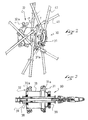
- FIG. 1 is a perspective view of a wheel incorporating the construction according to the invention
- FIG. 2 is a detailed view, on an enlarged scale, of the spoke assembly in the area of the hub,
- FIG. 3 is a longitudinal al view of the hub of FIG. 2 , without the spokes,
- FIGS. 4 and 5 are plan views of the wheel showing the various steps of assembling the spokes
- FIG. 6 is a detailed view, on an enlarged scale, of FIG. 5 , showing the spoke assembly in the area of the hub,
- FIG. 7 is a al view along the line VII-VII of FIG. 5 showing the attachment of the spokes in the area of the rim,
- FIG. 8 is a al view along the line VIII-VIII of FIG. 6 .
- FIG. 9 is a view similar to FIG. 7 according to another embodiment.
- FIG. 10 is a view showing an example of binding two spokes
- FIG. 11 is a partial perspective view of a wheel according to another embodiment
- FIG. 12 is a cross-sectional view along the line XII-XII of FIG. 11 .
- FIG. 13 is a cross-sectional view along the line XIII-XIII of FIG. 11 .
- the wheel 1 conventionally includes a peripheral rim 20 , a central hub 30 , and connecting spokes 40 , 50 extending between the rim 20 and the hub 30 .
- the spokes 40 , 50 are distributed in two sets, each set of spokes 40 , 50 being attached to one end 31 , 32 , respectively, of the hub 30 , and extending from the end 31 , 32 , respectively, from the hub towards the rim 20 .
- the spokes 40 , 50 are attached to the rim 20 alternately with the spokes 50 , the spokes 40 , 50 being distributed evenly along the periphery of the rim. They can also be distributed, as known, on the various sets in predetermined groups on the tension spoke wheels, as described, for example, in U.S. Pat. No. 6,145,938.
- Each set of spokes 40 , 50 comprises ten in number, or a total of twenty, which is a much greater number than the number of compression spokes in a so-called compression spoke wheel, having a maximum of six compression spokes, and a smaller number than the usual number of spokes in a tension spoke wheel having about 12 to 40 spokes. This number of spokes can be reduced to 10 on both of the two sets.
- the rim 20 is of any appropriate type, and has, as shown for example in FIG. 7 , a hollow metal box-structure with an upper bridge 21 having a channel 21 a for receiving a tube at its periphery, a lower bridge 22 having threaded chimney-shape openings 22 a for attaching the spokes, and two side walls 23 , 24 connecting the two bridges.
- the threaded chimneys 22 a can be created by flow drilling, as described in the patent document FR 2 750 913.
- the box is further reinforced in each corner by a circular band 25 made of carbon, as described in the patent document FR 2 881 682.
- the rim can have a single bridge, a receiving channel 21 a that has a different shape and in particular is capable of receiving a tire.
- the spokes 40 , 50 in the free state (i.e., without a load on the wheel), are assembled without tension or compression between the rim 20 and the hub 30 , and each spoke can withstand a compressive load of at least 60 daN. That is, the spokes 40 , 50 can withstand a net load in compression, i.e., a compressive load minus any tensile load (zero in the invention), of at least 60 daN.
- each spoke 40 , 50 comprises, as shown in FIGS. 7 and 8 , an elongated body 40 a , 50 a , respectively, defining a longitudinal direction L for each spoke, and comprising two attachment ends 41 , 51 and 43 , 53 , respectively.
- the body 40 a , 50 a of each spoke is a tubular body having, for example, a circular or elliptical cross section, made of a material having high strength properties and, in particular, made of pultruded carbon.
- each spoke 40 , 50 has an outer diameter D that is greater than 4.8 mm, (5.5 mm, for example), i.e., no less than 4.8 mm, and an inner diameter d that is less than 15 mm (4.1 mm, for example) with a wall thickness of 0.7 mm, such wall thickness being capable of being decreased in the event of a (tubular) hollow spoke filled with foam, for example.
- Various values can also be obtained depending upon the materials and, for example, if HM (high modulus) carbon fibers having a modulus higher than 200 GPa are used.
- the spokes adapted to a wheel of this type are selected so that their EI characteristics are greater than 10 6 Nmm 2 , for a spoke having a normal length (which would in fact be equivalent to the EI value of a steel spoke 3.2 mm in diameter and therefore too heavy for use in a wheel, such steel spokes generally having a diameter of 2 mm).
- Such a spoke is sufficient to build a bicycle wheel with eighteen spokes that are not tensioned under normal conditions of use, the maximum force on each spoke then being less than 140 daN.
- a certain amount of spoke buckling is allowable under certain conditions, as long as any risk of rupture of the spoke is avoided.
- the product “E ⁇ I” is important to resistance to compression force.
- the wheel includes a device for the play-free connection, or bilateral connection, of at least one end of each spoke 40 , 50 to the rim or to the hub.
- the hub 30 comprises a tubular body 33 rotationally mounted by means of bearings 38 on a shaft 39 , adapted to receive the rotational axle of the wheel, and two ends 31 , 32 for attaching the spokes.
- Each end 31 , 32 generally has the shape of a disc or flange extending radially from the tubular body 33 .
- each of the flanges 31 , 32 are housings 31 a , 32 a , respectively, having a generally cylindrical shape and extending along a substantially tangent direction T with respect to the hub in the area of the end or flange 31 , 32 , respectively.
- the wheel can be said to have a tangent or semi-tangent spoke pattern, as known to those skilled in the art.
- spoke pattern as can be seen in FIGS. 1 and 6 , for example, each spoke crosses at least one other spoke that runs from the same flange of the hub.
- These housings 31 a , 32 a have an inner diameter corresponding substantially to the outer diameter D of the spokes 40 , 50 and are adapted to receive the spokes.
- each housing 31 a , 32 a has a length l of approximately 10 to 15 mm (see FIG. 6 ) in order to facilitate the assembly and, thereafter, the attachment of the spokes 40 , 50 .
- each end 31 , 32 comprises five pairs of housings 31 a , 32 a distributed evenly along the periphery of the hub.
- each spoke 40 , 50 is provided, at its end 41 , 51 adapted to be fixed to the rim 20 , with an end piece 42 , 52 provided with an external threading 42 a , 52 a , respectively, and fixed by an adhesive to the spoke end 41 , 51 , the latter being closed by means of a stopper, such as stopper 44 in spoke end 41 , in order to prevent the adhesive from penetrating within the tube constituting the spoke during the assembly operation on the spoke.
- Each threaded end 42 , 52 is adapted to cooperate with the associated threading of a chimney-shaped opening 22 a of the rim for fixing the end piece 42 , 52 of the spoke end to the rim by screw-threaded engagement. The other end of each spoke is free (see FIG. 8 ).
- the play-free device for each spoke 40 , 50 takes the form of glue for gluing a portion of the end 43 , 53 of each spoke in the area of the hub and, at the rim, a threaded engagement between its other end and the threaded end piece 42 , 52 . Therefore, the connection between the spoke and the rim and the connection between the spoke and the hub has no opportunity for “play,” i.e., no opportunity for movement in either direction along the length of the spoke relative to the rim and along the length of the spoke relative to the hub.
- Such a “play-free” connection can also be said to be a “bi-lateral” or “bi-direction” connection in this same sense, i.e., the connection does not allow movement, at the connection, in either direction along the length of the spoke, for example.
- This assembly is carried out as indicated more particularly in FIGS. 4 and 5 .
- the spokes 40 , 50 are prepared by cutting the tubes made of pultruded carbon fiber, of which they are formed, to the desired length and by assembling the end pieces 42 , 52 by gluing as previously indicated.
- This gluing is undertaken after preliminary degreasing of the surfaces for optimum adhesion.
- This gluing can also be improved by providing an appropriate surface condition (for example, roughness, grooves) within each end piece 42 , 52 , in order to improve the hold of the adhesive.
- each spoke is then inserted into an associated housing 31 a , 32 a , respectively, of the hub by placing a seal joint, for example an O-ring joint 43 a , 53 a , on the spoke, in the area of the outlet of the associated housing 31 a , 32 a (see FIG. 8 ).
- the spokes 40 , 50 of the same set can be assembled by pairs by means of a flexible band 80 (for example an O-ring seal or ring made out of synthetic material such as Delrin, Polyamide, or Acetate) in order to create a knot and to push back the buckling limits of each spoke in compression.
- the spokes can be prepared by pairs with their binding band 80 before assembly, as shown in FIG. 10 , in order to facilitate such assembly.
- the rim 20 is then positioned around the subassembly of the hub 30 and spokes 40 , 50 , as shown in FIG. 4 , these spokes being retracted within their respective housings 31 a , 32 a in order to enable the correct positioning of the rim around the subassembly, and each end piece 42 , 52 is then inserted and screwed into a chimney-shaped opening 22 a of the rim.
- Each housing 31 a , 32 a therefore constitutes an arrangement for retracting the spokes before final assembly, as well as for guiding and sliding the spokes during the assembly.
- the whole is positioned on an appropriate unit to guarantee a perfect geometry of the wheel and, in particular, the perpendicularity of the hub axis relative to the plane of the rim and the centering, and the jump of the hub relative to the rim.
- each spoke is then glued in the associated hub housing 31 a , 32 a , the joint 43 a , 53 a providing sealing at the time gluing is performed.
- each housing 31 a , 32 a has a cylindrical recess 35 whose diameter is greater than that of the spoke, and which is closed at one end by a shoulder 36 whose diameter is adjusted (play of about 1/100° mm) to that of the spoke 40 , 50 , and which opens out at the other end, in the area of the O-ring joint 43 a , 53 a .
- the adhesive is placed within the recess prior to the assembly of each spoke 40 , 50 .
- the small play in the area of the shoulder 36 allows some air to escape during the injection of the adhesive, but also makes it possible to retain the adhesive.
- the adhesive is inserted, after the spokes are positioned and fixed in the area of the rim, via a hole 70 having a conical shape, for example, arranged radially in each housing 31 a , 32 a , before the shoulder 36 , for example by means of a needle.
- the adhesive is then allowed to polymerize at room temperature, this solution being preferred if the rim is made of a different material (for example, metal) than the spokes, in order not to induce thermal dilatation of the materials, or in a drying oven at a temperature of about 80° C.
- the wheel is disassembled from the unit. If polymerization is allowed to occur at room temperature, an additional curing can possibly be performed in order to guarantee complete adhesion.
- the adhesive is for example a two-part epoxy resin, such as known under the trade name DP460.
- Another alternative assembly can be to screw to the maximum the tubes of the spokes 40 , 50 with the end pieces 42 , 52 glued beforehand in the rim 20 , and then to position the hub 30 in the middle and unscrew the end pieces 42 , 52 in order to cause the ends 41 , 51 of the spokes to penetrate in the gluing housings 31 a , 32 a of the hub; this solution requires a particularly long threading of each end piece 42 , 52 , because it is then unscrewed from the gluing length on the hub side.
- the threaded connection between the rim and the end piece 42 , 52 of each spoke must be bilateral in tension/compression, without play.
- a polyamide coating, of the “Nylock” type can be deposited as a device for neutralizing, i.e., eliminating, any play in the connection, i.e., the play of the threading 42 a , 52 a .
- the threading can be glued by means of an anaerobic or epoxy adhesive; the end piece can also be screwed home in the chimneys 22 a against a shoulder made on the end piece.
- Another alternative is the gluing of the carbon tube of the spoke directly in the chimney 22 a of the rim; the gluing length is shorter, but the weight of the insert is gained.
- the spoke can also be glued in an attached insert that is brazed as described in the patent document EP 1595721.
- the spoke can also be glued in a composite rim.
- FIGS. 11 to 13 illustrate another embodiment, in which similar elements are designated by the same reference numerals increased by 100 .
- the hub 130 is reduced to the bare and comprises only two flanges 131 rotatably mounted on a shaft 139 of the hub by means of bearings 138 .
- the flanges 131 are identical in this case, and comprise substantially radial chimney-shaped openings 132 defining cylindrical housings 132 a for each spoke 140 , 150 , each chimney 132 forming an angle ⁇ of about 82.5° with respect to the longitudinal axis L of the hub.
- the flanges 131 of the hub are not connected to one another by a body, in contrast with the conventional hubs or to the hub of the preceding embodiment.
- the wheel can be said to have a radial spoke pattern.
- spoke pattern as can be seen in FIG. 11 , for example, each spoke extends from hub to rim without crossing another spoke that runs from the same flange of the hub.
- the spokes 140 , 150 are attached by gluing within the chimneys 132 of the flanges 131 after the relative positioning of the spokes/rim/hub according to the process described above.
- the spokes 140 , 150 are assembled prior to positioning the bearings 138 , so as to be capable of sliding in their housing 138 a during the assembly.
- Such a hub construction without body between the flanges 131 is made possible due to the elimination of any tension in the spokes 140 , 150 in the free state (non loaded state) of the wheel.
- a hub construction such as known, for example from U.S. Pat. No. 5,647,643, would not be viable.
- the spoke tension has the effect of producing an axial load of about 700 N between two opposite spoke sets; this force is taken up axially by the two bearings, which produces on each bearing a considerable friction torque that generates a loss of power that negatively affects the cyclist's performance; moreover, this substantial axial force damages the bearings very quickly.
- the elimination of the spoke tension according to the invention cancels this axial force completely and therefore makes this construction completely functional and possible.
- the assembly of the spokes on the rim side can be carried out as shown in FIG. 13 , i.e., in the same manner as shown in FIG. 7 , the only difference being that the spokes 140 , 150 are provided with an end piece 142 but do not include a stopper. A stopper can also be provided, however.
- the wheel can be very lightly axially pre-stressed in order to preload the bearings in one direction, and thus to cancel their radial play by a small axial pre-stressing.
- the thrust center (and substantially the center of the bearing) of the ball bearings 138 are located at the convergence point of the various spokes 140 , 150 . Indeed, by neglecting the effect of spoke bending and by considering only the axial component of the traction or compression, the resultant of the spoke set always passes through the convergence points of the spokes of the set. Therefore, the annular bearing works under good conditions, without any lateral torsional buckling moment.
- the spokes can have a cross section that is not necessarily tubular, for example, I-shaped, and/or a shape of evolution (for example, the shape of a “barrel”, with a median zone having a larger cross section), or the spokes can be made of a non-composite material, for example a metallic material.
- a shape of evolution for example, the shape of a “barrel”, with a median zone having a larger cross section
- the spokes can be made of a non-composite material, for example a metallic material.
- differential expansion of the rim with respect to the spokes (related to change in conditions caused by gluing), or the inflation of the tire or other factors (slight pre-stressing of the rim in its assembly by gluing), can produce slight tensile/compressive stresses in the spokes, without leaving the scope of the invention, these stresses being considered as minor and the spokes then still being assembled almost without tension or compression.
Abstract
Description
-
- the wheel no longer has any tension, the rupture of a spoke no longer producing any lateral run-out or deformation as in a tension or compression spoke wheel,
- the wheel no longer has any residual stresses; it is thus less biased and can therefore be made lighter,
- the spokes and their ends are much less biased in tension and are thus stronger, as are the rim and the hub,
- the wheel is more resistant to fatigue (less stress), the wheel no longer has any polygonal effect at all, or any induced lateral run-out,
- if a spoke is broken, it can be replaced by removing the old one and by attaching a spoke directly to the wheel, without any particular assembly.
M=LρS=L·ρ·π·(D 2−d2)/4
-
- L is the length of the spoke,
- ρ is the density of the material (g/mm3),
- D is the outer diameter (mm),
- d is the inner diameter (mm),
- S is the cross section of the spoke.
F=π 2 EI/(KL)2=π3(D 4 −d 4)E/[64(KL)2]
-
- with coefficient K being a function of the construction of the end connections,
- K=0.5 for embedded end/embedded end (i.e., each end of the spoke is embedded),
- K=1 for ball-joint end connection/ball-joint end connection,
- K=2 for embedded end/free end,
- K=4 for free end/free end,
- E is the Young's modulus of material in MPa,
- I is the quadratic moment (mm4)=π(D4−d4)/64 for a tubular cross section,
- L is the length of the beam (mm)(i.e., spoke) between supports.
Claims (25)
Applications Claiming Priority (3)
| Application Number | Priority Date | Filing Date | Title |
|---|---|---|---|
| FR0604237A FR2900869B1 (en) | 2006-05-12 | 2006-05-12 | SPOKE WHEEL |
| FR0604237 | 2006-05-12 | ||
| PCT/FR2007/000770 WO2007135260A1 (en) | 2006-05-12 | 2007-05-04 | Spoke wheel |
Publications (2)
| Publication Number | Publication Date |
|---|---|
| US20090160243A1 US20090160243A1 (en) | 2009-06-25 |
| US8215720B2 true US8215720B2 (en) | 2012-07-10 |
Family
ID=37714625
Family Applications (2)
| Application Number | Title | Priority Date | Filing Date |
|---|---|---|---|
| US12/300,554 Expired - Fee Related US8215720B2 (en) | 2006-05-12 | 2007-05-04 | Spoke wheel assembled without tension or compression |
| US12/300,585 Expired - Fee Related US8162407B2 (en) | 2006-05-12 | 2007-05-04 | Spoked wheel |
Family Applications After (1)
| Application Number | Title | Priority Date | Filing Date |
|---|---|---|---|
| US12/300,585 Expired - Fee Related US8162407B2 (en) | 2006-05-12 | 2007-05-04 | Spoked wheel |
Country Status (7)
| Country | Link |
|---|---|
| US (2) | US8215720B2 (en) |
| EP (4) | EP2311649B1 (en) |
| CN (1) | CN101472747B (en) |
| DE (2) | DE202007019264U1 (en) |
| ES (1) | ES2443156T3 (en) |
| FR (1) | FR2900869B1 (en) |
| WO (2) | WO2007135259A1 (en) |
Cited By (3)
| Publication number | Priority date | Publication date | Assignee | Title |
|---|---|---|---|---|
| US20120161499A1 (en) * | 2010-12-26 | 2012-06-28 | Ling yi-chuan | Spoke of a bicycle wheel |
| TWI492859B (en) * | 2013-09-26 | 2015-07-21 | ||
| US9539853B2 (en) | 2012-04-27 | 2017-01-10 | Mavic S.A.S. | Cycle wheel spoke and cycle wheel comprising such a spoke |
Families Citing this family (25)
| Publication number | Priority date | Publication date | Assignee | Title |
|---|---|---|---|---|
| FR2900869B1 (en) | 2006-05-12 | 2009-03-13 | Salomon Sa | SPOKE WHEEL |
| FR2905084B1 (en) | 2006-08-25 | 2008-10-31 | Salomon Sa | RADIUS FOR A SPOKE WHEEL, METHOD FOR MANUFACTURING THE SAME, AND WHEEL COMPRISING AT LEAST ONE SUCH RAY |
| FR2929882B1 (en) * | 2008-04-15 | 2012-12-14 | Salomon Sa | RADIUS FOR A SPOKE WHEEL, WHEEL AND CORRESPONDING METHOD |
| US7988240B2 (en) * | 2008-09-26 | 2011-08-02 | Timothy Lubecki | Bicycle wheel having flexible spokes |
| FR2942744B1 (en) * | 2009-03-06 | 2011-05-27 | Salomon Sas | RADIUS FOR A CYCLE WHEEL |
| CN101670749A (en) * | 2009-09-29 | 2010-03-17 | 昆山亨利金属科技有限公司 | Rim using tubeless tyre and connecting structure thereof with spoke and manufacturing method thereof |
| FR2952853B1 (en) * | 2009-11-25 | 2012-01-13 | Corima | COMPOSITE WHEEL, IN PARTICULAR FOR A CYCLE, AND METHOD OF MANUFACTURING SUCH A WHEEL |
| US8967731B2 (en) * | 2011-02-23 | 2015-03-03 | Shimano Inc. | Spoke attachment structure |
| TWM411353U (en) * | 2011-03-16 | 2011-09-11 | Kunshan Henry Metal Tech Co | Improved structure for wheel rim |
| US20130169026A1 (en) * | 2012-01-04 | 2013-07-04 | Mu-Rong Li | Bicycle rim structure |
| FR2989630B1 (en) * | 2012-04-20 | 2016-05-06 | Michel Debien | HIGH PERFORMANCE VELO WHEELS |
| US8985708B2 (en) | 2012-06-04 | 2015-03-24 | Spinergy Inc. | Wheel with high strength flexible spokes |
| US9636943B2 (en) | 2012-06-04 | 2017-05-02 | Spinergy Inc. | Wheel with high strength flexible spokes |
| US8985707B1 (en) | 2012-06-04 | 2015-03-24 | Spinergy Inc. | Wheel with flexible wide-body spokes |
| US9682596B2 (en) | 2012-06-04 | 2017-06-20 | Spinergy Inc. | Wheel with high strength flexible spokes |
| US9108461B2 (en) * | 2012-06-27 | 2015-08-18 | Cayucos Cowboys, Llc | Bicycle wheel with unitary side construction |
| US20140062167A1 (en) * | 2012-08-30 | 2014-03-06 | Mu-Rong Li | Wheel rim structure |
| USD798791S1 (en) | 2016-01-06 | 2017-10-03 | Spinergy Inc. | Spoke |
| JP1608343S (en) * | 2017-05-24 | 2018-07-09 | ||
| IT201700067931A1 (en) * | 2017-06-19 | 2018-12-19 | Alpina Raggi Spa | Nipple for spoked wheels, particularly for motorcycles |
| US10773544B2 (en) * | 2018-03-22 | 2020-09-15 | Kuo-Ching Chang | Bicycle rear wheel hub |
| US11396206B2 (en) * | 2020-01-05 | 2022-07-26 | Sheng 1 First Co., Ltd. | Bicycle wheel |
| WO2021211883A1 (en) * | 2020-04-16 | 2021-10-21 | Keir Manufacturing, Inc. | Systems and methods for wheel assemblies and spokes related application data |
| BE1029375B1 (en) * | 2021-10-11 | 2022-11-30 | Sapim | SPOKE NIPPLE, PARTICULARLY FOR A BICYCLE WHEEL |
| CN114161752A (en) * | 2021-12-01 | 2022-03-11 | 纤镀复材科技(厦门)有限公司 | Method for manufacturing carbon fiber rim of bicycle |
Citations (32)
| Publication number | Priority date | Publication date | Assignee | Title |
|---|---|---|---|---|
| CH91759A (en) | 1921-02-11 | 1921-11-16 | Gustav Hippe | Rim tensioning device for wagon wheels. |
| US1433435A (en) | 1921-07-15 | 1922-10-24 | Charles B Van Horn | Wheel |
| US1457808A (en) * | 1921-02-17 | 1923-06-05 | Fulton Co | Manufacture of spokes |
| US1763413A (en) * | 1927-06-21 | 1930-06-10 | Alva N Wilcox | Wheel |
| FR1019285A (en) | 1950-04-05 | 1953-01-20 | Improvements to rims and wheels of cycles and other vehicles | |
| US2994560A (en) | 1958-07-07 | 1961-08-01 | Sun Metal Products Inc | Bicycle wheel |
| US4729605A (en) * | 1984-06-18 | 1988-03-08 | Mitsubishi Rayon Co., Ltd. | Multiplex spoke for wheel |
| US5110190A (en) | 1990-03-16 | 1992-05-05 | Johnson Harold M | High modulus multifilament spokes and method |
| FR2701899A1 (en) | 1993-02-24 | 1994-09-02 | Mavic Sa | Rim and wheel for a cycle, and method for manufacturing them |
| US5350221A (en) * | 1991-07-11 | 1994-09-27 | Edo Sports Inc. | Fiber reinforced spoke for wheels of bicycles, wheelchairs and the like, and method of making same |
| US5647643A (en) | 1995-03-01 | 1997-07-15 | Noble; Ryun Bates | Wheel hub |
| FR2750913A1 (en) | 1996-07-12 | 1998-01-16 | Mavic Sa | METHOD FOR DRILLING A RIM WITH A RAY, RIM DRILLED ACCORDING TO THE METHOD, INSERT ADAPTED TO EQUIP RIM, AND WHEEL PARTICULARLY CYCLE |
| EP1016552A2 (en) | 1998-12-29 | 2000-07-05 | Shimano Inc. | Bicycle Wheel |
| US6086161A (en) * | 1997-06-18 | 2000-07-11 | Nimble Bicycle Company | High performance broad application wheel |
| US6145938A (en) | 1996-10-11 | 2000-11-14 | Dietrich; Rolf | Cycle, tensioned spoked wheel assembly and hub therefor |
| US6158819A (en) * | 1997-11-13 | 2000-12-12 | Shimano Inc. | Bicycle wheel |
| US6367883B1 (en) | 2001-03-30 | 2002-04-09 | Alex Machine Industrial Co., Ltd. | Bicycle wheel |
| US20020149257A1 (en) * | 2001-04-14 | 2002-10-17 | Miansian James K. | Spoke and hub assembly |
| US20030038530A1 (en) | 2001-08-09 | 2003-02-27 | Campagnolo Srl | Spoked wheel for a bicycle and method for its manufacture |
| US6557946B1 (en) * | 1999-04-09 | 2003-05-06 | Jager Gerrit | Spoke nipple, especially for bicycles and the like |
| EP1316442A2 (en) | 2001-11-29 | 2003-06-04 | Shimano Inc. | Bicycle rim |
| US20030107260A1 (en) | 2001-11-29 | 2003-06-12 | Andrew Ording | Composite bicycle rim with seamless braking surface |
| DE20313846U1 (en) | 2003-09-05 | 2003-12-04 | L.F. International Vuelta Italy S.R.L., Osteria Grande | Fastening device for a spoke on a single-track vehicle wheel |
| US20040026986A1 (en) | 2002-03-26 | 2004-02-12 | Dt Swiss Ag Corporation | Wheel, rim, rim eyelet and spoke nipple particularly for a bicycle |
| WO2004033231A2 (en) | 2002-10-04 | 2004-04-22 | Compositech, Inc. | Aerodynamic surfaced bicycle wheel |
| US20040195908A1 (en) | 2003-04-03 | 2004-10-07 | Main Bernard Denis | Tubular spoked wheel |
| WO2004108514A1 (en) | 2003-05-28 | 2004-12-16 | Salomon S.A. | Device for fixing a bicycle wheel to a frame |
| US20050023884A1 (en) | 2003-08-01 | 2005-02-03 | Douglas Chiang | Combination of bicycle spokes and rims |
| EP1595721A2 (en) | 2004-05-11 | 2005-11-16 | Shimano Inc. | Bicycle rim |
| US20060108858A1 (en) | 2003-05-28 | 2006-05-25 | Salomon S.A. | Wheel and a bicycle equipped with such wheel |
| FR2881682A1 (en) | 2005-02-08 | 2006-08-11 | Salomon Sa | WHEEL RIM AND METHOD OF MANUFACTURE |
| WO2007135259A1 (en) | 2006-05-12 | 2007-11-29 | Salomon S.A. | Spoke wheel |
Family Cites Families (18)
| Publication number | Priority date | Publication date | Assignee | Title |
|---|---|---|---|---|
| US478394A (en) * | 1892-07-05 | Bicycle-wheel | ||
| GB191518058A (en) | 1915-12-28 | 1916-05-18 | Harold Wade | Improved Vehicle Wheel and Method of Making the same. |
| GB144541A (en) * | 1919-10-16 | 1920-06-17 | Hubert Harry Patrick | Improvements relating to the driving or power transmitting mechanism of motor cyclesand like vehicles |
| GB159118A (en) | 1920-07-03 | 1921-02-24 | Arthur James Adams | Improvements in or relating to vehicle wheels |
| US2439926A (en) * | 1944-08-17 | 1948-04-20 | Bendix Aviat Corp | Wheel |
| DE3223026A1 (en) | 1982-06-19 | 1983-12-22 | Herbert 4973 Vlotho Wulbrandt | Running wheel for a bicycle, integrally produced from plastic |
| DE3225565A1 (en) * | 1982-07-08 | 1984-01-12 | Adolf Dipl.-Ing. 5788 Winterberg Voß | Plastic spoked wheel for vehicles and process and device for the manufacture thereof |
| JP3069284B2 (en) * | 1996-01-26 | 2000-07-24 | 株式会社シマノ | Bicycle hub |
| FR2762267B1 (en) * | 1997-04-16 | 1999-06-04 | Mavic Sa | SPOKE CORE FOR SPOKED WHEEL, SPOKES AND BICYCLE WHEELS |
| US5915796A (en) | 1997-04-29 | 1999-06-29 | Dymanic Composites Inc. | Composite fiber spoke vehicular wheel and method of making the same |
| FR2767285B1 (en) | 1997-08-13 | 1999-10-15 | Mavic Sa | RADIUS FOR CYCLE WHEEL, CYCLE WHEEL AND MANUFACTURING METHODS |
| JP2000022172A (en) * | 1998-06-30 | 2000-01-21 | Matsushita Electric Ind Co Ltd | Converter and manufacture thereof |
| FR2801248B1 (en) | 1999-11-18 | 2002-02-08 | Mavic Sa | DEVICE FOR HANGING THE END OF A RADIUS TO A RIM OR HUB |
| DE20017074U1 (en) * | 2000-10-05 | 2002-02-14 | Alex Machine Ind Co | Holding device to hold spokes between a wheel rim and a hub of a bicycle |
| EP1216849B1 (en) * | 2000-12-19 | 2004-08-18 | Jiri Krampera | Spoked wheel for bicycle |
| ITVI20010179A1 (en) * | 2001-08-28 | 2003-02-28 | F I R Srl | AERODYNAMIC RADIUS STRUCTURE FOR VEHICLE WHEELS AND A METHOD FOR REALIZING ITSELF |
| US6679563B2 (en) | 2002-06-25 | 2004-01-20 | Shimano Inc. | Bicycle wheel |
| US7374251B2 (en) * | 2005-10-20 | 2008-05-20 | Shimano Inc. | Connection of Spokes to hub and rim in bicycle wheel |
-
2006
- 2006-05-12 FR FR0604237A patent/FR2900869B1/en not_active Expired - Fee Related
-
2007
- 2007-05-04 ES ES11000812.5T patent/ES2443156T3/en active Active
- 2007-05-04 US US12/300,554 patent/US8215720B2/en not_active Expired - Fee Related
- 2007-05-04 WO PCT/FR2007/000767 patent/WO2007135259A1/en active Application Filing
- 2007-05-04 EP EP11000812.5A patent/EP2311649B1/en not_active Revoked
- 2007-05-04 EP EP10003199A patent/EP2193930B1/en not_active Not-in-force
- 2007-05-04 DE DE202007019264U patent/DE202007019264U1/en not_active Expired - Lifetime
- 2007-05-04 WO PCT/FR2007/000770 patent/WO2007135260A1/en active Application Filing
- 2007-05-04 DE DE202007019514U patent/DE202007019514U1/en not_active Expired - Lifetime
- 2007-05-04 US US12/300,585 patent/US8162407B2/en not_active Expired - Fee Related
- 2007-05-04 CN CN200780023240.1A patent/CN101472747B/en not_active Expired - Fee Related
- 2007-05-04 EP EP07731412.8A patent/EP2021190B2/en active Active
- 2007-05-04 EP EP07731415.1A patent/EP2021189B1/en not_active Not-in-force
Patent Citations (38)
| Publication number | Priority date | Publication date | Assignee | Title |
|---|---|---|---|---|
| CH91759A (en) | 1921-02-11 | 1921-11-16 | Gustav Hippe | Rim tensioning device for wagon wheels. |
| US1457808A (en) * | 1921-02-17 | 1923-06-05 | Fulton Co | Manufacture of spokes |
| US1433435A (en) | 1921-07-15 | 1922-10-24 | Charles B Van Horn | Wheel |
| US1763413A (en) * | 1927-06-21 | 1930-06-10 | Alva N Wilcox | Wheel |
| FR1019285A (en) | 1950-04-05 | 1953-01-20 | Improvements to rims and wheels of cycles and other vehicles | |
| US2994560A (en) | 1958-07-07 | 1961-08-01 | Sun Metal Products Inc | Bicycle wheel |
| US4729605A (en) * | 1984-06-18 | 1988-03-08 | Mitsubishi Rayon Co., Ltd. | Multiplex spoke for wheel |
| US5110190A (en) | 1990-03-16 | 1992-05-05 | Johnson Harold M | High modulus multifilament spokes and method |
| US5350221A (en) * | 1991-07-11 | 1994-09-27 | Edo Sports Inc. | Fiber reinforced spoke for wheels of bicycles, wheelchairs and the like, and method of making same |
| FR2701899A1 (en) | 1993-02-24 | 1994-09-02 | Mavic Sa | Rim and wheel for a cycle, and method for manufacturing them |
| US5647643A (en) | 1995-03-01 | 1997-07-15 | Noble; Ryun Bates | Wheel hub |
| FR2750913A1 (en) | 1996-07-12 | 1998-01-16 | Mavic Sa | METHOD FOR DRILLING A RIM WITH A RAY, RIM DRILLED ACCORDING TO THE METHOD, INSERT ADAPTED TO EQUIP RIM, AND WHEEL PARTICULARLY CYCLE |
| US6224165B1 (en) | 1996-07-12 | 2001-05-01 | Mavic S.A. | Method for boring a spoke rim, rim bored according to the method, insert adapted to equip the rim, and wheel especially cycle rim |
| US6145938A (en) | 1996-10-11 | 2000-11-14 | Dietrich; Rolf | Cycle, tensioned spoked wheel assembly and hub therefor |
| US6086161A (en) * | 1997-06-18 | 2000-07-11 | Nimble Bicycle Company | High performance broad application wheel |
| US6158819A (en) * | 1997-11-13 | 2000-12-12 | Shimano Inc. | Bicycle wheel |
| EP1016552A2 (en) | 1998-12-29 | 2000-07-05 | Shimano Inc. | Bicycle Wheel |
| US6196638B1 (en) | 1998-12-29 | 2001-03-06 | Shimano Inc. | Bicycle wheel |
| US6557946B1 (en) * | 1999-04-09 | 2003-05-06 | Jager Gerrit | Spoke nipple, especially for bicycles and the like |
| US6367883B1 (en) | 2001-03-30 | 2002-04-09 | Alex Machine Industrial Co., Ltd. | Bicycle wheel |
| US20020149257A1 (en) * | 2001-04-14 | 2002-10-17 | Miansian James K. | Spoke and hub assembly |
| US20030038530A1 (en) | 2001-08-09 | 2003-02-27 | Campagnolo Srl | Spoked wheel for a bicycle and method for its manufacture |
| EP1316442A2 (en) | 2001-11-29 | 2003-06-04 | Shimano Inc. | Bicycle rim |
| US20030107260A1 (en) | 2001-11-29 | 2003-06-12 | Andrew Ording | Composite bicycle rim with seamless braking surface |
| US6588853B2 (en) | 2001-11-29 | 2003-07-08 | Shimano Inc. | Bicycle rim |
| US20040026986A1 (en) | 2002-03-26 | 2004-02-12 | Dt Swiss Ag Corporation | Wheel, rim, rim eyelet and spoke nipple particularly for a bicycle |
| WO2004033231A2 (en) | 2002-10-04 | 2004-04-22 | Compositech, Inc. | Aerodynamic surfaced bicycle wheel |
| US20040195908A1 (en) | 2003-04-03 | 2004-10-07 | Main Bernard Denis | Tubular spoked wheel |
| WO2004108514A1 (en) | 2003-05-28 | 2004-12-16 | Salomon S.A. | Device for fixing a bicycle wheel to a frame |
| US20060108858A1 (en) | 2003-05-28 | 2006-05-25 | Salomon S.A. | Wheel and a bicycle equipped with such wheel |
| US20050023884A1 (en) | 2003-08-01 | 2005-02-03 | Douglas Chiang | Combination of bicycle spokes and rims |
| DE20313846U1 (en) | 2003-09-05 | 2003-12-04 | L.F. International Vuelta Italy S.R.L., Osteria Grande | Fastening device for a spoke on a single-track vehicle wheel |
| EP1595721A2 (en) | 2004-05-11 | 2005-11-16 | Shimano Inc. | Bicycle rim |
| US20050253446A1 (en) | 2004-05-11 | 2005-11-17 | Shimano Inc. | Bicycle rim |
| FR2881682A1 (en) | 2005-02-08 | 2006-08-11 | Salomon Sa | WHEEL RIM AND METHOD OF MANUFACTURE |
| US20060181140A1 (en) | 2005-02-08 | 2006-08-17 | Salomon S.A. | Wheel rim and method of manufacture thereof, and bicycle including such rim |
| WO2007135259A1 (en) | 2006-05-12 | 2007-11-29 | Salomon S.A. | Spoke wheel |
| US20090184565A1 (en) | 2006-05-12 | 2009-07-23 | Salomon S.A.S. | Spoked wheel |
Non-Patent Citations (3)
| Title |
|---|
| A. Sharp, Bicycles and Tricycles, Cambridge and London, The MIT Press, 1977 (reprint of 1896 Ed.), pp. 337-339. |
| G. Schraner, The Art of Wheelbuilding, Denver, Colorado, Buonpane Publications, 1999, pp. 16-28, 40-48. |
| U.S. Appl. No. 12/300,585 (Jean-Pierre Mercat et al.), which is a national stage of PCT/FR2007/000767, filed on May 4, 2007. |
Cited By (4)
| Publication number | Priority date | Publication date | Assignee | Title |
|---|---|---|---|---|
| US20120161499A1 (en) * | 2010-12-26 | 2012-06-28 | Ling yi-chuan | Spoke of a bicycle wheel |
| US8608252B2 (en) * | 2010-12-26 | 2013-12-17 | Yi-Chuan Ling | Spoke of a bicycle wheel |
| US9539853B2 (en) | 2012-04-27 | 2017-01-10 | Mavic S.A.S. | Cycle wheel spoke and cycle wheel comprising such a spoke |
| TWI492859B (en) * | 2013-09-26 | 2015-07-21 |
Also Published As
| Publication number | Publication date |
|---|---|
| EP2311649A2 (en) | 2011-04-20 |
| DE202007019264U1 (en) | 2011-12-05 |
| EP2021190B1 (en) | 2014-05-14 |
| ES2443156T3 (en) | 2014-02-18 |
| CN101472747A (en) | 2009-07-01 |
| US8162407B2 (en) | 2012-04-24 |
| US20090184565A1 (en) | 2009-07-23 |
| DE202007019514U1 (en) | 2013-06-05 |
| EP2021189B1 (en) | 2014-03-05 |
| WO2007135260A1 (en) | 2007-11-29 |
| EP2311649A3 (en) | 2011-08-03 |
| FR2900869A1 (en) | 2007-11-16 |
| EP2021190A1 (en) | 2009-02-11 |
| EP2193930A1 (en) | 2010-06-09 |
| EP2021189A1 (en) | 2009-02-11 |
| CN101472747B (en) | 2010-12-08 |
| EP2193930B1 (en) | 2013-04-03 |
| FR2900869B1 (en) | 2009-03-13 |
| US20090160243A1 (en) | 2009-06-25 |
| EP2021190B2 (en) | 2016-12-14 |
| WO2007135259A1 (en) | 2007-11-29 |
| EP2311649B1 (en) | 2013-10-23 |
Similar Documents
| Publication | Publication Date | Title |
|---|---|---|
| US8215720B2 (en) | Spoke wheel assembled without tension or compression | |
| US9428006B2 (en) | Composite wheel, in particular for a cycle, and method for manufacturing such a wheel | |
| US7926885B2 (en) | Spoked wheel and a spoke made with a composite material | |
| US7658450B2 (en) | Wheel with tension spokes and a method of manufacturing such wheel | |
| US20070046097A1 (en) | Wheel with tension spokes | |
| US7959236B2 (en) | Wheel rim and method of manufacture thereof, and bicycle including such rim | |
| US9724959B2 (en) | Bicycle wheel and relative manufacturing process | |
| US7350877B1 (en) | Bicycle rim | |
| AU2006236036A1 (en) | Wheel having multiple tube frame structure | |
| US20030098608A1 (en) | Bicycle rim | |
| CH664534A5 (en) | DISC WHEEL FOR BICYCLES AND MANUFACTURING PROCEDURE. | |
| US20060145530A1 (en) | Flangeless and straight spoked bicycle wheel set | |
| US20150291246A1 (en) | Fork component for an at least partially muscle-powered bicycle | |
| CN101776116A (en) | Improved barrel nut | |
| ITMI20040237U1 (en) | CENTRAL HUB OF A BICYCLE WHEEL AND BICYCLE WHEEL EQUIPPED WITH SUCH HUB | |
| US6568767B2 (en) | Wheel hub for bicycle | |
| ITVI20010179A1 (en) | AERODYNAMIC RADIUS STRUCTURE FOR VEHICLE WHEELS AND A METHOD FOR REALIZING ITSELF | |
| CN107199826B (en) | Bicycle wheel and associated manufacturing method | |
| US10710398B2 (en) | Bicycle wheel hub, a bicycle wheel, a bicycle, a method of making a bicycle wheel and a method of making a bicycle | |
| US11732688B2 (en) | Wind turbine rotor blade element having connection assemblies | |
| WO2004108512A2 (en) | Flangeless and straight spoked bicycle wheel | |
| ITUD20010136A1 (en) | HUB FOR A WHEEL AND METHOD FOR ITS PRODUCTION |
Legal Events
| Date | Code | Title | Description |
|---|---|---|---|
| AS | Assignment |
Owner name: SALOMON S.A.S.,FRANCE Free format text: ASSIGNMENT OF ASSIGNORS INTEREST;ASSIGNORS:MERCAT, JEAN-PIERRE;MOUZIN, OLIVIER;REEL/FRAME:022026/0759 Effective date: 20081202 Owner name: SALOMON S.A.S., FRANCE Free format text: ASSIGNMENT OF ASSIGNORS INTEREST;ASSIGNORS:MERCAT, JEAN-PIERRE;MOUZIN, OLIVIER;REEL/FRAME:022026/0759 Effective date: 20081202 |
|
| STCF | Information on status: patent grant |
Free format text: PATENTED CASE |
|
| AS | Assignment |
Owner name: MAVIC SAS, FRANCE Free format text: ASSIGNMENT OF ASSIGNORS INTEREST;ASSIGNOR:SALOMON S.A.S.;REEL/FRAME:028704/0821 Effective date: 20120731 |
|
| FPAY | Fee payment |
Year of fee payment: 4 |
|
| FEPP | Fee payment procedure |
Free format text: MAINTENANCE FEE REMINDER MAILED (ORIGINAL EVENT CODE: REM.); ENTITY STATUS OF PATENT OWNER: LARGE ENTITY |
|
| LAPS | Lapse for failure to pay maintenance fees |
Free format text: PATENT EXPIRED FOR FAILURE TO PAY MAINTENANCE FEES (ORIGINAL EVENT CODE: EXP.); ENTITY STATUS OF PATENT OWNER: LARGE ENTITY |
|
| STCH | Information on status: patent discontinuation |
Free format text: PATENT EXPIRED DUE TO NONPAYMENT OF MAINTENANCE FEES UNDER 37 CFR 1.362 |
|
| FP | Lapsed due to failure to pay maintenance fee |
Effective date: 20200710 |