US8215436B2 - Hybrid trailer system - Google Patents
Hybrid trailer system Download PDFInfo
- Publication number
- US8215436B2 US8215436B2 US11/968,845 US96884508A US8215436B2 US 8215436 B2 US8215436 B2 US 8215436B2 US 96884508 A US96884508 A US 96884508A US 8215436 B2 US8215436 B2 US 8215436B2
- Authority
- US
- United States
- Prior art keywords
- trailer
- towed vehicle
- motor
- motors
- power
- Prior art date
- Legal status (The legal status is an assumption and is not a legal conclusion. Google has not performed a legal analysis and makes no representation as to the accuracy of the status listed.)
- Expired - Fee Related, expires
Links
Images


Classifications
-
- B—PERFORMING OPERATIONS; TRANSPORTING
- B60—VEHICLES IN GENERAL
- B60L—PROPULSION OF ELECTRICALLY-PROPELLED VEHICLES; SUPPLYING ELECTRIC POWER FOR AUXILIARY EQUIPMENT OF ELECTRICALLY-PROPELLED VEHICLES; ELECTRODYNAMIC BRAKE SYSTEMS FOR VEHICLES IN GENERAL; MAGNETIC SUSPENSION OR LEVITATION FOR VEHICLES; MONITORING OPERATING VARIABLES OF ELECTRICALLY-PROPELLED VEHICLES; ELECTRIC SAFETY DEVICES FOR ELECTRICALLY-PROPELLED VEHICLES
- B60L15/00—Methods, circuits, or devices for controlling the traction-motor speed of electrically-propelled vehicles
- B60L15/20—Methods, circuits, or devices for controlling the traction-motor speed of electrically-propelled vehicles for control of the vehicle or its driving motor to achieve a desired performance, e.g. speed, torque, programmed variation of speed
-
- B—PERFORMING OPERATIONS; TRANSPORTING
- B60—VEHICLES IN GENERAL
- B60L—PROPULSION OF ELECTRICALLY-PROPELLED VEHICLES; SUPPLYING ELECTRIC POWER FOR AUXILIARY EQUIPMENT OF ELECTRICALLY-PROPELLED VEHICLES; ELECTRODYNAMIC BRAKE SYSTEMS FOR VEHICLES IN GENERAL; MAGNETIC SUSPENSION OR LEVITATION FOR VEHICLES; MONITORING OPERATING VARIABLES OF ELECTRICALLY-PROPELLED VEHICLES; ELECTRIC SAFETY DEVICES FOR ELECTRICALLY-PROPELLED VEHICLES
- B60L50/00—Electric propulsion with power supplied within the vehicle
- B60L50/40—Electric propulsion with power supplied within the vehicle using propulsion power supplied by capacitors
-
- B—PERFORMING OPERATIONS; TRANSPORTING
- B60—VEHICLES IN GENERAL
- B60L—PROPULSION OF ELECTRICALLY-PROPELLED VEHICLES; SUPPLYING ELECTRIC POWER FOR AUXILIARY EQUIPMENT OF ELECTRICALLY-PROPELLED VEHICLES; ELECTRODYNAMIC BRAKE SYSTEMS FOR VEHICLES IN GENERAL; MAGNETIC SUSPENSION OR LEVITATION FOR VEHICLES; MONITORING OPERATING VARIABLES OF ELECTRICALLY-PROPELLED VEHICLES; ELECTRIC SAFETY DEVICES FOR ELECTRICALLY-PROPELLED VEHICLES
- B60L53/00—Methods of charging batteries, specially adapted for electric vehicles; Charging stations or on-board charging equipment therefor; Exchange of energy storage elements in electric vehicles
- B60L53/10—Methods of charging batteries, specially adapted for electric vehicles; Charging stations or on-board charging equipment therefor; Exchange of energy storage elements in electric vehicles characterised by the energy transfer between the charging station and the vehicle
- B60L53/14—Conductive energy transfer
-
- B—PERFORMING OPERATIONS; TRANSPORTING
- B60—VEHICLES IN GENERAL
- B60L—PROPULSION OF ELECTRICALLY-PROPELLED VEHICLES; SUPPLYING ELECTRIC POWER FOR AUXILIARY EQUIPMENT OF ELECTRICALLY-PROPELLED VEHICLES; ELECTRODYNAMIC BRAKE SYSTEMS FOR VEHICLES IN GENERAL; MAGNETIC SUSPENSION OR LEVITATION FOR VEHICLES; MONITORING OPERATING VARIABLES OF ELECTRICALLY-PROPELLED VEHICLES; ELECTRIC SAFETY DEVICES FOR ELECTRICALLY-PROPELLED VEHICLES
- B60L7/00—Electrodynamic brake systems for vehicles in general
- B60L7/02—Dynamic electric resistor braking
- B60L7/08—Controlling the braking effect
-
- B—PERFORMING OPERATIONS; TRANSPORTING
- B60—VEHICLES IN GENERAL
- B60L—PROPULSION OF ELECTRICALLY-PROPELLED VEHICLES; SUPPLYING ELECTRIC POWER FOR AUXILIARY EQUIPMENT OF ELECTRICALLY-PROPELLED VEHICLES; ELECTRODYNAMIC BRAKE SYSTEMS FOR VEHICLES IN GENERAL; MAGNETIC SUSPENSION OR LEVITATION FOR VEHICLES; MONITORING OPERATING VARIABLES OF ELECTRICALLY-PROPELLED VEHICLES; ELECTRIC SAFETY DEVICES FOR ELECTRICALLY-PROPELLED VEHICLES
- B60L7/00—Electrodynamic brake systems for vehicles in general
- B60L7/10—Dynamic electric regenerative braking
- B60L7/18—Controlling the braking effect
-
- B—PERFORMING OPERATIONS; TRANSPORTING
- B60—VEHICLES IN GENERAL
- B60T—VEHICLE BRAKE CONTROL SYSTEMS OR PARTS THEREOF; BRAKE CONTROL SYSTEMS OR PARTS THEREOF, IN GENERAL; ARRANGEMENT OF BRAKING ELEMENTS ON VEHICLES IN GENERAL; PORTABLE DEVICES FOR PREVENTING UNWANTED MOVEMENT OF VEHICLES; VEHICLE MODIFICATIONS TO FACILITATE COOLING OF BRAKES
- B60T8/00—Arrangements for adjusting wheel-braking force to meet varying vehicular or ground-surface conditions, e.g. limiting or varying distribution of braking force
- B60T8/17—Using electrical or electronic regulation means to control braking
- B60T8/1701—Braking or traction control means specially adapted for particular types of vehicles
- B60T8/1708—Braking or traction control means specially adapted for particular types of vehicles for lorries or tractor-trailer combinations
-
- B—PERFORMING OPERATIONS; TRANSPORTING
- B60—VEHICLES IN GENERAL
- B60L—PROPULSION OF ELECTRICALLY-PROPELLED VEHICLES; SUPPLYING ELECTRIC POWER FOR AUXILIARY EQUIPMENT OF ELECTRICALLY-PROPELLED VEHICLES; ELECTRODYNAMIC BRAKE SYSTEMS FOR VEHICLES IN GENERAL; MAGNETIC SUSPENSION OR LEVITATION FOR VEHICLES; MONITORING OPERATING VARIABLES OF ELECTRICALLY-PROPELLED VEHICLES; ELECTRIC SAFETY DEVICES FOR ELECTRICALLY-PROPELLED VEHICLES
- B60L2200/00—Type of vehicles
- B60L2200/28—Trailers
-
- B—PERFORMING OPERATIONS; TRANSPORTING
- B60—VEHICLES IN GENERAL
- B60L—PROPULSION OF ELECTRICALLY-PROPELLED VEHICLES; SUPPLYING ELECTRIC POWER FOR AUXILIARY EQUIPMENT OF ELECTRICALLY-PROPELLED VEHICLES; ELECTRODYNAMIC BRAKE SYSTEMS FOR VEHICLES IN GENERAL; MAGNETIC SUSPENSION OR LEVITATION FOR VEHICLES; MONITORING OPERATING VARIABLES OF ELECTRICALLY-PROPELLED VEHICLES; ELECTRIC SAFETY DEVICES FOR ELECTRICALLY-PROPELLED VEHICLES
- B60L2220/00—Electrical machine types; Structures or applications thereof
- B60L2220/10—Electrical machine types
- B60L2220/18—Reluctance machines
-
- B—PERFORMING OPERATIONS; TRANSPORTING
- B60—VEHICLES IN GENERAL
- B60L—PROPULSION OF ELECTRICALLY-PROPELLED VEHICLES; SUPPLYING ELECTRIC POWER FOR AUXILIARY EQUIPMENT OF ELECTRICALLY-PROPELLED VEHICLES; ELECTRODYNAMIC BRAKE SYSTEMS FOR VEHICLES IN GENERAL; MAGNETIC SUSPENSION OR LEVITATION FOR VEHICLES; MONITORING OPERATING VARIABLES OF ELECTRICALLY-PROPELLED VEHICLES; ELECTRIC SAFETY DEVICES FOR ELECTRICALLY-PROPELLED VEHICLES
- B60L2220/00—Electrical machine types; Structures or applications thereof
- B60L2220/40—Electrical machine applications
- B60L2220/44—Wheel Hub motors, i.e. integrated in the wheel hub
-
- B—PERFORMING OPERATIONS; TRANSPORTING
- B60—VEHICLES IN GENERAL
- B60L—PROPULSION OF ELECTRICALLY-PROPELLED VEHICLES; SUPPLYING ELECTRIC POWER FOR AUXILIARY EQUIPMENT OF ELECTRICALLY-PROPELLED VEHICLES; ELECTRODYNAMIC BRAKE SYSTEMS FOR VEHICLES IN GENERAL; MAGNETIC SUSPENSION OR LEVITATION FOR VEHICLES; MONITORING OPERATING VARIABLES OF ELECTRICALLY-PROPELLED VEHICLES; ELECTRIC SAFETY DEVICES FOR ELECTRICALLY-PROPELLED VEHICLES
- B60L2260/00—Operating Modes
- B60L2260/20—Drive modes; Transition between modes
- B60L2260/28—Four wheel or all wheel drive
-
- B—PERFORMING OPERATIONS; TRANSPORTING
- B60—VEHICLES IN GENERAL
- B60T—VEHICLE BRAKE CONTROL SYSTEMS OR PARTS THEREOF; BRAKE CONTROL SYSTEMS OR PARTS THEREOF, IN GENERAL; ARRANGEMENT OF BRAKING ELEMENTS ON VEHICLES IN GENERAL; PORTABLE DEVICES FOR PREVENTING UNWANTED MOVEMENT OF VEHICLES; VEHICLE MODIFICATIONS TO FACILITATE COOLING OF BRAKES
- B60T2270/00—Further aspects of brake control systems not otherwise provided for
- B60T2270/60—Regenerative braking
- B60T2270/604—Merging friction therewith; Adjusting their repartition
-
- B—PERFORMING OPERATIONS; TRANSPORTING
- B62—LAND VEHICLES FOR TRAVELLING OTHERWISE THAN ON RAILS
- B62D—MOTOR VEHICLES; TRAILERS
- B62D59/00—Trailers with driven ground wheels or the like
- B62D59/04—Trailers with driven ground wheels or the like driven from propulsion unit on trailer
-
- Y—GENERAL TAGGING OF NEW TECHNOLOGICAL DEVELOPMENTS; GENERAL TAGGING OF CROSS-SECTIONAL TECHNOLOGIES SPANNING OVER SEVERAL SECTIONS OF THE IPC; TECHNICAL SUBJECTS COVERED BY FORMER USPC CROSS-REFERENCE ART COLLECTIONS [XRACs] AND DIGESTS
- Y02—TECHNOLOGIES OR APPLICATIONS FOR MITIGATION OR ADAPTATION AGAINST CLIMATE CHANGE
- Y02T—CLIMATE CHANGE MITIGATION TECHNOLOGIES RELATED TO TRANSPORTATION
- Y02T10/00—Road transport of goods or passengers
- Y02T10/60—Other road transportation technologies with climate change mitigation effect
- Y02T10/64—Electric machine technologies in electromobility
-
- Y—GENERAL TAGGING OF NEW TECHNOLOGICAL DEVELOPMENTS; GENERAL TAGGING OF CROSS-SECTIONAL TECHNOLOGIES SPANNING OVER SEVERAL SECTIONS OF THE IPC; TECHNICAL SUBJECTS COVERED BY FORMER USPC CROSS-REFERENCE ART COLLECTIONS [XRACs] AND DIGESTS
- Y02—TECHNOLOGIES OR APPLICATIONS FOR MITIGATION OR ADAPTATION AGAINST CLIMATE CHANGE
- Y02T—CLIMATE CHANGE MITIGATION TECHNOLOGIES RELATED TO TRANSPORTATION
- Y02T10/00—Road transport of goods or passengers
- Y02T10/60—Other road transportation technologies with climate change mitigation effect
- Y02T10/70—Energy storage systems for electromobility, e.g. batteries
-
- Y—GENERAL TAGGING OF NEW TECHNOLOGICAL DEVELOPMENTS; GENERAL TAGGING OF CROSS-SECTIONAL TECHNOLOGIES SPANNING OVER SEVERAL SECTIONS OF THE IPC; TECHNICAL SUBJECTS COVERED BY FORMER USPC CROSS-REFERENCE ART COLLECTIONS [XRACs] AND DIGESTS
- Y02—TECHNOLOGIES OR APPLICATIONS FOR MITIGATION OR ADAPTATION AGAINST CLIMATE CHANGE
- Y02T—CLIMATE CHANGE MITIGATION TECHNOLOGIES RELATED TO TRANSPORTATION
- Y02T10/00—Road transport of goods or passengers
- Y02T10/60—Other road transportation technologies with climate change mitigation effect
- Y02T10/7072—Electromobility specific charging systems or methods for batteries, ultracapacitors, supercapacitors or double-layer capacitors
-
- Y—GENERAL TAGGING OF NEW TECHNOLOGICAL DEVELOPMENTS; GENERAL TAGGING OF CROSS-SECTIONAL TECHNOLOGIES SPANNING OVER SEVERAL SECTIONS OF THE IPC; TECHNICAL SUBJECTS COVERED BY FORMER USPC CROSS-REFERENCE ART COLLECTIONS [XRACs] AND DIGESTS
- Y02—TECHNOLOGIES OR APPLICATIONS FOR MITIGATION OR ADAPTATION AGAINST CLIMATE CHANGE
- Y02T—CLIMATE CHANGE MITIGATION TECHNOLOGIES RELATED TO TRANSPORTATION
- Y02T10/00—Road transport of goods or passengers
- Y02T10/60—Other road transportation technologies with climate change mitigation effect
- Y02T10/72—Electric energy management in electromobility
-
- Y—GENERAL TAGGING OF NEW TECHNOLOGICAL DEVELOPMENTS; GENERAL TAGGING OF CROSS-SECTIONAL TECHNOLOGIES SPANNING OVER SEVERAL SECTIONS OF THE IPC; TECHNICAL SUBJECTS COVERED BY FORMER USPC CROSS-REFERENCE ART COLLECTIONS [XRACs] AND DIGESTS
- Y02—TECHNOLOGIES OR APPLICATIONS FOR MITIGATION OR ADAPTATION AGAINST CLIMATE CHANGE
- Y02T—CLIMATE CHANGE MITIGATION TECHNOLOGIES RELATED TO TRANSPORTATION
- Y02T90/00—Enabling technologies or technologies with a potential or indirect contribution to GHG emissions mitigation
- Y02T90/10—Technologies relating to charging of electric vehicles
- Y02T90/14—Plug-in electric vehicles
Definitions
- This invention relates to a hybrid trailer system and apparatus. More particularly, the invention relates to a system and apparatus for placing one or more motors on a trailer to assist in operation of the trailer.
- trailer axle assemblies known being produced that can collect kinetic energy during deceleration of the vehicle, and retrieve that energy for acceleration.
- Conventional semi-tractors do not have the room to add a new or retrofit hybrid system.
- tractor-trailer systems also have a lower response time to traffic flow changes due to the heavy load being hauled.
- a tractor's ICE can only provide so much power for quick acceleration.
- ABS anti-lock breaking system
- batteries to power an electric motor on a semi-trailer
- a problem with the use of batteries is the high amount of power that these devices must absorb in a short period of time during braking.
- Batteries can hold large amounts of power, in general, but they charge and discharge at slow rates. Increasing the charge and discharge rates results in a shortened lifespan of the battery. In addition, all batteries have a limited life span, and need to be replaced periodically. Batteries also contain corrosive elements that can spill if damaged.
- a system to collect kinetic energy during deceleration of the vehicle, and retrieve that energy for acceleration, while being easily retrofit into new or used trailers, including semi-trailers.
- the system should be self-contained that is completely self-contained, and can be connected to an ordinary, unmodified semi-tractor.
- the system also needs to charge and discharge large amounts of energy at a fast rate, and should have a multiple-axis detection system.
- the present invention comprises a system and method for towing a trailer, including but not limited to a semi-trailer, which overcomes the above drawbacks of prior art systems and methods.
- the invention can be easily retrofit into new or used trailers, and is self-contained with low maintenance. By placing the system in or on the trailer, the system becomes a hybrid system.
- the system provides power and braking to the respective trailer wheels, as needed, to help stabilize the trailer. While batteries may be used to store energy, the system also may use capacitive storage units, which charge and discharge large amounts of energy at a fast rate. Said units also are safer than batteries when damaged.
- the present system has a multiple-axis sensor system.
- a three-axis accelerometer system can detect the vehicle's acceleration and deceleration (x-axis), inclination and turning force (y-axis), and how rough the road is, and whether the trailer has gone off the side of the road (z-axis). With wheel sensors, load sensors, and proportional control of the brakes and motor power to the axles and wheels, superior load stabilization can be achieved.
- the present system allows for quieter and even silent regenerative braking of the trailer after the energy storage systems have reached capacity by using resistive load banks, thereby eliminating the need for “Jake breaking.”
- FIG. 1 shows a schematic diagram of a dual motor trailer configuration in accordance with one embodiment of the present invention.
- FIG. 2 shows a schematic diagram of a single motor trailer configuration in accordance with another embodiment of the present invention.
- FIG. 3 shows a schematic diagram of a single motor trailer configuration in accordance with another embodiment of the present invention.
- FIG. 4 shows a view of the present invention in use with a powered jack in accordance with another embodiment of the present invention.
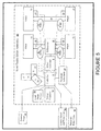
- FIG. 5 shows a schematic diagram of a semi-trailer slider assembly in accordance with another embodiment of the present invention.
- FIG. 7 shows another schematic diagram of a semi-trailer slider assembly in accordance with another embodiment of the present invention.
- FIG. 8 shows another schematic diagram of a semi-trailer with slider assembly in accordance with another embodiment of the present invention.
- FIG. 1 shows an exemplary embodiment of the present invention comprising two motors 2 in electrical connection with an energy storage system 4 , a brake actuator 6 , and an electronic controller 8 .
- the electronic controller 8 monitors the trailer connector 10 for a variety of signals for operator action, including but not limited to braking, turn signals, and back-up signals.
- the trailer connector 10 also can monitor in real-time a variety of trailer operations, including but not limited to the speed of one or more trailer wheels 12 , torque, and one or more accelerometers 14 or similar sensors 15 .
- the energy storage system 4 may comprise one or more energy storage devices, including but not limited to batteries, capacitors 20 , or some combination thereof.
- Capacitors 20 as means of energy storage have several advantages. Capacitors can store energy at fast rates. The regenerative energies from a trailer, including a semi-trailer, need to be transferred from the vehicle's momentum to a stored charge in a matter of seconds. Capacitors can handle these rates without degradation in operational life, whereas batteries cannot. Capacitors have a discharge half-life within a period of days, which is adequate for the starting and stopping to which the typical trailer is subjected.
- Batteries even if properly maintained (e.g., proper temperature, fluid levels, and proper discharging/charging), have a lifetime of only a few years. Capacitors, on the other hand, can last decades before replacement. In addition, supplemental power, such as through a 7-pin signal cable, can supply enough energy to boost the generator to charge depleted storage capacitors or other energy storage devices.
- FIG. 2 shows another exemplary embodiment comprising a single motor 2 .
- the motor is connected to the wheel axle 18 through the differential 16 .
- FIG. 3 shows yet another exemplary embodiment comprising a single motor 2 .
- a motor 2 can be placed on each axle 18 of the trailer, or a motor 2 can be used in conjunction with each wheel 12 .
- a single motor 2 can be used for a trailer regardless of numbers of axles or wheels.
- Motors 2 can be mounted in a variety of ways and locations on the trailer, including hub mounting, axle mounting, differential mounting, or frame mounting.
- the motor or motors 2 power the axles or wheels of the trailer, and recover energy through regenerative braking.
- Power may also be provided or generated from the vehicle pulling the trailer, or by a power generator located on the trailer. Power is transferred to the trailer axles and wheels by typical means, such as differentials and/or gear trains.
- Means of storing and releasing energy can be electrical, hydraulic, pneumatic, or similar means.
- a motor without magnets such as an induction or switched reluctance motor is able to freewheel when in normal trailer operation without generating any unneeded voltages. Accordingly, in one embodiment, use of such motors simplifies the design of the power-switching electronics for the motor and generator.
- a switched reluctance motor can produce large amounts of torque at zero and low speeds, which is desired. This type of motor also is synchronous, thus instantaneous changes in speed and torque can be made.
- Placing one or more motors on a trailer as described above assists various aspects of operation of the trailer. These operations include towing and hitching.
- the invention promotes safety in operation, including assisting in preventing jack-knifing, controlling swerving, and control of the trailer during breakaways.
- the system also can counter shifting in the trailer load during operation (which often happens when transporting live animals or liquids).
- the controller compensates through accelerations and braking of the trailer wheels as appropriate to keep control. This also assists in stability control when encountering speed bumps, potholes, or driving or falling off the edge of the roadway.
- Power can be provided to assist the pulling vehicle when starting or accelerating, and in start-and-go driving conditions.
- the internal combustion engine of the pulling vehicle must produce high power at low speeds at high torque when pulling from a stop or slow rate of speed.
- the pulling vehicle engine under these conditions typically emits high levels of pollutants, has low fuel mileage, and operates at the low end of its efficiency curve.
- the motor or motors 2 can ease this load by providing power to the trailer wheels, easing the load on the pulling vehicle and causing the pulling vehicle engine to be more efficient. Power may also be provided during conditions where the towing load on the pulling vehicle is increased, such as when the trailer is being towed in hilly conditions.
- the electronic controller controls the application of power depending on input from various sensors or accelerometers 14 , 15 , wheel speed, trailer connector inputs, and various other sources of input.
- dual accelerometers may be placed at a 90 degree angle relative to each other, with each at approximately 45 degrees relative to longitudinal axis of the trailer (i.e., at 45 degrees relative to the direction of travel).
- the vector mathematics of the two accelerometers, along with wheel speed and other inputs, enables the electronic controller to determine if the trailer is going up or down a hill, hitting a bump or pothole, turning a corner, accelerating, or braking.
- Accelerometers 70 , 72 , 74 on two or three (or more) axes may be used. In the three axis configuration, this provides three axes of acceleration and angle to effectively monitor the trailer's status.
- the x-axis 70 monitors acceleration and deceleration of the trailer (i.e., along its length), and the angle of inclination of the trailer.
- the y-axis 72 monitors the turning force, or side-to-side motion, and the banking of the road. This information, along with the monitoring of the inner and outer free-wheeling speed sensors on a non-powered axle, can tell the system electronics the degree and rate of turn.
- the z-axis 74 monitors a component of vertical motion, so as to monitor the smoothness of the road, and other inconsistencies such as pot holes or one set of wheels coming off the side of the road onto the shoulder.
- the three axes can be at substantially right angles to each other, but need not be.
- the system can brake the wheels individually, and power others, to keep the trailer stable.
- the system monitors wheel speeds and accelerometer direction and magnitude for indication of acceleration.
- Wheel speed can be measured in a variety of ways, including, but not limited to, wheel speed sensors 24 .
- the controller can calculate the mass of the trailer load. The controller can then apply the proper amounts of torque to assist in acceleration without pushing the vehicle.
- the system of the present invention can obtain an indication of what the driver (and the towed vehicle) is doing.
- the pneumatic valve bank 40 can monitor the incoming pressure from the towing vehicle and the outgoing pressure to the individual pneumatic brakes 44 .
- the system can determine how the brake for that wheel is performing. Monitoring of pressure can be accomplished by one or more pressure sensors 42 .
- the system can brake the wheels individually and power others to keep the trailer stable. This combination of braking and powering at the same time will help the trailer track the towing vehicle.
- Power can be regained through regenerative braking.
- the present system can watch the brake signal from the trailer connector, the deceleration of wheel speeds, and/or the accelerometer direction and magnitude data for indication of braking conditions.
- Regenerated energy would be stored in the energy storage system 4 , which may include one or more batteries or capacitors 20 as described above, until the energy storage system is fully charged.
- Regenerative braking thus may occur until the energy storage system is fully charged, or until the wheel speed has dropped to a minimum level.
- Normal braking such as hydraulic braking, can then take over.
- the electronic controller can apply the proper amount of braking to each wheel, or to the wheels on each side of the trailer, to keep the trailer from “pushing” the towing vehicle and thereby reduce the potential of jack-knifing or other dangerous conditions during operation.
- an electro-hydraulic brake actuator 6 may be used as the regenerative braking interface.
- Said actuator may comprise a large capacity reservoir, hydraulic pump, solid state electronics, and adjustable pressure output to the brakes via an interface, such as a serial interface.
- the hydraulic brakes provide the proportion of braking that needs to be made up for the appropriate deceleration. As the trailer slows down, the regenerative braking becomes less prominent, and the hydraulic braking finishes the stop.
- the regenerative braking can be continued after the capacitors or energy storage devices have reached maximum charging capacity. Excess energy could be directed or dumped into load resistors 50 , as shown in FIGS. 5-7 .
- This dumping of load can be proportionately applied to both capacitors and resistors as the system reaches maximum charging capacity while still providing maximum braking capacity. By doing this, the trailer maintains even braking and lightens the load on the mechanical braking system.
- Regenerative braking into the capacitor and/or resistive load along with the pneumatic brakes that are controlled through a pneumatic valve bank eliminates the need for the tractor to implement the need for loud “jake-braking.” By applying both regenerative braking and friction braking, the vehicle can brake much faster with shorter stopping distances. This system also reduces wear on the brake system and drive train.
- the generator portion of the system can be used to supply power to the trailer, such as for refrigeration, heaters, and/or lights.
- This external power 58 may also be used to energize the cargo, or portions thereof, that the trailer may be carrying.
- the present invention can enhance safety by controlling the trailer during a break-away situation.
- the electronic controller can apply the brake actuator to apply the brakes and also power the motors (if necessary) to keep the trailer upright and true, and keep the wheels in maximum braking traction to the road.
- the accelerometer and wheel speed sensor data also can enable the controller to determine the course and direction of the trailer, allowing the controller to apply the proper amount of braking to the respective wheels to keep the trailer on a straight and upright course (thereby preventing the trailer from tipping and rolling over) until it comes to a stop.
- the system of the present invention may be embedded within the slider unit 90 of a semi-trailer 94 (see FIGS. 5 to 8 ).
- Existing trailers have only pneumatic brake lines 38 attached to the slider from the main body of the trailer.
- Existing sliders can be moved either forward or backward to help balance the load on the trailer's axles. Because the present invention can be completely contained with the slider unit, existing trailers can be easily retrofitted with the new mechanism. Down times for conversion would be minimal. New trailers being built also would have quicker assembly times with this configuration.
- the invention would only have the existing pneumatic brake lines reattached (including, but not limited to, with a quick coupler), and a cable to monitor the existing signaling cable 36 (which typically is 7-pin for current semi-trailers) that contains the lines for power, brakes, signals, and marker lamps.
- the motoring/regenerating on/off can come either manually (such as using a switch on the slider or elsewhere) or remotely (e.g., by monitoring the brake line). In one embodiment using the latter method, if the driver taps in rapid succession a certain number of times (three, for example) on the brakes, the unit would toggle on and off.
- An indicator light or lamp 92 on a side or each side of the slider unit could be used to indicate its on/off state, and could be positioned to be visible in the rear view mirror of the tractor or pulling vehicle.
- the trailer controls may be independent of the towing vehicle or tractor, or may be connected to the towing vehicle.
- the connection to the trailer controls, wherever located, may be wireless or by wires or lines.
- on-scale or load sensors 98 may be used to gauge the mass of the trailer load.
- the sensors may be in either load cells, the air suspension systems, or another suitable location. This will help the system calculate how much torque to apply through the motors to help assist the trailer in forward motion (but not too much so as to push the trailer). Similarly, this method can be used to help the brakes provide the right amount of deceleration.
Landscapes
- Engineering & Computer Science (AREA)
- Power Engineering (AREA)
- Transportation (AREA)
- Mechanical Engineering (AREA)
- Regulating Braking Force (AREA)
- Electric Propulsion And Braking For Vehicles (AREA)
Abstract
A system and related method for a regenerative braking system on a towed vehicle, such as a trailer or semi-trailer. The system provides power and braking to the respective trailer wheels, as needed, to help stabilize the trailer. Power is regenerated during braking. While batteries may be used to store the energy, the system also may use capacitive storage units, which charge and discharge large amounts of energy at a fast rate. A multiple-axis sensor system in conjunction with wheel sensors, load sensors, and proportional control of the brakes and motor power to the axles and wheels, is used to achieve superior load stabilization. The invention can be easily retrofit into new or used trailers, and is self-contained with low maintenance.
Description
This application claims benefit of, and priority to, U.S. Provisional Patent Application No. 60/883,215, filed Jan. 3, 2007, U.S. Provisional Application No. 60/883,219, filed Jan. 3, 2007, and U.S. Provisional Patent Application No. 60/950,014, filed Jul. 16, 2007, each entitled “HYBRID TRAILER SYSTEM.” The complete specifications, drawings, attachments and disclosures of U.S. Provisional Patent Application Nos. 60/883,215, 60/883,219 and 60/950,014 are incorporated herein by specific reference.
This invention relates to a hybrid trailer system and apparatus. More particularly, the invention relates to a system and apparatus for placing one or more motors on a trailer to assist in operation of the trailer.
At present, there are no trailer axle assemblies known being produced that can collect kinetic energy during deceleration of the vehicle, and retrieve that energy for acceleration. In particular, there is no such assembly in a package that can be easily retrofit into new or used trailers, including semi-trailers, that is completely self-contained, and can be connected to an ordinary, unmodified semi-tractor. Conventional semi-tractors do not have the room to add a new or retrofit hybrid system.
Current tractor trailers received their power from an ICE located in the tractor. The trailer provides only the means to handle the load. When an ICE tractor accelerates from rest, the engine emits large amounts of pollutants. ICE does not have high torque from zero to low RPMs. When the tractor decelerates, the brakes from the tractor and trailer must dissipate large amounts of kinetic energy through heat or by “jake braking,” the process by which the energy is pushed back through the ICE causing large amounts of noise.
Current tractor-trailer systems also have a lower response time to traffic flow changes due to the heavy load being hauled. A tractor's ICE can only provide so much power for quick acceleration.
Some semi-trailers are equipped with ABS (anti-lock breaking system) as a part of their braking systems to help stabilize the trailer. ABS only helps the trailer wheels get better traction during deceleration, however.
The use of batteries to power an electric motor on a semi-trailer is known, but a problem with the use of batteries is the high amount of power that these devices must absorb in a short period of time during braking. Batteries can hold large amounts of power, in general, but they charge and discharge at slow rates. Increasing the charge and discharge rates results in a shortened lifespan of the battery. In addition, all batteries have a limited life span, and need to be replaced periodically. Batteries also contain corrosive elements that can spill if damaged.
Accordingly, what is needed is a system to collect kinetic energy during deceleration of the vehicle, and retrieve that energy for acceleration, while being easily retrofit into new or used trailers, including semi-trailers. The system should be self-contained that is completely self-contained, and can be connected to an ordinary, unmodified semi-tractor. The system also needs to charge and discharge large amounts of energy at a fast rate, and should have a multiple-axis detection system.
In one exemplary embodiment, the present invention comprises a system and method for towing a trailer, including but not limited to a semi-trailer, which overcomes the above drawbacks of prior art systems and methods. The invention can be easily retrofit into new or used trailers, and is self-contained with low maintenance. By placing the system in or on the trailer, the system becomes a hybrid system.
The system provides power and braking to the respective trailer wheels, as needed, to help stabilize the trailer. While batteries may be used to store energy, the system also may use capacitive storage units, which charge and discharge large amounts of energy at a fast rate. Said units also are safer than batteries when damaged.
In an exemplary embodiment, the present system has a multiple-axis sensor system. A three-axis accelerometer system can detect the vehicle's acceleration and deceleration (x-axis), inclination and turning force (y-axis), and how rough the road is, and whether the trailer has gone off the side of the road (z-axis). With wheel sensors, load sensors, and proportional control of the brakes and motor power to the axles and wheels, superior load stabilization can be achieved.
The present system allows for quieter and even silent regenerative braking of the trailer after the energy storage systems have reached capacity by using resistive load banks, thereby eliminating the need for “Jake breaking.”
The present invention is a system and apparatus for a hybrid trailer. FIG. 1 shows an exemplary embodiment of the present invention comprising two motors 2 in electrical connection with an energy storage system 4, a brake actuator 6, and an electronic controller 8. The electronic controller 8 monitors the trailer connector 10 for a variety of signals for operator action, including but not limited to braking, turn signals, and back-up signals. The trailer connector 10 also can monitor in real-time a variety of trailer operations, including but not limited to the speed of one or more trailer wheels 12, torque, and one or more accelerometers 14 or similar sensors 15. The energy storage system 4 may comprise one or more energy storage devices, including but not limited to batteries, capacitors 20, or some combination thereof.
Batteries, even if properly maintained (e.g., proper temperature, fluid levels, and proper discharging/charging), have a lifetime of only a few years. Capacitors, on the other hand, can last decades before replacement. In addition, supplemental power, such as through a 7-pin signal cable, can supply enough energy to boost the generator to charge depleted storage capacitors or other energy storage devices.
In other configurations, a motor 2 can be placed on each axle 18 of the trailer, or a motor 2 can be used in conjunction with each wheel 12. Alternatively, a single motor 2 can be used for a trailer regardless of numbers of axles or wheels.
A motor without magnets such as an induction or switched reluctance motor is able to freewheel when in normal trailer operation without generating any unneeded voltages. Accordingly, in one embodiment, use of such motors simplifies the design of the power-switching electronics for the motor and generator. A switched reluctance motor can produce large amounts of torque at zero and low speeds, which is desired. This type of motor also is synchronous, thus instantaneous changes in speed and torque can be made.
Placing one or more motors on a trailer as described above assists various aspects of operation of the trailer. These operations include towing and hitching. In addition, the invention promotes safety in operation, including assisting in preventing jack-knifing, controlling swerving, and control of the trailer during breakaways. The system also can counter shifting in the trailer load during operation (which often happens when transporting live animals or liquids). The controller compensates through accelerations and braking of the trailer wheels as appropriate to keep control. This also assists in stability control when encountering speed bumps, potholes, or driving or falling off the edge of the roadway.
Power can be provided to assist the pulling vehicle when starting or accelerating, and in start-and-go driving conditions. The internal combustion engine of the pulling vehicle must produce high power at low speeds at high torque when pulling from a stop or slow rate of speed. The pulling vehicle engine under these conditions typically emits high levels of pollutants, has low fuel mileage, and operates at the low end of its efficiency curve. The motor or motors 2 can ease this load by providing power to the trailer wheels, easing the load on the pulling vehicle and causing the pulling vehicle engine to be more efficient. Power may also be provided during conditions where the towing load on the pulling vehicle is increased, such as when the trailer is being towed in hilly conditions.
With the boost in power during acceleration and when going up an incline, the towing vehicle can reach a particular speed more quickly and without expelling large amounts of pollutants. The regenerative braking during decelerations and when going down a decline recharges the system. Together, this balances the energy loading of the system.
The electronic controller controls the application of power depending on input from various sensors or accelerometers 14, 15, wheel speed, trailer connector inputs, and various other sources of input. In one exemplary configuration, dual accelerometers may be placed at a 90 degree angle relative to each other, with each at approximately 45 degrees relative to longitudinal axis of the trailer (i.e., at 45 degrees relative to the direction of travel). The vector mathematics of the two accelerometers, along with wheel speed and other inputs, enables the electronic controller to determine if the trailer is going up or down a hill, hitting a bump or pothole, turning a corner, accelerating, or braking.
In one embodiment, the system monitors wheel speeds and accelerometer direction and magnitude for indication of acceleration. Wheel speed can be measured in a variety of ways, including, but not limited to, wheel speed sensors 24. By applying an incremental torque and watching the wheel speed the controller can calculate the mass of the trailer load. The controller can then apply the proper amounts of torque to assist in acceleration without pushing the vehicle.
By monitoring signal lines 36 and the pneumatic brake lines 38, the system of the present invention can obtain an indication of what the driver (and the towed vehicle) is doing. The pneumatic valve bank 40 can monitor the incoming pressure from the towing vehicle and the outgoing pressure to the individual pneumatic brakes 44. By monitoring the feedback pressure of each wheel's brake lines, and their respective wheel speeds, the system can determine how the brake for that wheel is performing. Monitoring of pressure can be accomplished by one or more pressure sensors 42. The system can brake the wheels individually and power others to keep the trailer stable. This combination of braking and powering at the same time will help the trailer track the towing vehicle. This is of importance in all driving situations, including, but not limited to, straight-aways, curves (e.g., by applying more power to the outer wheels than the inner wheels), and circumstances where there is a difference in road mediums (e.g., one set of tires off in the shoulder and the other on the blacktop road; dirt roads; wet roads; and icy roads). Because the system of the present invention can determine if the road conditions are slippery (such as due to ice, snow, water, or other substances on the road), it can take proper precautions in the method of braking and motoring, or, if the situation arises, turn itself off.
Power can be regained through regenerative braking. The present system can watch the brake signal from the trailer connector, the deceleration of wheel speeds, and/or the accelerometer direction and magnitude data for indication of braking conditions. Regenerated energy would be stored in the energy storage system 4, which may include one or more batteries or capacitors 20 as described above, until the energy storage system is fully charged. Regenerative braking thus may occur until the energy storage system is fully charged, or until the wheel speed has dropped to a minimum level. Normal braking, such as hydraulic braking, can then take over. The electronic controller can apply the proper amount of braking to each wheel, or to the wheels on each side of the trailer, to keep the trailer from “pushing” the towing vehicle and thereby reduce the potential of jack-knifing or other dangerous conditions during operation.
In one exemplary embodiment, an electro-hydraulic brake actuator 6 may be used as the regenerative braking interface. Said actuator may comprise a large capacity reservoir, hydraulic pump, solid state electronics, and adjustable pressure output to the brakes via an interface, such as a serial interface. When regenerative braking is in effect, the hydraulic brakes provide the proportion of braking that needs to be made up for the appropriate deceleration. As the trailer slows down, the regenerative braking becomes less prominent, and the hydraulic braking finishes the stop.
In another embodiment, the regenerative braking can be continued after the capacitors or energy storage devices have reached maximum charging capacity. Excess energy could be directed or dumped into load resistors 50, as shown in FIGS. 5-7 . This dumping of load can be proportionately applied to both capacitors and resistors as the system reaches maximum charging capacity while still providing maximum braking capacity. By doing this, the trailer maintains even braking and lightens the load on the mechanical braking system. Regenerative braking into the capacitor and/or resistive load along with the pneumatic brakes that are controlled through a pneumatic valve bank eliminates the need for the tractor to implement the need for loud “jake-braking.” By applying both regenerative braking and friction braking, the vehicle can brake much faster with shorter stopping distances. This system also reduces wear on the brake system and drive train.
In another exemplary embodiment, the generator portion of the system can be used to supply power to the trailer, such as for refrigeration, heaters, and/or lights. This external power 58 may also be used to energize the cargo, or portions thereof, that the trailer may be carrying.
In another configuration, the present invention can enhance safety by controlling the trailer during a break-away situation. When a break-away situation is detected (such as by a break-away switch 80 tethered from the trailer to the towing vehicle, or by a loss of signal from the pneumatic and/or electrical lines), the electronic controller can apply the brake actuator to apply the brakes and also power the motors (if necessary) to keep the trailer upright and true, and keep the wheels in maximum braking traction to the road. The accelerometer and wheel speed sensor data also can enable the controller to determine the course and direction of the trailer, allowing the controller to apply the proper amount of braking to the respective wheels to keep the trailer on a straight and upright course (thereby preventing the trailer from tipping and rolling over) until it comes to a stop.
In yet another embodiment, the system of the present invention may be embedded within the slider unit 90 of a semi-trailer 94 (see FIGS. 5 to 8 ). Existing trailers have only pneumatic brake lines 38 attached to the slider from the main body of the trailer. Existing sliders can be moved either forward or backward to help balance the load on the trailer's axles. Because the present invention can be completely contained with the slider unit, existing trailers can be easily retrofitted with the new mechanism. Down times for conversion would be minimal. New trailers being built also would have quicker assembly times with this configuration. The invention would only have the existing pneumatic brake lines reattached (including, but not limited to, with a quick coupler), and a cable to monitor the existing signaling cable 36 (which typically is 7-pin for current semi-trailers) that contains the lines for power, brakes, signals, and marker lamps. The motoring/regenerating on/off can come either manually (such as using a switch on the slider or elsewhere) or remotely (e.g., by monitoring the brake line). In one embodiment using the latter method, if the driver taps in rapid succession a certain number of times (three, for example) on the brakes, the unit would toggle on and off. An indicator light or lamp 92 on a side or each side of the slider unit could be used to indicate its on/off state, and could be positioned to be visible in the rear view mirror of the tractor or pulling vehicle.
The trailer controls may be independent of the towing vehicle or tractor, or may be connected to the towing vehicle. The connection to the trailer controls, wherever located, may be wireless or by wires or lines.
The system also may be used for autonomous trailer hitching or movement with a jack 30 on a set of coaster wheels 32 or tracks (which may be useful in muddy conditions) at the hitch beam, as shown in FIG. 4 . The jack may be powered. The motor or motors 2 can then be used to drive the trailer in forward or reverse. Where two or more motors are used, the motors can also be used to assist in turning the vehicle, by running the motor on one side and not the other, or running the motor on one side in reverse. The operator can use a controller 34, such as a pennant hand-held controller or wireless device, to control trailer movement. This means of operation can be useful in moving a trailer to a vehicle for hitching, or moving a trailer independently of a towing vehicle, such as moving or backing a trailer into a tight storage or parking spot.
In another embodiment, on-scale or load sensors 98 may be used to gauge the mass of the trailer load. The sensors may be in either load cells, the air suspension systems, or another suitable location. This will help the system calculate how much torque to apply through the motors to help assist the trailer in forward motion (but not too much so as to push the trailer). Similarly, this method can be used to help the brakes provide the right amount of deceleration.
In yet another embodiment, all of the data collected and/or generated by the system can be stored. This storage can be in the controller 8. This data can be retrieved by a laptop, memory stick or device, or by wireless transmission, and used to monitor the driver, the truck, and the load.
Thus, it should be understood that the embodiments and examples described herein have been chosen and described in order to best illustrate the principles of the invention and its practical applications to thereby enable one of ordinary skill in the art to best utilize the invention in various embodiments and with various modifications as are suited for particular uses contemplated. Even though specific embodiments of this invention have been described, they are not to be taken as exhaustive. There are several variations that will be apparent to those skilled in the art.
Claims (20)
1. A regenerative braking system for a towed vehicle, comprising:
one or more motors mounted on a separate slider unit adapted to be removably attached to a towed vehicle, said motor or motors adapted to recover energy from regenerative braking of the towed vehicle when the slider unit is attached to the towed vehicle;
an energy storage system mounted on said slider unit in electrical connection with said motor or motors; and
an electronic controller mounted on said slider unit and adapted to monitor a trailer connection between the towed vehicle and a towing vehicle when the slider unit is attached to the towed vehicle.
2. The system of claim 1 , further comprising:
at least one multiple-axis sensor mounted on the slider unit.
3. The system of claim 1 , wherein the energy storage system comprises one or more capacitors or batteries.
4. The system of claim 1 , wherein the motor or motors are adapted to apply power to one or more wheels of the towed vehicle when the slider unit is attached to the towed vehicle.
5. The system of claim 1 , wherein the electronic controller controls the application of power from the motor or motors based on data from the trailer connection.
6. The system of claim 1 , wherein the towed vehicle is a semi-trailer.
7. The system of claim 1 , further comprising one or more load resistors connected to the energy storage system.
8. The system of claim 1 , further comprising a brake actuator.
9. The system of claim 1 , wherein energy generated from the system is used to supply power to cargo being transported on the towed vehicle.
10. The system of claim 1 , wherein the system can be turned off from a towing vehicle.
11. The system of claim 1 , wherein wheels of the towed vehicle can be independently powered or braked by the system.
12. The system of claim 1 , wherein there is a motor for each wheel or axle of the towed vehicle.
13. The system of claim 1 , further comprising:
a load sensor connected to the electronic controller, the load sensor adapted to determine the mass of the load in the towed vehicle, wherein the controller determines the amount of torque the motor or motors need to generate to assist in the acceleration or deceleration of the towed vehicle based on input from the load sensor.
14. The system of claim 1 , wherein the motor or motors are switched-reluctance motors.
15. The system of claim 2 , wherein the motor or motors are adapted to apply power to one or more wheels of the towed vehicle when the slider unit is attached to the towed vehicle.
16. The system of claim 2 , wherein the electronic controller controls the application of power from the motor or motors based on data from the multiple-axis sensor.
17. The system of claim 2 , wherein the electronic controller controls the application of power from the motor or motors based on data from one or more of the following: the multiple-axis sensor, the trailer connection, and the wheel speed of the towed vehicle.
18. The system of claim 2 , wherein the multiple-axis sensor comprises three axes: an x-axis adapted to monitor the acceleration and deceleration and angle of inclination of the trailer; a y-axis adapted to monitor the turning force and banking of the driving surface; and a z-axis to monitor the smoothness of the driving surface.
19. The system of claim 7 , wherein regenerative braking continues after the energy storage system has reached maximum charging capacity by directing excess energy to the load resistors.
20. The system of claim 10 , wherein the system can be turned off by three or more taps of a brake on the towing vehicle.
Priority Applications (1)
| Application Number | Priority Date | Filing Date | Title |
|---|---|---|---|
| US11/968,845 US8215436B2 (en) | 2007-01-03 | 2008-01-03 | Hybrid trailer system |
Applications Claiming Priority (4)
| Application Number | Priority Date | Filing Date | Title |
|---|---|---|---|
| US88321907P | 2007-01-03 | 2007-01-03 | |
| US88321507P | 2007-01-03 | 2007-01-03 | |
| US95001407P | 2007-07-16 | 2007-07-16 | |
| US11/968,845 US8215436B2 (en) | 2007-01-03 | 2008-01-03 | Hybrid trailer system |
Publications (2)
| Publication Number | Publication Date |
|---|---|
| US20080169144A1 US20080169144A1 (en) | 2008-07-17 |
| US8215436B2 true US8215436B2 (en) | 2012-07-10 |
Family
ID=39609307
Family Applications (1)
| Application Number | Title | Priority Date | Filing Date |
|---|---|---|---|
| US11/968,845 Expired - Fee Related US8215436B2 (en) | 2007-01-03 | 2008-01-03 | Hybrid trailer system |
Country Status (2)
| Country | Link |
|---|---|
| US (1) | US8215436B2 (en) |
| WO (1) | WO2008086087A2 (en) |
Cited By (62)
| Publication number | Priority date | Publication date | Assignee | Title |
|---|---|---|---|---|
| US20090271068A1 (en) * | 2008-04-29 | 2009-10-29 | Nuctech Company Limited | Detection Apparatus |
| US20100065344A1 (en) * | 2008-09-12 | 2010-03-18 | Collings Iii John K | Self Propelled Electric Vehicle Recharging Trailer |
| US20110005848A1 (en) * | 2008-02-29 | 2011-01-13 | Volvo Construction Equipment Ab | Work machine |
| US20110042154A1 (en) * | 2009-08-19 | 2011-02-24 | Brian Daniel Bartel | System and method for towing a trailer |
| US20120006108A1 (en) * | 2010-07-12 | 2012-01-12 | Avl List Gmbh | Method and test platform for developing a motor vehicle with several powered axles |
| US20120259493A1 (en) * | 2011-04-05 | 2012-10-11 | American SportWorks LLC | Utility vehicle |
| US20130079980A1 (en) * | 2011-09-23 | 2013-03-28 | Carl T. Vuk | Towed vehicle arrangement responsive to vehicle acceleration and deceleration |
| US20140025245A1 (en) * | 2010-12-16 | 2014-01-23 | Gkn Autostructure Limited | Tractor/Trailer Combinations |
| US20140110186A1 (en) * | 2012-10-22 | 2014-04-24 | Truma Geraetetechnik Gmbh & Co. Kg | Maneuvering drive with additional brake module |
| US9290202B2 (en) | 2011-04-19 | 2016-03-22 | Ford Global Technologies, Llc | System and method of calibrating a trailer backup assist system |
| US9290203B2 (en) | 2011-04-19 | 2016-03-22 | Ford Global Technologies, Llc | Trailer length estimation in hitch angle applications |
| US9315212B1 (en) | 2014-10-13 | 2016-04-19 | Ford Global Technologies, Llc | Trailer sensor module and associated method of wireless trailer identification and motion estimation |
| US9335163B2 (en) | 2011-04-19 | 2016-05-10 | Ford Global Technologies, Llc | Trailer length estimation in hitch angle applications |
| US9340228B2 (en) | 2014-10-13 | 2016-05-17 | Ford Global Technologies, Llc | Trailer motion and parameter estimation system |
| US9373044B2 (en) | 2011-07-25 | 2016-06-21 | Ford Global Technologies, Llc | Trailer lane departure warning system |
| US9425671B1 (en) | 2014-07-01 | 2016-08-23 | Arie Allen Van Meveren | Low-speed towed power generating apparatus |
| US9434414B2 (en) | 2011-04-19 | 2016-09-06 | Ford Global Technologies, Llc | System and method for determining a hitch angle offset |
| DE102015208113A1 (en) * | 2015-04-30 | 2016-11-03 | Deere & Company | Retarder brake system of a vehicle combination |
| US9513103B2 (en) | 2011-04-19 | 2016-12-06 | Ford Global Technologies, Llc | Hitch angle sensor assembly |
| US9517668B2 (en) | 2014-07-28 | 2016-12-13 | Ford Global Technologies, Llc | Hitch angle warning system and method |
| US9522699B2 (en) | 2015-02-05 | 2016-12-20 | Ford Global Technologies, Llc | Trailer backup assist system with adaptive steering angle limits |
| US9533683B2 (en) | 2014-12-05 | 2017-01-03 | Ford Global Technologies, Llc | Sensor failure mitigation system and mode management |
| US9566911B2 (en) | 2007-03-21 | 2017-02-14 | Ford Global Technologies, Llc | Vehicle trailer angle detection system and method |
| US9607242B2 (en) | 2015-01-16 | 2017-03-28 | Ford Global Technologies, Llc | Target monitoring system with lens cleaning device |
| US9610975B1 (en) | 2015-12-17 | 2017-04-04 | Ford Global Technologies, Llc | Hitch angle detection for trailer backup assist system |
| US9616923B2 (en) * | 2015-03-03 | 2017-04-11 | Ford Global Technologies, Llc | Topographical integration for trailer backup assist system |
| US9683848B2 (en) | 2011-04-19 | 2017-06-20 | Ford Global Technologies, Llc | System for determining hitch angle |
| FR3046592A1 (en) * | 2016-01-07 | 2017-07-14 | Mack Murray | HYBRIDIZATION DEVICE |
| US9798953B2 (en) | 2015-12-17 | 2017-10-24 | Ford Global Technologies, Llc | Template matching solution for locating trailer hitch point |
| US9796228B2 (en) | 2015-12-17 | 2017-10-24 | Ford Global Technologies, Llc | Hitch angle detection for trailer backup assist system |
| US9804022B2 (en) | 2015-03-24 | 2017-10-31 | Ford Global Technologies, Llc | System and method for hitch angle detection |
| US9827818B2 (en) | 2015-12-17 | 2017-11-28 | Ford Global Technologies, Llc | Multi-stage solution for trailer hitch angle initialization |
| US9836060B2 (en) | 2015-10-28 | 2017-12-05 | Ford Global Technologies, Llc | Trailer backup assist system with target management |
| US9937953B2 (en) | 2011-04-19 | 2018-04-10 | Ford Global Technologies, Llc | Trailer backup offset determination |
| US9963004B2 (en) | 2014-07-28 | 2018-05-08 | Ford Global Technologies, Llc | Trailer sway warning system and method |
| US10005492B2 (en) | 2016-02-18 | 2018-06-26 | Ford Global Technologies, Llc | Trailer length and hitch angle bias estimation |
| US10011228B2 (en) | 2015-12-17 | 2018-07-03 | Ford Global Technologies, Llc | Hitch angle detection for trailer backup assist system using multiple imaging devices |
| US10017115B2 (en) | 2015-11-11 | 2018-07-10 | Ford Global Technologies, Llc | Trailer monitoring system and method |
| EP3356175A1 (en) * | 2015-09-28 | 2018-08-08 | Carrier Corporation | A vehicle comprising a wheel driven generator for charging a battery |
| US10046800B2 (en) | 2016-08-10 | 2018-08-14 | Ford Global Technologies, Llc | Trailer wheel targetless trailer angle detection |
| US10106193B2 (en) | 2016-07-01 | 2018-10-23 | Ford Global Technologies, Llc | Enhanced yaw rate trailer angle detection initialization |
| US10150358B2 (en) * | 2015-12-17 | 2018-12-11 | Erik Orlando Soto | Generator and electrical motor for multi-axle vehicles |
| US10155478B2 (en) | 2015-12-17 | 2018-12-18 | Ford Global Technologies, Llc | Centerline method for trailer hitch angle detection |
| US10160428B2 (en) | 2016-02-05 | 2018-12-25 | Dewel, LLC | Trailer break-away switch |
| US10196088B2 (en) | 2011-04-19 | 2019-02-05 | Ford Global Technologies, Llc | Target monitoring system and method |
| US10222804B2 (en) | 2016-10-21 | 2019-03-05 | Ford Global Technologies, Llc | Inertial reference for TBA speed limiting |
| US10384607B2 (en) | 2015-10-19 | 2019-08-20 | Ford Global Technologies, Llc | Trailer backup assist system with hitch angle offset estimation |
| US10611407B2 (en) | 2015-10-19 | 2020-04-07 | Ford Global Technologies, Llc | Speed control for motor vehicles |
| WO2020107086A1 (en) | 2018-11-27 | 2020-06-04 | Fras-Le S.A. | System for smart coupling between a road implement and a tractor vehicle, system and method for managing the actuation of auxiliary traction on road implements |
| US10710585B2 (en) | 2017-09-01 | 2020-07-14 | Ford Global Technologies, Llc | Trailer backup assist system with predictive hitch angle functionality |
| US10752102B2 (en) | 2018-03-22 | 2020-08-25 | John B. Lampsa | Trailer mounted battery range extender for electric truck tractor |
| US10829046B2 (en) | 2019-03-06 | 2020-11-10 | Ford Global Technologies, Llc | Trailer angle detection using end-to-end learning |
| US11077795B2 (en) | 2018-11-26 | 2021-08-03 | Ford Global Technologies, Llc | Trailer angle detection using end-to-end learning |
| US20220126714A1 (en) * | 2020-10-22 | 2022-04-28 | GM Global Technology Operations LLC | Battery-electric-vehicle assisted towing concept |
| US11760168B2 (en) | 2018-10-03 | 2023-09-19 | Carrier Corporation | Anti-lock tire system |
| US11794706B2 (en) | 2021-07-01 | 2023-10-24 | Daniel H. Crouse | Safety and control system for use when pulling trailers |
| US11958383B2 (en) | 2021-03-14 | 2024-04-16 | Toyota Motor Engineering & Manufacturing North America, Inc. | Regenerative braking control system |
| US12011975B2 (en) | 2018-10-03 | 2024-06-18 | Carrier Corporation | Generator movement control |
| US12172641B2 (en) | 2019-05-15 | 2024-12-24 | Ford Global Technologies, Llc | Electrified vehicle configured to selectively increase energy recovery threshold and corresponding method |
| US12275331B2 (en) | 2021-03-14 | 2025-04-15 | Toyota Motor Engineering & Manufacturing North America, Inc. | Regenerative braking control system |
| US12539765B2 (en) | 2021-03-14 | 2026-02-03 | Toyota Motor Engineering & Manufacturing North America, Inc. | Regenerative braking control system that adjusts regenerative braking settings based on driving environment condition |
| US12545066B2 (en) | 2021-11-09 | 2026-02-10 | Outrider Technologies, Inc. | Autonomous trailer connectivity |
Families Citing this family (71)
| Publication number | Priority date | Publication date | Assignee | Title |
|---|---|---|---|---|
| US7743859B2 (en) * | 2006-02-03 | 2010-06-29 | Magna Powertrain Usa, Inc. | Hybrid drivetrains for trailers |
| WO2009059401A1 (en) * | 2007-11-09 | 2009-05-14 | University Of Manitoba | Auxiliary drive device |
| US20100051364A1 (en) * | 2008-08-28 | 2010-03-04 | Yadon Arad | Apparatus for assisting motion of vehicles |
| GB2467101B (en) * | 2008-11-28 | 2013-05-01 | Knorr Bremse Systeme | Road laying apparatus |
| GB2466086B (en) * | 2009-06-16 | 2011-01-26 | Protean Electric Ltd | A trailer |
| WO2011108948A1 (en) * | 2010-03-05 | 2011-09-09 | Robert Malcolm Sharp | Propulsion device and method |
| US8571777B2 (en) * | 2010-08-13 | 2013-10-29 | Robert Bosch Gmbh | Independent trailer sway controller |
| US20130079979A1 (en) * | 2011-09-23 | 2013-03-28 | Alan D. Sheidler | Towed vehicle arrangement responsive to lateral hitch loading |
| US9037346B2 (en) * | 2011-09-23 | 2015-05-19 | Deere & Company | Steering control for vehicle trains |
| US20130076497A1 (en) * | 2011-09-23 | 2013-03-28 | Alan D. Sheidler | Vehicle arrangement responsive to amount of material in a towed vehicle |
| EP2794313A1 (en) * | 2011-12-19 | 2014-10-29 | Carrier Corporation | Transport refrigeration system with regenerative elements |
| CA2926291C (en) | 2012-10-19 | 2022-04-05 | Chris FORSBERG | Systems and methods for mounting a fuel system |
| US9026311B1 (en) * | 2013-03-13 | 2015-05-05 | Tuson Rv Brakes, Llc | Trailer sway detection and method for reducing trailer sway utilizing trailer brakes |
| GB201310712D0 (en) * | 2013-06-16 | 2013-07-31 | Mangion Charles J | Early jackknife correctional system |
| FR3023533A1 (en) * | 2014-07-10 | 2016-01-15 | Mack Higdon Murray | DEVICE FOR HYBRIDIZING A SEMI-TRAILER |
| US10112536B2 (en) * | 2014-08-08 | 2018-10-30 | Bendix Commercial Vehicle Systems Llc | System and method for associating camera sensors on a vehicle |
| US11618376B2 (en) | 2014-10-30 | 2023-04-04 | Crc R&D, Llc | Methods, apparatuses, and systems for monitoring state of a transportation system |
| US9914392B2 (en) * | 2014-10-30 | 2018-03-13 | Cross Road Centers, Llc | Methods, apparatuses, and systems for monitoring state of a transportation system |
| US9340197B1 (en) * | 2015-01-23 | 2016-05-17 | Robert Bosch Gmbh | Vehicle and method of controlling |
| US20160243908A1 (en) * | 2015-02-20 | 2016-08-25 | GM Global Technology Operations LLC | Semi-autonomous trailer hitch |
| US10245972B2 (en) | 2015-05-01 | 2019-04-02 | Hyliion Inc. | Trailer-based energy capture and management |
| US12024029B2 (en) | 2015-05-01 | 2024-07-02 | Hyliion Inc. | Trailer-based energy capture and management |
| US10596913B2 (en) | 2015-05-01 | 2020-03-24 | Hyliion Inc. | Trailer-based energy capture and management |
| US9694712B2 (en) | 2015-05-01 | 2017-07-04 | Hyliion Inc. | Motor vehicle accessory to increase power supply and reduce fuel requirements |
| KR101679972B1 (en) * | 2015-05-18 | 2016-11-25 | 현대자동차주식회사 | Apparatus for controlling brake of tractor and method thereof |
| GB2545642B (en) * | 2015-12-15 | 2020-01-29 | Jaguar Land Rover Ltd | Traction battery charging method and apparatus |
| DE102016003356A1 (en) * | 2016-03-18 | 2017-09-21 | Wabco Gmbh | Electronic brake system |
| DE102016212071B4 (en) * | 2016-07-04 | 2019-02-14 | Audi Ag | Method for operating an electrically driven or electrically driven vehicle and vehicle |
| DE102016010574A1 (en) * | 2016-09-02 | 2018-03-08 | Man Truck & Bus Ag | Road vehicle train combination, especially as a long commercial vehicle combination |
| DE102016010575A1 (en) * | 2016-09-02 | 2018-03-08 | Man Truck & Bus Ag | Road vehicle train combination with a tractor and a trailer as semi-trailer |
| IT201600090263A1 (en) * | 2016-09-06 | 2018-03-06 | Drop S R L | VEHICLE TRAILER CONTROL DEVICE |
| US10821853B2 (en) | 2016-09-30 | 2020-11-03 | Hyliion Inc. | Vehicle energy management system and related methods |
| US10500975B1 (en) | 2016-09-30 | 2019-12-10 | Hyliion Inc. | Vehicle weight estimation system and related methods |
| US10906545B2 (en) * | 2016-12-22 | 2021-02-02 | Blackberry Limited | Adjusting mechanical elements of cargo transportation units |
| US10766478B2 (en) * | 2017-02-17 | 2020-09-08 | Hyliion Inc. | Tractor unit with on-board regenerative braking energy storage for stopover HVAC operation without engine idle |
| US10202106B1 (en) * | 2017-08-08 | 2019-02-12 | Ford Global Technologies, Llc | Vehicle trailer detection |
| GB2566492B (en) * | 2017-09-15 | 2020-06-17 | Jaguar Land Rover Ltd | System and method for a trailer towable by a vehicle |
| GB2566494A (en) * | 2017-09-15 | 2019-03-20 | Jaguar Land Rover Ltd | System and method for a trailer towable by a vehicle |
| GB2566493B (en) * | 2017-09-15 | 2020-02-26 | Jaguar Land Rover Ltd | System and method for a trailer towable by a vehicle |
| EP3684657B1 (en) * | 2017-09-22 | 2023-09-13 | Da Rouge Pty Ltd ATF Da Rouge Unit Trust | Energy management system for a towed vehicle |
| CA3078403A1 (en) * | 2017-10-06 | 2019-04-11 | Hydraulique Eagle Inc. | Trailer and power unit therefor |
| US11091133B2 (en) | 2017-12-31 | 2021-08-17 | Hyliion Inc. | Vehicle immobilization mechanism |
| US11046302B2 (en) | 2017-12-31 | 2021-06-29 | Hyliion Inc. | On-vehicle characterization of primary engine with communication interface for crowdsourced adaptation of electric drive controllers |
| US10889288B2 (en) | 2017-12-31 | 2021-01-12 | Hyliion Inc. | Electric drive controller adaptation to through-the-road (TTR) coupled primary engine and/or operating conditions |
| US11351979B2 (en) | 2017-12-31 | 2022-06-07 | Hyliion Inc. | Supplemental electric drive with primary engine recognition for electric drive controller adaptation |
| US11046192B2 (en) | 2017-12-31 | 2021-06-29 | Hyliion Inc. | Electric vehicle energy store with fuel tank form factor and mounting configuration |
| US11094988B2 (en) | 2017-12-31 | 2021-08-17 | Hyliion Inc. | Regenerative electrical power system with state of charge management in view of predicted and-or scheduled stopover auxiliary power requirements |
| DE202018102469U1 (en) * | 2018-05-03 | 2019-05-16 | Knott Gmbh | Trailer stabilization device for a trailer and trailer |
| CA3099279A1 (en) * | 2018-05-03 | 2019-11-07 | Magna International Inc. | Electronically-controlled axle braking system and method |
| CA3110459C (en) | 2018-08-24 | 2024-06-18 | Hexagon Purus North America Holdings Inc. | Battery system for heavy duty vehicles |
| DE102018121439A1 (en) | 2018-09-03 | 2020-03-05 | Wabco Gmbh | Trailer brake control unit and method and software therefor and trailer vehicle with it |
| US10814875B2 (en) | 2019-01-31 | 2020-10-27 | Cnh Industrial Canada, Ltd. | Regenerative braking system for an implement |
| DE102019205199A1 (en) * | 2019-04-11 | 2020-10-15 | Robert Bosch Gmbh | Method for regenerative braking in a vehicle trailer |
| EE01483U1 (en) * | 2019-04-17 | 2020-02-17 | Andrei Raag | Active trailer with electric drive |
| WO2020215023A1 (en) | 2019-04-19 | 2020-10-22 | Hexagon Purus North America Holdings Inc. | Electric front end accessory devices assembly |
| US11040610B2 (en) | 2019-04-19 | 2021-06-22 | Hexagon Purus North America Holdings Inc. | Electric powertrain system for heavy duty vehicles |
| DE102019119787A1 (en) * | 2019-07-22 | 2021-01-28 | WABCO Global GmbH | Method and device for controlling an electric drive of a trailer vehicle |
| EE01512U1 (en) * | 2019-09-05 | 2020-10-15 | GoTrack OÜ | Onboard safety equipment |
| CA3161967C (en) | 2019-11-26 | 2025-05-13 | Hexagon Purus North America Holdings Inc. | Electric vehicle power distribution and drive control modules |
| DE102020113509B4 (en) | 2020-05-19 | 2024-02-01 | Knott Gmbh | Trailer stabilization device, method for stabilizing a trailer, computer program and trailer |
| DE102020208781B4 (en) | 2020-07-14 | 2025-03-13 | Volkswagen Aktiengesellschaft | Method for operating a safety system for a vehicle combination, safety system, trailer vehicle and vehicle combination |
| AU2021351468B2 (en) * | 2020-10-01 | 2024-01-04 | Redarc Technologies Pty Ltd | Brake controller with pitch/roll compensation |
| US11926207B2 (en) | 2020-10-09 | 2024-03-12 | Hexagon Purus North America Holdings Inc. | Battery and auxiliary components for vehicle trailer |
| US12539930B2 (en) * | 2020-10-13 | 2026-02-03 | Andrew Blair | Motorized supplemental trailer axle |
| CA3205080A1 (en) | 2020-12-11 | 2022-06-16 | Hexagon Purus North America Holdings Inc. | Trailer hookup breakaway mitigation systems and methods |
| EP4281342B1 (en) * | 2021-01-19 | 2025-02-05 | AGCO International GmbH | Trailer brake control system |
| US20220242415A1 (en) * | 2021-01-29 | 2022-08-04 | Motional Ad Llc | Dynamically-localized sensors for vehicles |
| US12179738B2 (en) * | 2021-07-20 | 2024-12-31 | Hyliion Inc. | Drive train configurations for a vehicle with multiple reversible engines |
| DE102023102840A1 (en) | 2023-02-06 | 2024-08-08 | Knott Gmbh | TRAILER FOR A TOWING VEHICLE AND METHOD FOR OPERATING SUCH A TRAILER |
| KR20250062997A (en) * | 2023-10-31 | 2025-05-08 | 현대자동차주식회사 | Electrified vehicle and method of controlling the same while being towed |
| WO2025265063A1 (en) * | 2024-06-20 | 2025-12-26 | Range Energy Inc. | Method for dynamic torque output assist and regenerative braking of a trailer |
Citations (18)
| Publication number | Priority date | Publication date | Assignee | Title |
|---|---|---|---|---|
| US3182742A (en) * | 1961-08-09 | 1965-05-11 | Dow Douglas | Electric drive mechanism and method of operating same |
| US3406439A (en) * | 1965-06-15 | 1968-10-22 | Charles T. Hutchens | Method of constructing suspension assemblies |
| US3860081A (en) * | 1973-08-22 | 1975-01-14 | Maschf Augsburg Nuernberg Ag | Drive system for motor vehicles, particularly for truck-trailer and truck semi-trailer combinations |
| US4005779A (en) * | 1974-05-22 | 1977-02-01 | Andrews Cecil L | Tightline logging system |
| US4685527A (en) * | 1985-09-05 | 1987-08-11 | Standard Manufacturing Co., Inc. | System for powering a trailer |
| US4762191A (en) * | 1985-06-20 | 1988-08-09 | Man Nutzfahrzeuge Gmbh | Articulated vehicle selectively driven at two axles from two power sources |
| DE3918083A1 (en) * | 1989-06-02 | 1990-12-06 | Rockinger Spezial Fab Joh | Vehicle trailer coupling incorporating connection condition monitor - uses checks adjacent sensors to coupling assembly and current position of coupling eye |
| US4984852A (en) * | 1987-04-27 | 1991-01-15 | Eaton Corporation | Trailer mounted tractor-trailer brake control system |
| US5137296A (en) * | 1990-12-24 | 1992-08-11 | Forman Michael B | Power operated apparatus for adjusting the position of a bogie on a trailer |
| US5707115A (en) * | 1996-10-07 | 1998-01-13 | General Motors Corporation | Regenerative braking method |
| US6390215B1 (en) * | 1998-05-29 | 2002-05-21 | Honda Giken Kogyo Kabushiki Kaisha | Electric vehicle |
| US6516925B1 (en) * | 2000-09-28 | 2003-02-11 | Ford Global Technologies, Inc. | System and method for braking a towed conveyance |
| US20040005811A1 (en) * | 2002-05-13 | 2004-01-08 | Gravolin Dennis Ronald | Adjustable electrical tell tale modular unit and external monitor |
| US6866350B2 (en) * | 2001-05-03 | 2005-03-15 | Ford Global Technologies, Llc | Regenerative braking on an electrical vehicle when towed |
| US6880651B2 (en) * | 2003-05-14 | 2005-04-19 | Singapore Technologies Kinetics Ltd. | Articulated vehicle, an articulation device and a drive transmission |
| US7147070B2 (en) * | 2003-02-07 | 2006-12-12 | Leclerc Gaetan | Motorized semi-trailer |
| US20080012695A1 (en) * | 2006-07-03 | 2008-01-17 | Frank Herschell | Tractor-Trailer Tether Sensor |
| US7447585B2 (en) * | 2006-05-03 | 2008-11-04 | Tandy Engineering & Associates, Inc. | Stability enhancing system for tow-vehicle towing trailer-assembly with trailer sensors |
Family Cites Families (4)
| Publication number | Priority date | Publication date | Assignee | Title |
|---|---|---|---|---|
| US4630227A (en) * | 1984-04-27 | 1986-12-16 | Hagenbuch Roy George Le | Apparatus and method for on-board measuring of the load carried by a truck body |
| JP2000225935A (en) * | 1999-02-03 | 2000-08-15 | Toyota Motor Corp | Electric control brake system |
| US7338335B1 (en) * | 2001-01-23 | 2008-03-04 | Frank Messano | Hybrid electric heavy-duty vehicle drive system |
| US7743859B2 (en) * | 2006-02-03 | 2010-06-29 | Magna Powertrain Usa, Inc. | Hybrid drivetrains for trailers |
-
2008
- 2008-01-03 WO PCT/US2008/050100 patent/WO2008086087A2/en not_active Ceased
- 2008-01-03 US US11/968,845 patent/US8215436B2/en not_active Expired - Fee Related
Patent Citations (18)
| Publication number | Priority date | Publication date | Assignee | Title |
|---|---|---|---|---|
| US3182742A (en) * | 1961-08-09 | 1965-05-11 | Dow Douglas | Electric drive mechanism and method of operating same |
| US3406439A (en) * | 1965-06-15 | 1968-10-22 | Charles T. Hutchens | Method of constructing suspension assemblies |
| US3860081A (en) * | 1973-08-22 | 1975-01-14 | Maschf Augsburg Nuernberg Ag | Drive system for motor vehicles, particularly for truck-trailer and truck semi-trailer combinations |
| US4005779A (en) * | 1974-05-22 | 1977-02-01 | Andrews Cecil L | Tightline logging system |
| US4762191A (en) * | 1985-06-20 | 1988-08-09 | Man Nutzfahrzeuge Gmbh | Articulated vehicle selectively driven at two axles from two power sources |
| US4685527A (en) * | 1985-09-05 | 1987-08-11 | Standard Manufacturing Co., Inc. | System for powering a trailer |
| US4984852A (en) * | 1987-04-27 | 1991-01-15 | Eaton Corporation | Trailer mounted tractor-trailer brake control system |
| DE3918083A1 (en) * | 1989-06-02 | 1990-12-06 | Rockinger Spezial Fab Joh | Vehicle trailer coupling incorporating connection condition monitor - uses checks adjacent sensors to coupling assembly and current position of coupling eye |
| US5137296A (en) * | 1990-12-24 | 1992-08-11 | Forman Michael B | Power operated apparatus for adjusting the position of a bogie on a trailer |
| US5707115A (en) * | 1996-10-07 | 1998-01-13 | General Motors Corporation | Regenerative braking method |
| US6390215B1 (en) * | 1998-05-29 | 2002-05-21 | Honda Giken Kogyo Kabushiki Kaisha | Electric vehicle |
| US6516925B1 (en) * | 2000-09-28 | 2003-02-11 | Ford Global Technologies, Inc. | System and method for braking a towed conveyance |
| US6866350B2 (en) * | 2001-05-03 | 2005-03-15 | Ford Global Technologies, Llc | Regenerative braking on an electrical vehicle when towed |
| US20040005811A1 (en) * | 2002-05-13 | 2004-01-08 | Gravolin Dennis Ronald | Adjustable electrical tell tale modular unit and external monitor |
| US7147070B2 (en) * | 2003-02-07 | 2006-12-12 | Leclerc Gaetan | Motorized semi-trailer |
| US6880651B2 (en) * | 2003-05-14 | 2005-04-19 | Singapore Technologies Kinetics Ltd. | Articulated vehicle, an articulation device and a drive transmission |
| US7447585B2 (en) * | 2006-05-03 | 2008-11-04 | Tandy Engineering & Associates, Inc. | Stability enhancing system for tow-vehicle towing trailer-assembly with trailer sensors |
| US20080012695A1 (en) * | 2006-07-03 | 2008-01-17 | Frank Herschell | Tractor-Trailer Tether Sensor |
Cited By (79)
| Publication number | Priority date | Publication date | Assignee | Title |
|---|---|---|---|---|
| US9971943B2 (en) | 2007-03-21 | 2018-05-15 | Ford Global Technologies, Llc | Vehicle trailer angle detection system and method |
| US9566911B2 (en) | 2007-03-21 | 2017-02-14 | Ford Global Technologies, Llc | Vehicle trailer angle detection system and method |
| US20110005848A1 (en) * | 2008-02-29 | 2011-01-13 | Volvo Construction Equipment Ab | Work machine |
| US8899362B2 (en) * | 2008-02-29 | 2014-12-02 | Volvo-Construction Equipment AB | Work machine |
| US9037342B2 (en) * | 2008-04-29 | 2015-05-19 | Nuctech Company Limited | Detection apparatus |
| US20090271068A1 (en) * | 2008-04-29 | 2009-10-29 | Nuctech Company Limited | Detection Apparatus |
| US20100065344A1 (en) * | 2008-09-12 | 2010-03-18 | Collings Iii John K | Self Propelled Electric Vehicle Recharging Trailer |
| US8365849B2 (en) * | 2009-08-19 | 2013-02-05 | Brian Daniel Bartel | System and method for towing a trailer |
| US20110042154A1 (en) * | 2009-08-19 | 2011-02-24 | Brian Daniel Bartel | System and method for towing a trailer |
| US8631692B2 (en) * | 2010-07-12 | 2014-01-21 | Avl List Gmbh | Method and test platform for developing a motor vehicle with several powered axles |
| US20120006108A1 (en) * | 2010-07-12 | 2012-01-12 | Avl List Gmbh | Method and test platform for developing a motor vehicle with several powered axles |
| US20140025245A1 (en) * | 2010-12-16 | 2014-01-23 | Gkn Autostructure Limited | Tractor/Trailer Combinations |
| US9108691B2 (en) * | 2010-12-16 | 2015-08-18 | Gkn Autostructures Limited | Tractor/trailer combinations |
| US20120259493A1 (en) * | 2011-04-05 | 2012-10-11 | American SportWorks LLC | Utility vehicle |
| US9073535B2 (en) * | 2011-04-05 | 2015-07-07 | American SportWorks LLC | Utility vehicle |
| US9434414B2 (en) | 2011-04-19 | 2016-09-06 | Ford Global Technologies, Llc | System and method for determining a hitch angle offset |
| US9290203B2 (en) | 2011-04-19 | 2016-03-22 | Ford Global Technologies, Llc | Trailer length estimation in hitch angle applications |
| US11267508B2 (en) | 2011-04-19 | 2022-03-08 | Ford Global Technologies, Llc | Trailer backup offset determination |
| US9335163B2 (en) | 2011-04-19 | 2016-05-10 | Ford Global Technologies, Llc | Trailer length estimation in hitch angle applications |
| US9937953B2 (en) | 2011-04-19 | 2018-04-10 | Ford Global Technologies, Llc | Trailer backup offset determination |
| US9683848B2 (en) | 2011-04-19 | 2017-06-20 | Ford Global Technologies, Llc | System for determining hitch angle |
| US11760414B2 (en) | 2011-04-19 | 2023-09-19 | Ford Global Technologies, Llp | Trailer backup offset determination |
| US10196088B2 (en) | 2011-04-19 | 2019-02-05 | Ford Global Technologies, Llc | Target monitoring system and method |
| US9290202B2 (en) | 2011-04-19 | 2016-03-22 | Ford Global Technologies, Llc | System and method of calibrating a trailer backup assist system |
| US9513103B2 (en) | 2011-04-19 | 2016-12-06 | Ford Global Technologies, Llc | Hitch angle sensor assembly |
| US10471989B2 (en) | 2011-04-19 | 2019-11-12 | Ford Global Technologies, Llc | Trailer backup offset determination |
| US9373044B2 (en) | 2011-07-25 | 2016-06-21 | Ford Global Technologies, Llc | Trailer lane departure warning system |
| US20130079980A1 (en) * | 2011-09-23 | 2013-03-28 | Carl T. Vuk | Towed vehicle arrangement responsive to vehicle acceleration and deceleration |
| US20140110186A1 (en) * | 2012-10-22 | 2014-04-24 | Truma Geraetetechnik Gmbh & Co. Kg | Maneuvering drive with additional brake module |
| US9425671B1 (en) | 2014-07-01 | 2016-08-23 | Arie Allen Van Meveren | Low-speed towed power generating apparatus |
| US9517668B2 (en) | 2014-07-28 | 2016-12-13 | Ford Global Technologies, Llc | Hitch angle warning system and method |
| US9963004B2 (en) | 2014-07-28 | 2018-05-08 | Ford Global Technologies, Llc | Trailer sway warning system and method |
| US9340228B2 (en) | 2014-10-13 | 2016-05-17 | Ford Global Technologies, Llc | Trailer motion and parameter estimation system |
| US9315212B1 (en) | 2014-10-13 | 2016-04-19 | Ford Global Technologies, Llc | Trailer sensor module and associated method of wireless trailer identification and motion estimation |
| US9533683B2 (en) | 2014-12-05 | 2017-01-03 | Ford Global Technologies, Llc | Sensor failure mitigation system and mode management |
| US9607242B2 (en) | 2015-01-16 | 2017-03-28 | Ford Global Technologies, Llc | Target monitoring system with lens cleaning device |
| US9522699B2 (en) | 2015-02-05 | 2016-12-20 | Ford Global Technologies, Llc | Trailer backup assist system with adaptive steering angle limits |
| US9616923B2 (en) * | 2015-03-03 | 2017-04-11 | Ford Global Technologies, Llc | Topographical integration for trailer backup assist system |
| US9804022B2 (en) | 2015-03-24 | 2017-10-31 | Ford Global Technologies, Llc | System and method for hitch angle detection |
| US9616756B2 (en) * | 2015-04-30 | 2017-04-11 | Deere & Company | Retarder brake system of a vehicle combination |
| DE102015208113A1 (en) * | 2015-04-30 | 2016-11-03 | Deere & Company | Retarder brake system of a vehicle combination |
| EP3356175A1 (en) * | 2015-09-28 | 2018-08-08 | Carrier Corporation | A vehicle comprising a wheel driven generator for charging a battery |
| US10611407B2 (en) | 2015-10-19 | 2020-04-07 | Ford Global Technologies, Llc | Speed control for motor vehicles |
| US11440585B2 (en) | 2015-10-19 | 2022-09-13 | Ford Global Technologies, Llc | Speed control for motor vehicles |
| US10384607B2 (en) | 2015-10-19 | 2019-08-20 | Ford Global Technologies, Llc | Trailer backup assist system with hitch angle offset estimation |
| US9836060B2 (en) | 2015-10-28 | 2017-12-05 | Ford Global Technologies, Llc | Trailer backup assist system with target management |
| US10496101B2 (en) | 2015-10-28 | 2019-12-03 | Ford Global Technologies, Llc | Trailer backup assist system with multi-purpose camera in a side mirror assembly of a vehicle |
| US10017115B2 (en) | 2015-11-11 | 2018-07-10 | Ford Global Technologies, Llc | Trailer monitoring system and method |
| US9798953B2 (en) | 2015-12-17 | 2017-10-24 | Ford Global Technologies, Llc | Template matching solution for locating trailer hitch point |
| US9827818B2 (en) | 2015-12-17 | 2017-11-28 | Ford Global Technologies, Llc | Multi-stage solution for trailer hitch angle initialization |
| US10155478B2 (en) | 2015-12-17 | 2018-12-18 | Ford Global Technologies, Llc | Centerline method for trailer hitch angle detection |
| US9796228B2 (en) | 2015-12-17 | 2017-10-24 | Ford Global Technologies, Llc | Hitch angle detection for trailer backup assist system |
| US10011228B2 (en) | 2015-12-17 | 2018-07-03 | Ford Global Technologies, Llc | Hitch angle detection for trailer backup assist system using multiple imaging devices |
| US10150358B2 (en) * | 2015-12-17 | 2018-12-11 | Erik Orlando Soto | Generator and electrical motor for multi-axle vehicles |
| US9610975B1 (en) | 2015-12-17 | 2017-04-04 | Ford Global Technologies, Llc | Hitch angle detection for trailer backup assist system |
| FR3046592A1 (en) * | 2016-01-07 | 2017-07-14 | Mack Murray | HYBRIDIZATION DEVICE |
| US10160428B2 (en) | 2016-02-05 | 2018-12-25 | Dewel, LLC | Trailer break-away switch |
| US10005492B2 (en) | 2016-02-18 | 2018-06-26 | Ford Global Technologies, Llc | Trailer length and hitch angle bias estimation |
| US10106193B2 (en) | 2016-07-01 | 2018-10-23 | Ford Global Technologies, Llc | Enhanced yaw rate trailer angle detection initialization |
| US10046800B2 (en) | 2016-08-10 | 2018-08-14 | Ford Global Technologies, Llc | Trailer wheel targetless trailer angle detection |
| US10807639B2 (en) | 2016-08-10 | 2020-10-20 | Ford Global Technologies, Llc | Trailer wheel targetless trailer angle detection |
| US10222804B2 (en) | 2016-10-21 | 2019-03-05 | Ford Global Technologies, Llc | Inertial reference for TBA speed limiting |
| US10710585B2 (en) | 2017-09-01 | 2020-07-14 | Ford Global Technologies, Llc | Trailer backup assist system with predictive hitch angle functionality |
| US11904673B2 (en) | 2018-03-22 | 2024-02-20 | John B. Lampsa | Trailer mounted battery range extender for electric truck tractor |
| US10752102B2 (en) | 2018-03-22 | 2020-08-25 | John B. Lampsa | Trailer mounted battery range extender for electric truck tractor |
| US12011975B2 (en) | 2018-10-03 | 2024-06-18 | Carrier Corporation | Generator movement control |
| US11760168B2 (en) | 2018-10-03 | 2023-09-19 | Carrier Corporation | Anti-lock tire system |
| US11077795B2 (en) | 2018-11-26 | 2021-08-03 | Ford Global Technologies, Llc | Trailer angle detection using end-to-end learning |
| WO2020107086A1 (en) | 2018-11-27 | 2020-06-04 | Fras-Le S.A. | System for smart coupling between a road implement and a tractor vehicle, system and method for managing the actuation of auxiliary traction on road implements |
| US11951840B2 (en) | 2018-11-27 | 2024-04-09 | Fras-Le S.A. | System for smart coupling between a road implement and a tractor vehicle, system and process of management for actuation of auxiliary traction on road implements |
| US10829046B2 (en) | 2019-03-06 | 2020-11-10 | Ford Global Technologies, Llc | Trailer angle detection using end-to-end learning |
| US12172641B2 (en) | 2019-05-15 | 2024-12-24 | Ford Global Technologies, Llc | Electrified vehicle configured to selectively increase energy recovery threshold and corresponding method |
| US11712977B2 (en) * | 2020-10-22 | 2023-08-01 | GM Global Technology Operations LLC | Battery-electric-vehicle assisted towing concept |
| US20220126714A1 (en) * | 2020-10-22 | 2022-04-28 | GM Global Technology Operations LLC | Battery-electric-vehicle assisted towing concept |
| US11958383B2 (en) | 2021-03-14 | 2024-04-16 | Toyota Motor Engineering & Manufacturing North America, Inc. | Regenerative braking control system |
| US12275331B2 (en) | 2021-03-14 | 2025-04-15 | Toyota Motor Engineering & Manufacturing North America, Inc. | Regenerative braking control system |
| US12539765B2 (en) | 2021-03-14 | 2026-02-03 | Toyota Motor Engineering & Manufacturing North America, Inc. | Regenerative braking control system that adjusts regenerative braking settings based on driving environment condition |
| US11794706B2 (en) | 2021-07-01 | 2023-10-24 | Daniel H. Crouse | Safety and control system for use when pulling trailers |
| US12545066B2 (en) | 2021-11-09 | 2026-02-10 | Outrider Technologies, Inc. | Autonomous trailer connectivity |
Also Published As
| Publication number | Publication date |
|---|---|
| WO2008086087A3 (en) | 2008-09-12 |
| WO2008086087A2 (en) | 2008-07-17 |
| US20080169144A1 (en) | 2008-07-17 |
Similar Documents
| Publication | Publication Date | Title |
|---|---|---|
| US8215436B2 (en) | Hybrid trailer system | |
| US20180304944A1 (en) | Self-powered actively steerable converter dollies for long combination vehicles | |
| EP3233600B1 (en) | Method and arrangement for improving manoeuvrability of a vehicle combination | |
| CN100503306C (en) | Driver of electric automobile | |
| EP2651678B1 (en) | Improvements in or relating to tractor/trailer combinations | |
| US8261859B2 (en) | Motor powered bicycle trailer with integral hitch force metering | |
| CN102612457B (en) | Load-carrying vehicle | |
| CA2588165A1 (en) | Quasi-autonomous energy storage and electric drive system | |
| EA007823B1 (en) | Steering system for an agricultural or industrial utility vehicle and method for operating a steering system | |
| US12005877B2 (en) | Electric over hydraulic brake system with magnetic sensor | |
| JP2019514792A (en) | Rail transport system | |
| WO2019053025A1 (en) | System and method for a trailer towable by a vehicle | |
| US20200130759A1 (en) | Tugger Train Trailer for a Tugger Train | |
| EP3684657B1 (en) | Energy management system for a towed vehicle | |
| KR101376786B1 (en) | System for preventing slip and slide connected with cab signal device | |
| CN113734208B (en) | Rail transit traction vehicle | |
| CN203832252U (en) | Electric four-wheel mini-truck | |
| US20060108866A1 (en) | Apparatus which is a self contained trailer axle assembly that collects, stores and uses momentum energy | |
| US20250388093A1 (en) | Method for dynamic torque output assist and regenerative braking of a trailer | |
| JP7685935B2 (en) | Fire Hose Car | |
| US20240278867A1 (en) | Vehicle having a saddle riding vehicle and a sidecar coupled to the saddle riding vehicle | |
| RU2102260C1 (en) | Electric multiple-axle vehicle with hydropneumatic energy storage system | |
| AU2018100648A4 (en) | Electric Motorised Trailer Drive System | |
| CN115848154A (en) | Electric vehicle active brake control method and system based on barrier distance | |
| CN102975781A (en) | Crawler type snowmobile |
Legal Events
| Date | Code | Title | Description |
|---|---|---|---|
| REMI | Maintenance fee reminder mailed | ||
| LAPS | Lapse for failure to pay maintenance fees | ||
| STCH | Information on status: patent discontinuation |
Free format text: PATENT EXPIRED DUE TO NONPAYMENT OF MAINTENANCE FEES UNDER 37 CFR 1.362 |
|
| STCH | Information on status: patent discontinuation |
Free format text: PATENT EXPIRED DUE TO NONPAYMENT OF MAINTENANCE FEES UNDER 37 CFR 1.362 |
|
| FP | Lapsed due to failure to pay maintenance fee |
Effective date: 20160710 |