US8215338B2 - Method for controlling the progression of a fluid in a microfluidic component - Google Patents

Method for controlling the progression of a fluid in a microfluidic component Download PDF

Info

Publication number
US8215338B2
US8215338B2 US12/223,059 US22305907A US8215338B2 US 8215338 B2 US8215338 B2 US 8215338B2 US 22305907 A US22305907 A US 22305907A US 8215338 B2 US8215338 B2 US 8215338B2
Authority
US
United States
Prior art keywords
component
fluid
pressure
pressure difference
passive valves
Prior art date
Legal status (The legal status is an assumption and is not a legal conclusion. Google has not performed a legal analysis and makes no representation as to the accuracy of the status listed.)
Expired - Fee Related, expires
Application number
US12/223,059
Other versions
US20080314454A1 (en
Inventor
Cyril Delattre
Raymond Charles
Patrick Pouteau
Current Assignee (The listed assignees may be inaccurate. Google has not performed a legal analysis and makes no representation or warranty as to the accuracy of the list.)
Biomerieux SA
Commissariat a lEnergie Atomique et aux Energies Alternatives CEA
Original Assignee
Biomerieux SA
Commissariat a lEnergie Atomique CEA
Priority date (The priority date is an assumption and is not a legal conclusion. Google has not performed a legal analysis and makes no representation as to the accuracy of the date listed.)
Filing date
Publication date
Application filed by Biomerieux SA, Commissariat a lEnergie Atomique CEA filed Critical Biomerieux SA
Assigned to BIO MERIEUX, COMMISSARIAT A L'ENERGIE ATOMIQUE reassignment BIO MERIEUX ASSIGNMENT OF ASSIGNORS INTEREST (SEE DOCUMENT FOR DETAILS). Assignors: CHARLES, RAYMOND, DELATTRE, CYRIL, POUTEAU, PATRICK
Publication of US20080314454A1 publication Critical patent/US20080314454A1/en
Application granted granted Critical
Publication of US8215338B2 publication Critical patent/US8215338B2/en
Expired - Fee Related legal-status Critical Current
Adjusted expiration legal-status Critical

Links

Images

Classifications

    • BPERFORMING OPERATIONS; TRANSPORTING
    • B01PHYSICAL OR CHEMICAL PROCESSES OR APPARATUS IN GENERAL
    • B01JCHEMICAL OR PHYSICAL PROCESSES, e.g. CATALYSIS OR COLLOID CHEMISTRY; THEIR RELEVANT APPARATUS
    • B01J19/00Chemical, physical or physico-chemical processes in general; Their relevant apparatus
    • B01J19/0093Microreactors, e.g. miniaturised or microfabricated reactors
    • BPERFORMING OPERATIONS; TRANSPORTING
    • B01PHYSICAL OR CHEMICAL PROCESSES OR APPARATUS IN GENERAL
    • B01LCHEMICAL OR PHYSICAL LABORATORY APPARATUS FOR GENERAL USE
    • B01L3/00Containers or dishes for laboratory use, e.g. laboratory glassware; Droppers
    • B01L3/50Containers for the purpose of retaining a material to be analysed, e.g. test tubes
    • B01L3/502Containers for the purpose of retaining a material to be analysed, e.g. test tubes with fluid transport, e.g. in multi-compartment structures
    • B01L3/5027Containers for the purpose of retaining a material to be analysed, e.g. test tubes with fluid transport, e.g. in multi-compartment structures by integrated microfluidic structures, i.e. dimensions of channels and chambers are such that surface tension forces are important, e.g. lab-on-a-chip
    • B01L3/502738Containers for the purpose of retaining a material to be analysed, e.g. test tubes with fluid transport, e.g. in multi-compartment structures by integrated microfluidic structures, i.e. dimensions of channels and chambers are such that surface tension forces are important, e.g. lab-on-a-chip characterised by integrated valves
    • BPERFORMING OPERATIONS; TRANSPORTING
    • B01PHYSICAL OR CHEMICAL PROCESSES OR APPARATUS IN GENERAL
    • B01LCHEMICAL OR PHYSICAL LABORATORY APPARATUS FOR GENERAL USE
    • B01L3/00Containers or dishes for laboratory use, e.g. laboratory glassware; Droppers
    • B01L3/50Containers for the purpose of retaining a material to be analysed, e.g. test tubes
    • B01L3/502Containers for the purpose of retaining a material to be analysed, e.g. test tubes with fluid transport, e.g. in multi-compartment structures
    • B01L3/5027Containers for the purpose of retaining a material to be analysed, e.g. test tubes with fluid transport, e.g. in multi-compartment structures by integrated microfluidic structures, i.e. dimensions of channels and chambers are such that surface tension forces are important, e.g. lab-on-a-chip
    • B01L3/502746Containers for the purpose of retaining a material to be analysed, e.g. test tubes with fluid transport, e.g. in multi-compartment structures by integrated microfluidic structures, i.e. dimensions of channels and chambers are such that surface tension forces are important, e.g. lab-on-a-chip characterised by the means for controlling flow resistance, e.g. flow controllers, baffles
    • BPERFORMING OPERATIONS; TRANSPORTING
    • B01PHYSICAL OR CHEMICAL PROCESSES OR APPARATUS IN GENERAL
    • B01JCHEMICAL OR PHYSICAL PROCESSES, e.g. CATALYSIS OR COLLOID CHEMISTRY; THEIR RELEVANT APPARATUS
    • B01J2219/00Chemical, physical or physico-chemical processes in general; Their relevant apparatus
    • B01J2219/00274Sequential or parallel reactions; Apparatus and devices for combinatorial chemistry or for making arrays; Chemical library technology
    • B01J2219/00277Apparatus
    • B01J2219/00279Features relating to reactor vessels
    • B01J2219/00281Individual reactor vessels
    • B01J2219/00286Reactor vessels with top and bottom openings
    • BPERFORMING OPERATIONS; TRANSPORTING
    • B01PHYSICAL OR CHEMICAL PROCESSES OR APPARATUS IN GENERAL
    • B01JCHEMICAL OR PHYSICAL PROCESSES, e.g. CATALYSIS OR COLLOID CHEMISTRY; THEIR RELEVANT APPARATUS
    • B01J2219/00Chemical, physical or physico-chemical processes in general; Their relevant apparatus
    • B01J2219/00274Sequential or parallel reactions; Apparatus and devices for combinatorial chemistry or for making arrays; Chemical library technology
    • B01J2219/00277Apparatus
    • B01J2219/00351Means for dispensing and evacuation of reagents
    • B01J2219/00353Pumps
    • BPERFORMING OPERATIONS; TRANSPORTING
    • B01PHYSICAL OR CHEMICAL PROCESSES OR APPARATUS IN GENERAL
    • B01JCHEMICAL OR PHYSICAL PROCESSES, e.g. CATALYSIS OR COLLOID CHEMISTRY; THEIR RELEVANT APPARATUS
    • B01J2219/00Chemical, physical or physico-chemical processes in general; Their relevant apparatus
    • B01J2219/00274Sequential or parallel reactions; Apparatus and devices for combinatorial chemistry or for making arrays; Chemical library technology
    • B01J2219/00277Apparatus
    • B01J2219/00351Means for dispensing and evacuation of reagents
    • B01J2219/00418Means for dispensing and evacuation of reagents using pressure
    • BPERFORMING OPERATIONS; TRANSPORTING
    • B01PHYSICAL OR CHEMICAL PROCESSES OR APPARATUS IN GENERAL
    • B01JCHEMICAL OR PHYSICAL PROCESSES, e.g. CATALYSIS OR COLLOID CHEMISTRY; THEIR RELEVANT APPARATUS
    • B01J2219/00Chemical, physical or physico-chemical processes in general; Their relevant apparatus
    • B01J2219/00274Sequential or parallel reactions; Apparatus and devices for combinatorial chemistry or for making arrays; Chemical library technology
    • B01J2219/00583Features relative to the processes being carried out
    • B01J2219/00585Parallel processes
    • BPERFORMING OPERATIONS; TRANSPORTING
    • B01PHYSICAL OR CHEMICAL PROCESSES OR APPARATUS IN GENERAL
    • B01JCHEMICAL OR PHYSICAL PROCESSES, e.g. CATALYSIS OR COLLOID CHEMISTRY; THEIR RELEVANT APPARATUS
    • B01J2219/00Chemical, physical or physico-chemical processes in general; Their relevant apparatus
    • B01J2219/00274Sequential or parallel reactions; Apparatus and devices for combinatorial chemistry or for making arrays; Chemical library technology
    • B01J2219/00583Features relative to the processes being carried out
    • B01J2219/0059Sequential processes
    • BPERFORMING OPERATIONS; TRANSPORTING
    • B01PHYSICAL OR CHEMICAL PROCESSES OR APPARATUS IN GENERAL
    • B01JCHEMICAL OR PHYSICAL PROCESSES, e.g. CATALYSIS OR COLLOID CHEMISTRY; THEIR RELEVANT APPARATUS
    • B01J2219/00Chemical, physical or physico-chemical processes in general; Their relevant apparatus
    • B01J2219/00274Sequential or parallel reactions; Apparatus and devices for combinatorial chemistry or for making arrays; Chemical library technology
    • B01J2219/0068Means for controlling the apparatus of the process
    • B01J2219/00686Automatic
    • B01J2219/00689Automatic using computers
    • BPERFORMING OPERATIONS; TRANSPORTING
    • B01PHYSICAL OR CHEMICAL PROCESSES OR APPARATUS IN GENERAL
    • B01JCHEMICAL OR PHYSICAL PROCESSES, e.g. CATALYSIS OR COLLOID CHEMISTRY; THEIR RELEVANT APPARATUS
    • B01J2219/00Chemical, physical or physico-chemical processes in general; Their relevant apparatus
    • B01J2219/00274Sequential or parallel reactions; Apparatus and devices for combinatorial chemistry or for making arrays; Chemical library technology
    • B01J2219/0068Means for controlling the apparatus of the process
    • B01J2219/00698Measurement and control of process parameters
    • BPERFORMING OPERATIONS; TRANSPORTING
    • B01PHYSICAL OR CHEMICAL PROCESSES OR APPARATUS IN GENERAL
    • B01JCHEMICAL OR PHYSICAL PROCESSES, e.g. CATALYSIS OR COLLOID CHEMISTRY; THEIR RELEVANT APPARATUS
    • B01J2219/00Chemical, physical or physico-chemical processes in general; Their relevant apparatus
    • B01J2219/00274Sequential or parallel reactions; Apparatus and devices for combinatorial chemistry or for making arrays; Chemical library technology
    • B01J2219/0068Means for controlling the apparatus of the process
    • B01J2219/00702Processes involving means for analysing and characterising the products
    • BPERFORMING OPERATIONS; TRANSPORTING
    • B01PHYSICAL OR CHEMICAL PROCESSES OR APPARATUS IN GENERAL
    • B01JCHEMICAL OR PHYSICAL PROCESSES, e.g. CATALYSIS OR COLLOID CHEMISTRY; THEIR RELEVANT APPARATUS
    • B01J2219/00Chemical, physical or physico-chemical processes in general; Their relevant apparatus
    • B01J2219/00274Sequential or parallel reactions; Apparatus and devices for combinatorial chemistry or for making arrays; Chemical library technology
    • B01J2219/00718Type of compounds synthesised
    • B01J2219/0072Organic compounds
    • B01J2219/0074Biological products
    • BPERFORMING OPERATIONS; TRANSPORTING
    • B01PHYSICAL OR CHEMICAL PROCESSES OR APPARATUS IN GENERAL
    • B01JCHEMICAL OR PHYSICAL PROCESSES, e.g. CATALYSIS OR COLLOID CHEMISTRY; THEIR RELEVANT APPARATUS
    • B01J2219/00Chemical, physical or physico-chemical processes in general; Their relevant apparatus
    • B01J2219/00781Aspects relating to microreactors
    • B01J2219/00851Additional features
    • B01J2219/00853Employing electrode arrangements
    • BPERFORMING OPERATIONS; TRANSPORTING
    • B01PHYSICAL OR CHEMICAL PROCESSES OR APPARATUS IN GENERAL
    • B01JCHEMICAL OR PHYSICAL PROCESSES, e.g. CATALYSIS OR COLLOID CHEMISTRY; THEIR RELEVANT APPARATUS
    • B01J2219/00Chemical, physical or physico-chemical processes in general; Their relevant apparatus
    • B01J2219/00781Aspects relating to microreactors
    • B01J2219/00851Additional features
    • B01J2219/00858Aspects relating to the size of the reactor
    • B01J2219/0086Dimensions of the flow channels
    • BPERFORMING OPERATIONS; TRANSPORTING
    • B01PHYSICAL OR CHEMICAL PROCESSES OR APPARATUS IN GENERAL
    • B01JCHEMICAL OR PHYSICAL PROCESSES, e.g. CATALYSIS OR COLLOID CHEMISTRY; THEIR RELEVANT APPARATUS
    • B01J2219/00Chemical, physical or physico-chemical processes in general; Their relevant apparatus
    • B01J2219/00781Aspects relating to microreactors
    • B01J2219/00851Additional features
    • B01J2219/00858Aspects relating to the size of the reactor
    • B01J2219/00862Dimensions of the reaction cavity itself
    • BPERFORMING OPERATIONS; TRANSPORTING
    • B01PHYSICAL OR CHEMICAL PROCESSES OR APPARATUS IN GENERAL
    • B01JCHEMICAL OR PHYSICAL PROCESSES, e.g. CATALYSIS OR COLLOID CHEMISTRY; THEIR RELEVANT APPARATUS
    • B01J2219/00Chemical, physical or physico-chemical processes in general; Their relevant apparatus
    • B01J2219/00781Aspects relating to microreactors
    • B01J2219/00851Additional features
    • B01J2219/00867Microreactors placed in series, on the same or on different supports
    • BPERFORMING OPERATIONS; TRANSPORTING
    • B01PHYSICAL OR CHEMICAL PROCESSES OR APPARATUS IN GENERAL
    • B01JCHEMICAL OR PHYSICAL PROCESSES, e.g. CATALYSIS OR COLLOID CHEMISTRY; THEIR RELEVANT APPARATUS
    • B01J2219/00Chemical, physical or physico-chemical processes in general; Their relevant apparatus
    • B01J2219/00781Aspects relating to microreactors
    • B01J2219/00851Additional features
    • B01J2219/00869Microreactors placed in parallel, on the same or on different supports
    • BPERFORMING OPERATIONS; TRANSPORTING
    • B01PHYSICAL OR CHEMICAL PROCESSES OR APPARATUS IN GENERAL
    • B01JCHEMICAL OR PHYSICAL PROCESSES, e.g. CATALYSIS OR COLLOID CHEMISTRY; THEIR RELEVANT APPARATUS
    • B01J2219/00Chemical, physical or physico-chemical processes in general; Their relevant apparatus
    • B01J2219/00781Aspects relating to microreactors
    • B01J2219/00891Feeding or evacuation
    • BPERFORMING OPERATIONS; TRANSPORTING
    • B01PHYSICAL OR CHEMICAL PROCESSES OR APPARATUS IN GENERAL
    • B01JCHEMICAL OR PHYSICAL PROCESSES, e.g. CATALYSIS OR COLLOID CHEMISTRY; THEIR RELEVANT APPARATUS
    • B01J2219/00Chemical, physical or physico-chemical processes in general; Their relevant apparatus
    • B01J2219/00781Aspects relating to microreactors
    • B01J2219/0095Control aspects
    • B01J2219/00952Sensing operations
    • B01J2219/00954Measured properties
    • B01J2219/00959Flow
    • BPERFORMING OPERATIONS; TRANSPORTING
    • B01PHYSICAL OR CHEMICAL PROCESSES OR APPARATUS IN GENERAL
    • B01JCHEMICAL OR PHYSICAL PROCESSES, e.g. CATALYSIS OR COLLOID CHEMISTRY; THEIR RELEVANT APPARATUS
    • B01J2219/00Chemical, physical or physico-chemical processes in general; Their relevant apparatus
    • B01J2219/00781Aspects relating to microreactors
    • B01J2219/0095Control aspects
    • B01J2219/00952Sensing operations
    • B01J2219/00954Measured properties
    • B01J2219/00963Pressure
    • BPERFORMING OPERATIONS; TRANSPORTING
    • B01PHYSICAL OR CHEMICAL PROCESSES OR APPARATUS IN GENERAL
    • B01JCHEMICAL OR PHYSICAL PROCESSES, e.g. CATALYSIS OR COLLOID CHEMISTRY; THEIR RELEVANT APPARATUS
    • B01J2219/00Chemical, physical or physico-chemical processes in general; Their relevant apparatus
    • B01J2219/00781Aspects relating to microreactors
    • B01J2219/0095Control aspects
    • B01J2219/00986Microprocessor
    • BPERFORMING OPERATIONS; TRANSPORTING
    • B01PHYSICAL OR CHEMICAL PROCESSES OR APPARATUS IN GENERAL
    • B01LCHEMICAL OR PHYSICAL LABORATORY APPARATUS FOR GENERAL USE
    • B01L2300/00Additional constructional details
    • B01L2300/08Geometry, shape and general structure
    • B01L2300/0809Geometry, shape and general structure rectangular shaped
    • B01L2300/0816Cards, e.g. flat sample carriers usually with flow in two horizontal directions
    • BPERFORMING OPERATIONS; TRANSPORTING
    • B01PHYSICAL OR CHEMICAL PROCESSES OR APPARATUS IN GENERAL
    • B01LCHEMICAL OR PHYSICAL LABORATORY APPARATUS FOR GENERAL USE
    • B01L2300/00Additional constructional details
    • B01L2300/08Geometry, shape and general structure
    • B01L2300/0861Configuration of multiple channels and/or chambers in a single devices
    • B01L2300/0864Configuration of multiple channels and/or chambers in a single devices comprising only one inlet and multiple receiving wells, e.g. for separation, splitting
    • BPERFORMING OPERATIONS; TRANSPORTING
    • B01PHYSICAL OR CHEMICAL PROCESSES OR APPARATUS IN GENERAL
    • B01LCHEMICAL OR PHYSICAL LABORATORY APPARATUS FOR GENERAL USE
    • B01L2300/00Additional constructional details
    • B01L2300/16Surface properties and coatings
    • B01L2300/161Control and use of surface tension forces, e.g. hydrophobic, hydrophilic
    • BPERFORMING OPERATIONS; TRANSPORTING
    • B01PHYSICAL OR CHEMICAL PROCESSES OR APPARATUS IN GENERAL
    • B01LCHEMICAL OR PHYSICAL LABORATORY APPARATUS FOR GENERAL USE
    • B01L2400/00Moving or stopping fluids
    • B01L2400/04Moving fluids with specific forces or mechanical means
    • B01L2400/0475Moving fluids with specific forces or mechanical means specific mechanical means and fluid pressure
    • B01L2400/0487Moving fluids with specific forces or mechanical means specific mechanical means and fluid pressure fluid pressure, pneumatics
    • BPERFORMING OPERATIONS; TRANSPORTING
    • B01PHYSICAL OR CHEMICAL PROCESSES OR APPARATUS IN GENERAL
    • B01LCHEMICAL OR PHYSICAL LABORATORY APPARATUS FOR GENERAL USE
    • B01L2400/00Moving or stopping fluids
    • B01L2400/06Valves, specific forms thereof
    • B01L2400/0688Valves, specific forms thereof surface tension valves, capillary stop, capillary break
    • BPERFORMING OPERATIONS; TRANSPORTING
    • B01PHYSICAL OR CHEMICAL PROCESSES OR APPARATUS IN GENERAL
    • B01LCHEMICAL OR PHYSICAL LABORATORY APPARATUS FOR GENERAL USE
    • B01L3/00Containers or dishes for laboratory use, e.g. laboratory glassware; Droppers
    • B01L3/50Containers for the purpose of retaining a material to be analysed, e.g. test tubes
    • B01L3/502Containers for the purpose of retaining a material to be analysed, e.g. test tubes with fluid transport, e.g. in multi-compartment structures
    • B01L3/5027Containers for the purpose of retaining a material to be analysed, e.g. test tubes with fluid transport, e.g. in multi-compartment structures by integrated microfluidic structures, i.e. dimensions of channels and chambers are such that surface tension forces are important, e.g. lab-on-a-chip
    • B01L3/50273Containers for the purpose of retaining a material to be analysed, e.g. test tubes with fluid transport, e.g. in multi-compartment structures by integrated microfluidic structures, i.e. dimensions of channels and chambers are such that surface tension forces are important, e.g. lab-on-a-chip characterised by the means or forces applied to move the fluids
    • YGENERAL TAGGING OF NEW TECHNOLOGICAL DEVELOPMENTS; GENERAL TAGGING OF CROSS-SECTIONAL TECHNOLOGIES SPANNING OVER SEVERAL SECTIONS OF THE IPC; TECHNICAL SUBJECTS COVERED BY FORMER USPC CROSS-REFERENCE ART COLLECTIONS [XRACs] AND DIGESTS
    • Y10TECHNICAL SUBJECTS COVERED BY FORMER USPC
    • Y10TTECHNICAL SUBJECTS COVERED BY FORMER US CLASSIFICATION
    • Y10T137/00Fluid handling
    • Y10T137/0318Processes
    • Y10T137/0396Involving pressure control
    • YGENERAL TAGGING OF NEW TECHNOLOGICAL DEVELOPMENTS; GENERAL TAGGING OF CROSS-SECTIONAL TECHNOLOGIES SPANNING OVER SEVERAL SECTIONS OF THE IPC; TECHNICAL SUBJECTS COVERED BY FORMER USPC CROSS-REFERENCE ART COLLECTIONS [XRACs] AND DIGESTS
    • Y10TECHNICAL SUBJECTS COVERED BY FORMER USPC
    • Y10TTECHNICAL SUBJECTS COVERED BY FORMER US CLASSIFICATION
    • Y10T137/00Fluid handling
    • Y10T137/206Flow affected by fluid contact, energy field or coanda effect [e.g., pure fluid device or system]
    • Y10T137/2224Structure of body of device
    • YGENERAL TAGGING OF NEW TECHNOLOGICAL DEVELOPMENTS; GENERAL TAGGING OF CROSS-SECTIONAL TECHNOLOGIES SPANNING OVER SEVERAL SECTIONS OF THE IPC; TECHNICAL SUBJECTS COVERED BY FORMER USPC CROSS-REFERENCE ART COLLECTIONS [XRACs] AND DIGESTS
    • Y10TECHNICAL SUBJECTS COVERED BY FORMER USPC
    • Y10TTECHNICAL SUBJECTS COVERED BY FORMER US CLASSIFICATION
    • Y10T137/00Fluid handling
    • Y10T137/8593Systems
    • Y10T137/87265Dividing into parallel flow paths with recombining
    • Y10T137/87298Having digital flow controller
    • Y10T137/87306Having plural branches under common control for separate valve actuators
    • YGENERAL TAGGING OF NEW TECHNOLOGICAL DEVELOPMENTS; GENERAL TAGGING OF CROSS-SECTIONAL TECHNOLOGIES SPANNING OVER SEVERAL SECTIONS OF THE IPC; TECHNICAL SUBJECTS COVERED BY FORMER USPC CROSS-REFERENCE ART COLLECTIONS [XRACs] AND DIGESTS
    • Y10TECHNICAL SUBJECTS COVERED BY FORMER USPC
    • Y10TTECHNICAL SUBJECTS COVERED BY FORMER US CLASSIFICATION
    • Y10T137/00Fluid handling
    • Y10T137/8593Systems
    • Y10T137/87265Dividing into parallel flow paths with recombining
    • Y10T137/87499Fluid actuated or retarded

Definitions

  • the invention relates to microfluidic components of the biochip type and more particularly a method for controlling the progression of a fluid from inlet to outlet of a microfluidic component, comprising at least one microchannel comprising a multiplicity of successive reaction or detection zones arranged at preset intervals, and a multiplicity of passive valves arranged between two successive reaction or detection zones, the method controlling the progression of the fluid in the microchannel by controlling the increase of a pressure difference between the inlet and outlet of the component.
  • bioMEMS bioMicroElectroMechanicalSystems
  • a microfluidic component 1 preferably comprises several microchannels 2 in which the fluid advances in parallel.
  • Each microchannel 2 comprises reaction or detection zones 3 arranged for example at regular predetermined intervals.
  • Reaction or detection zones 3 can in particular act as reaction chamber for the different steps of the biological protocol to be carried out, or they can act as mixing zone during progression of the fluid.
  • Component 1 being previously empty, the fluid, or more particularly the fluid/gas interface, advances in microchannels 2 from upstream to downstream of component 1 , i.e. from inlet to outlet of component 1 , according to arrow F of FIG. 2 defining the direction of progression of the fluid.
  • Microchannels 2 also comprise passive valves 4 , each arranged between two successive reaction or detection zones 3 and designed to temporarily impede the progression of the fluid in component 1 .
  • component 1 for example comprises four microchannels 2 , three series of reaction or detection zones 3 a , 3 b , 3 c and three series of intermediate passive valves 4 a , 4 b , 4 c .
  • passive valves 4 a , 4 b , 4 c are represented by hatchings and are defined for example by a non-wetting portion of microchannels 2 able to impede the fluid. The portions adjacent to passive valves 4 a , 4 b , 4 c are then wetting portions of microchannels 2 enabling flow of the fluid.
  • the U.S. Pat. No. 5,230,866 notably describes the operating principle of such a passive valve designed to control impeding of the fluid (represented in dark color in FIGS. 2 and 3 ) advancing due to the effect of an external pressure.
  • a passive valve 4 only lets the fluid pass if the pressure difference between upstream and downstream of component 1 increases above a threshold value Ps proper to each passive valve 4 of component 1 .
  • Threshold value Ps generally depends on the geometric and wetting characteristics of the surface in contact with the fluid in passive valve 4 .
  • operation of passive valve 4 is based on the principle of local change of capillary forces due to the abrupt variations of the surface properties, in particular the wettability or geometry, of microchannel 2 .
  • a method for controlling the progression of the fluid in such a component 1 consists in increasing the pressure difference between upstream and downstream of component 1 , so as to make the fluid advance from reaction or detection zones 3 to reaction or detection zones 3 , the passive valves 4 of any one series, i.e. those arranged on the same vertical line in FIGS. 1 to 3 , all being identical.
  • the method consists in increasing the pressure difference above threshold value Ps corresponding to passive valve 4 to be passed, and in then reducing the pressure difference to below corresponding threshold value Ps to make the fluid advance in the component.
  • microchannel 2 keeps this stagger throughout the progression of the fluid, in particular if all the other passive valves 4 a , 4 b , 4 c are operating normally as described above. Microchannel 2 corresponding to this passive valve 4 a will therefore be filled more quickly than the others. This leads in particular to synchronization problems in the progression of the fluid, which affects performance of the biological steps, and to difficulties in analysis and subsequently in using the results. In particular, in the case where several passive valves 4 are defective, an accumulation of negative effects is observed leading to aberrations in terms of use of the results.
  • passive valves 4 are arranged in four series with increasing threshold values Ps 1 to Ps 4 from upstream to downstream of component 1 .
  • the method for controlling the fluid progression in component 1 then consists in increasing the pressure difference between upstream and downstream of the component in the form of pressure plateaus.
  • the biological protocol step corresponding to each reaction or detection zone 3 is performed at constant pressure during each pressure plateau. Applying a pressure difference per plateau, up to a value just below threshold value Ps of corresponding passive valve 4 , enables passive valve 4 to be passed and the fluid to be stopped against the next passive valve 4 .
  • applying a pressure difference per plateau enables the whole set of passive valves 4 of the same series to be passed at the same time and the fluid to be stopped against the following series of passive valves 4 .
  • WO 01/04909 also describes another type of microfluidic device comprising a plurality of parallel branches each having a reaction cell and a capillary valve.
  • a high-pressure gas pulse makes the fluid pass through the valves of all the branches of the device.
  • No known multichannel microfluidic component therefore enables the above-mentioned shortcomings to be remedied, and in particular the problem of passive valves preferentially yielding to pressure more particularly observed in the steps linked to detection or reaction zones 3 , which are the seats of chemical, biochemical or biological reactions.
  • the object of the invention is to remedy all the above-mentioned shortcomings and to achieve a method for controlling the progression of a fluid in a microchannel of a microfluidic component improving existing control methods and providing reliability in use of the component, while at the same time being easy to implement whatever the characteristics of the passive valves of the component.
  • the object of the invention is achieved by the appended claims, and more particularly by the fact that the pressure difference increase is controlled discontinuously in the form of enabling pulses and by the fact that the pressure difference is reduced to a zero value between two successive enabling pulses.
  • Such a method then does not depend exclusively on the threshold pressure of the passive valves and can be applied to an unlimited number of valves of the same series.
  • FIG. 1 schematically represents a microfluidic component designed to be controlled by a method for controlling the progression of a fluid according to the prior art.
  • FIGS. 2 and 3 schematically represent the component according to FIG. 1 , inside which the fluid is flowing.
  • FIG. 4 is a plot representing the relative pressure versus time for a component controlled by a method according to the prior art.
  • FIG. 5 is a plot representing the relative pressure versus time for a component controlled by a method for controlling the progression of a fluid according to the invention.
  • FIGS. 6 to 8 schematically represent a component controlled by the method according to FIG. 5 .
  • FIG. 9 schematically represent an automatic pressure control bench for implementation of the method according to FIGS. 5 to 8 .
  • FIG. 10 schematically represents a microfluidic component designed to be controlled by a method for controlling the progression of a fluid according to an alternative embodiment.
  • microfluidic component 1 preferably comprises several microchannels 2 arranged in parallel, each microchannel 2 comprising an inlet connected to an inlet chamber 5 common to all the microchannels 2 ( FIGS. 6 to 8 ).
  • Component 1 is controlled in such a way that the fluid advances in synchronized manner in all the microchannels 2 .
  • Passive valves 4 and reaction or detection zones 3 of component 1 are preferably arranged in regular series spaced apart at regular preset intervals.
  • the method for controlling component 1 in particular enables passage of passive valves 4 of component 1 to be synchronized so that the passive valves allow the fluid to pass at the same time on all the microchannels 2 of component 1 .
  • the method controls the progression of the fluid according to the pressure difference between the inlet and outlet of component 1 , i.e. between upstream and downstream of component 1 .
  • Component 1 is preferably empty at the outset, the fluid being fed for example by an outlet pipe 8 coming from a tank 7 ( FIG. 9 ).
  • the common inlet chamber 5 is completely filled and the pressure is identical in all the microchannels 2 .
  • the method controls progression of the fluid, i.e. progression of the interface between the fluid and the gas initially contained in component 1 , by increasing the pressure difference between the inlet of component 1 , defined by inlet chamber 5 in FIGS. 6 to 8 , and the outlet of component 1 , defined by the end of microchannels 2 in FIGS. 6 to 8 .
  • the method consists in controlling the increase of the pressure difference between upstream and downstream of component 1 in discontinuous manner.
  • the increase of the pressure difference pressure is controlled in the form of enabling pulses Pd unblocking passive valves 4 and of fluid advance periods Pav 1 , Pav 2 .
  • Each enabling pulse Pd corresponds to an abrupt variation of short time duration of the pressure difference between upstream and downstream of component 1 .
  • This variation passes via a maximum value Psup and drops back down to a level preferably close to zero.
  • This value Psup is greater than the maximum threshold value Ps of all the threshold values Ps of passive valves 4 of component 1 .
  • each enabling pulse Pd presents a value Psup that is preferably very high compared with threshold value Ps of passive valves 4 , in the case where passive valves 4 are all identical.
  • the value Psup of enabling pulses Pd is then much higher than the maximum threshold value Ps of passive valve 4 of component 1 having the highest threshold value Ps of all the passive valves 4 .
  • a continuous intermediate fluid advance period Pav 1 taking place between the enabling pulses Pd, is designed to make the fluid advance to fill corresponding reaction or detection zones 3 of component 1 .
  • Each intermediate fluid advance period Pav 1 is achieved by a pressure difference, preferably much smaller than the value Psup of an enabling pulse Pd and during a potentially much longer time.
  • the method for controlling component 1 comprises for example at least one compulsory intermediate fluid advance period Pav 1 applied after an enabling pulse Pd, and at least one optional additional fluid advance period Pav 2 applied just before an enabling pulse Pd, to ensure that microchannels 2 are completely filled, until the fluid is impeded by the corresponding passive valves 4 .
  • the pressure difference applied between inlet and outlet of component 1 has a maximum base value Pb, lower than the minimum threshold value of passive valves 4 of component 1 .
  • the continuous intermediate fluid advance periods Pav 1 must preferably bring the fluid up to contact with the following passive valves 4 to avoid application of the additional fluid advance periods Pav 2 .
  • a step of the biological protocol associated with reaction or detection zones 3 of component 1 has to be performed at zero pressure difference between a continuous intermediate fluid advance period Pav 1 and possibly an additional fluid advance period Pav 2 .
  • certain passive valves 4 could in fact be preferentially passed, notably on account of the duration of the biological protocols carried out in reaction or detection zones 3 . This would then give rise to errors as to the reliability of analysis, in particular on account of the loss of a part of the reaction volume.
  • Such a zero pressure difference, as described above, thereby prevents any loss of integrity of the reaction volume during the biological protocol step performed in the corresponding reaction or detection zones 3 .
  • the table above gives the values of the time after which the fluid passed into the next reaction or detection zone of the component. It is therefore apparent from the above table that the time is much more than one hour when no pressure difference is applied in the component.
  • the passive valves on the other hand only hold up the fluid for less than one minute when the pressure difference is kept at its filling value.
  • the very great importance of the step described above, consisting in adjusting the pressure difference to a zero value, is therefore apparent from the above table, in order to optimize performance of the biological protocol steps in the reaction or detection zones of the component.
  • component 1 for example comprises an inlet chamber 5 , via which the fluid is inlet, common to all the inlets of microchannels 2 .
  • a reaction or detection zone 3 has a volume of about 0.3 ⁇ l, with a depth of about 200 ⁇ m.
  • the fluid considered in component 1 being water and all the passive valves 4 of component 1 being identical, a passive valve 4 is defined for example by an abrupt change of geometry of the associated microchannel 2 .
  • a microchannel 2 presents a general diameter of about 500 ⁇ m and a narrowed diameter of about 100 ⁇ m defining passive valve 4 .
  • a passive valve 4 presents a threshold value Ps comprised for example between 5 mbar and 2 bar.
  • the threshold value Ps of passive valves 4 is preferably about 20 mbar.
  • control of the increase of the pressure difference between inlet and outlet of component 1 is performed upstream from component 1 .
  • Inlet chamber 5 is for example connected to a control device of the external pressure enabling the pressure difference between upstream and downstream of component 1 to be implemented ( FIG. 9 ).
  • the first step of the method consists in applying a continuous intermediate fluid advance period Pav 1 , at base value Pb, between the times t 0 and t 1 .
  • This pressure difference Pb enables the first series of reaction or detection zones 3 a to be filled, until the fluid is stopped by the first series of passive valves 4 a , as represented in FIG. 6 .
  • the biological protocol step corresponding to the first reaction or detection zones 3 a is then performed preferably simultaneously in all the reaction or detection zones 3 a of the first series.
  • the biological protocol step performed in each reaction or detection zone 3 a of one and the same series may be different depending on microchannels 2 .
  • an additional fluid advance period Pav 2 may be applied, at base value Pb, just before enabling pulse Pd, in the case where the fluid has not completely filled microchannels 2 up to passive valves 4 a following reaction or detection zones 3 a.
  • a first enabling pulse Pd is applied in component 1 .
  • the value Psup of enabling pulse Pd is preferably very high compared with the threshold value Ps of passive valves 4 a to 4 c .
  • the value Psup is for example comprised between 1 bar and 2.5 bar.
  • the value Psup is preferably about 2 bar.
  • the time T 1 of enabling pulse Pd is very short and comprised for example between 100 ms and 500 ms.
  • the time T 1 is preferably about 350 ms.
  • the value Psup of enabling pulse Pd must allow systematic and preferably synchronized passage of all the passive valves 4 of the same series.
  • Time period T 1 of the enabling pulse Pd must be sufficiently long to enable this passage, but sufficiently short for the fluid to just have passed the corresponding passive valves 4 without completely filling the next reaction or detection zones 3 .
  • the ratio of the value Psup of an enabling pulse Pd over the maximum threshold value Ps of passive valves 4 is greater than 1.25 and preferably comprised between 1.25 and 200.
  • the ratio is preferably about 100 for a threshold value Ps of about 20 mbar and a value Psup of enabling pulse Pd of about 2 bar.
  • the pressure difference is preferably adjusted to zero, so that enabling pulse Pd presents a zero lower value.
  • the pressure difference remains equal to zero.
  • the time period T 2 must be sufficiently long for the pressure to drop back completely to stop progression of the fluid. Time period T 2 is for example about 500 ms.
  • the step of the control method described above is optional. It is possible for enabling pulse Pd to present a lower value equal to base value Pb so as to continue the progression of the fluid and to perform filling of the next reaction or detection zones 3 b immediately after enabling pulse Pd.
  • a continuous intermediate fluid advance period Pav 1 is carried out.
  • the object of this continuous intermediate fluid advance period Pav 1 is to fill the next reaction or detection zones 3 b ( FIG. 7 ), i.e. those of the second series in the particular embodiment of component 1 represented in FIGS. 6 to 8 .
  • each continuous intermediate fluid advance period Pav 1 presents a sufficient maximum value to make the fluid advance, a value which is preferably equal to base value Pb and always lower than the minimum threshold value Ps of the set of passive valves 4 .
  • the maximum base value Pb of a continuous intermediate fluid advance period Pav 1 is comprised between 5 mbar and 100 mbar.
  • Base value Pb is preferably about 15 mbar.
  • continuous intermediate fluid advance period Pav 1 presents a zero minimum value so as to stop the progression of the fluid in microchannels 2 .
  • Time duration T 3 of a continuous intermediate fluid advance period Pav 1 is for example about 60 s.
  • time period T 3 of a continuous intermediate fluid advance period Pav 1 must be sufficiently long for the fluid to be able to completely fill the corresponding reaction or detection zones 3 and to stop on the corresponding passive valves 4 for all the microchannels 2 .
  • the ratio of time duration T 1 of an enabling pulse Pd over time duration T 3 of a continuous intermediate fluid advance period Pav 1 is for example comprised between 0.1% and 1%.
  • the ratio is preferably about 0.58%, for a time period T 1 of about 350 ms and a time period T 3 of about 60 s.
  • time periods T 1 and T 3 are in particular chosen according to the pressure and geometry of component 1 .
  • the time duration T 3 of a continuous intermediate fluid advance period Pav 1 can be determined according to signals supplied by at least one filling detector associated with microchannels 2 of component 1 .
  • the principle of the filling detector is based notably on detection of a change of the physical properties between the gas initially contained in microchannels 2 and the fluid.
  • an optical filling detector can be used, arranged as an emitter and a receiver on the two sides of each microchannel 2 . It is then possible to measure a change of the optical properties, in particular by determining the change from gas to fluid.
  • an electric filling detector can be used, two electrodes being arranged at the level of each passive valve 4 . As the fluids used are conducting, the presence of the fluid can be detected by an abrupt change of the electrical conductivity between the two electrodes.
  • Time period T 4 is for example comprised between 60 s and 3600 s. Time period T 4 is preferably about 1800 s.
  • time period T 5 has to be sufficiently long for fluid to be able to stop on corresponding passive valves 4 in all the microchannels 2 .
  • Time period T 5 of an additional fluid advance period Pav 2 may further be determined according to signals supplied by at least one filling detector associated with microchannels 2 of component 1 , as described above for determination of time period T 3 .
  • a new enabling pulse Pd is again applied in component 1 in particular in order to pass all the passive valves 4 b of the second series in synchronized manner, as represented in FIG. 8 .
  • a possible step of returning the pressure difference to zero can be applied. Then, between times t 10 and t 11 , a new continuous intermediate fluid advance period Pav 1 can be performed to fill the third series of reaction or detection zones 3 c , as represented in FIG. 8 .
  • control method thus continues in this way all along microchannels 2 of component 1 , with alternation between enabling pulses Pd to pass any subsequent passive valves 4 (not shown), fluid advance periods Pav 1 and Pav 2 to fill any subsequent reaction or detection zones 3 (not shown), and steps of returning the pressure difference to zero between two successive enabling pulses Pd, to perform the steps of the biological protocol.
  • Such a control method of a microfluidic component 1 thereby enables the progression of the fluid to be controlled, in particular in synchronized manner, on all of the microchannels 2 of component 1 , while at the same time ensuring that the steps of the biological protocol are performed optimally due to zero resetting of the pressure difference during the method.
  • the method is applicable whatever the characteristics of passive valves 4 , whether they be identical or not, due to the preferably very high value Psup of enabling pulses Pd compared with the maximum threshold value Ps of all the passive valves 4 .
  • the method for controlling the progression of the fluid in component 1 can be applied to a microfluidic component comprising a single microchannel 2 .
  • the method is then designed in particular to ensure systematic passage of a passive valve 4 , whatever its characteristics and whatever the imperfections it may present, and to ensure that the conditions for performing the biological protocol steps are optimal.
  • FIG. 9 a particular embodiment of an automatic pressure control bench 6 for implementation of the control method described above is represented.
  • Bench 6 in particular enables the increase of the pressure difference between upstream and downstream of microfluidic component 1 to be controlled.
  • Automatic pressure control bench 6 comprises a fluid tank 7 comprising an outlet 8 connected for example to inlet chamber 5 of component 1 (not shown in FIG. 9 for reasons of clarity) and an inlet 9 connected to a high pressure source 10 , for example up to 4 bar.
  • High pressure source 10 comprises three circuits 11 a , 11 b , 11 c in parallel each respectively equipped with a pressure-reducing gauge 12 a , 12 b , 12 c and an electropneumatic valve 13 a , 13 b , 13 c .
  • Inlet 9 of tank 7 is also connected to atmospheric pressure Patm by a circuit 11 d comprising a fourth electropneumatic valve 13 d , circuit 11 d being connected to the three circuits 11 a , 11 b , 11 c in parallel.
  • a pressure sensor 14 is connected to inlet 9 of tank 7 and to the four circuits 11 a , 11 b , 11 c , 11 d.
  • Such an automatic pressure control bench 6 in particular enables the method for controlling a microfluidic component as described above to be implemented, and pressure pulses as short as 100 ms to be controlled. Furthermore, electropneumatic valves 13 a to 13 d can be controlled by relays, themselves controlled by a micro-computer. This results in precise and calibrated pressure sequences being performed on inlet of the associated microfluidic component.
  • time period T 1 of an enabling pulse and time period T 3 of a continuous intermediate fluid advance period Pav 1 are chosen according to the characteristics of component 1 , and more particularly according to the gas volume present in tank 7 of automatic pressure control bench 6 , as described above.
  • Passive valves 4 of component 1 can have different threshold values Ps from one another and can also have different geometrical characteristics, depending on their arrangements in microchannels 2 .
  • Fluid advance periods Pav 1 and Pav 2 respectively during time periods T 3 and T 5 , may oscillate between base value Pb and zero pressure difference value.
  • microchannels 2 The number of microchannels 2 , of reaction or detection zones 3 and of passive valves 4 is non-restrictive. It depends on the general size of component 1 to be controlled and/or on the biological protocols to be carried out.
  • a reaction or detection zone 3 of component 1 can further be defined by a portion of corresponding microchannel 2 .
  • Reaction or detection zone 3 then has the same dimensions as microchannel 2 , but constitutes a particular portion thereof.
  • control of the increase of pressure difference between upstream and downstream of microfluidic component 1 can be performed downstream from microfluidic component 1 .
  • movement of the fluid can take place by negative pressure by placing for example a vacuum source at the outlet of component 1 .
  • Microchannels 2 of component 1 then each comprise an outlet connected the vacuum source, which then defines an outlet chamber 15 common to all the microchannels 2 .
  • An optional additional period of returning the pressure difference to zero can be performed between each additional fluid advance period Pav 2 and each enabling pulse Pd ( FIG. 5 ) in order to impede the progression of the fluid just before enabling pulse Pd.
  • This additional period can for example have a duration of about 500 ms.

Abstract

The method for controlling the progression of a fluid, from upstream to downstream, in a microfluidic component comprising for example a plurality of microchannels each comprising a plurality of successive reaction or detection zones and a plurality of passive valves, controls the progression of the fluid in the microchannels by controlling the increase of a pressure difference between upstream and downstream of the component. The method controls the pressure difference increase discontinuously in the form of enabling pulses so as in particular to synchronize passing of the corresponding passive valves of the microchannels. The pressure difference is advantageously adjusted to a zero value between two successive enabling pulses.

Description

BACKGROUND OF THE INVENTION
The invention relates to microfluidic components of the biochip type and more particularly a method for controlling the progression of a fluid from inlet to outlet of a microfluidic component, comprising at least one microchannel comprising a multiplicity of successive reaction or detection zones arranged at preset intervals, and a multiplicity of passive valves arranged between two successive reaction or detection zones, the method controlling the progression of the fluid in the microchannel by controlling the increase of a pressure difference between the inlet and outlet of the component.
STATE OF THE ART
In the field of medical analysis devices, more particularly that of Microsystems of the biochip and bioMicroElectroMechanicalSystems (bioMEMS) component type for biology and chemistry, the use of microfluidic components able to chain several steps of a particular biological protocol is known.
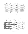
As represented schematically in FIG. 1, a microfluidic component 1 preferably comprises several microchannels 2 in which the fluid advances in parallel. Each microchannel 2 comprises reaction or detection zones 3 arranged for example at regular predetermined intervals. Reaction or detection zones 3 can in particular act as reaction chamber for the different steps of the biological protocol to be carried out, or they can act as mixing zone during progression of the fluid. Component 1 being previously empty, the fluid, or more particularly the fluid/gas interface, advances in microchannels 2 from upstream to downstream of component 1, i.e. from inlet to outlet of component 1, according to arrow F of FIG. 2 defining the direction of progression of the fluid.
Microchannels 2 also comprise passive valves 4, each arranged between two successive reaction or detection zones 3 and designed to temporarily impede the progression of the fluid in component 1. In the particular embodiment of FIGS. 1 to 3, component 1 for example comprises four microchannels 2, three series of reaction or detection zones 3 a, 3 b, 3 c and three series of intermediate passive valves 4 a, 4 b, 4 c. In FIGS. 1 to 3, passive valves 4 a, 4 b, 4 c are represented by hatchings and are defined for example by a non-wetting portion of microchannels 2 able to impede the fluid. The portions adjacent to passive valves 4 a, 4 b, 4 c are then wetting portions of microchannels 2 enabling flow of the fluid.
The U.S. Pat. No. 5,230,866 notably describes the operating principle of such a passive valve designed to control impeding of the fluid (represented in dark color in FIGS. 2 and 3) advancing due to the effect of an external pressure. A passive valve 4 only lets the fluid pass if the pressure difference between upstream and downstream of component 1 increases above a threshold value Ps proper to each passive valve 4 of component 1. Threshold value Ps generally depends on the geometric and wetting characteristics of the surface in contact with the fluid in passive valve 4. For example, operation of passive valve 4 is based on the principle of local change of capillary forces due to the abrupt variations of the surface properties, in particular the wettability or geometry, of microchannel 2.
A method for controlling the progression of the fluid in such a component 1 consists in increasing the pressure difference between upstream and downstream of component 1, so as to make the fluid advance from reaction or detection zones 3 to reaction or detection zones 3, the passive valves 4 of any one series, i.e. those arranged on the same vertical line in FIGS. 1 to 3, all being identical.
The method consists in increasing the pressure difference above threshold value Ps corresponding to passive valve 4 to be passed, and in then reducing the pressure difference to below corresponding threshold value Ps to make the fluid advance in the component.
However, imperfections on microchannels 2 of component 1 can lead to a passive valve 4 being passed before the others are passed. For example, as represented in FIG. 2, passive valve 4 a preceding second reaction or detection zone 3 b of second microchannel 2 has been passed before the others, notably because of the possible geometry and/or wettability imperfections of passive valve 4 a. Second reaction or detection zone 3 b is therefore filled before the other zones 3 b of the same series.
As represented in FIG. 3, microchannel 2 keeps this stagger throughout the progression of the fluid, in particular if all the other passive valves 4 a, 4 b, 4 c are operating normally as described above. Microchannel 2 corresponding to this passive valve 4 a will therefore be filled more quickly than the others. This leads in particular to synchronization problems in the progression of the fluid, which affects performance of the biological steps, and to difficulties in analysis and subsequently in using the results. In particular, in the case where several passive valves 4 are defective, an accumulation of negative effects is observed leading to aberrations in terms of use of the results.
To remedy these shortcomings, the documents US 2004/0109793 and WO 02/41995 and U.S. Pat. No. 6,296,020 each describe a device for distributing fluid in different channels of a component 1, as described above, from a common inlet chamber, with passage from one reaction or detection zone to another reaction or detection zone on each channel. Control of the fluid passage is performed by passive valves arranged on outlet from the reaction or detection zones. The passive valves are arranged in such a way as to have increasingly high threshold values Ps from upstream to downstream of the device.
As represented schematically in FIG. 4, passive valves 4 are arranged in four series with increasing threshold values Ps1 to Ps4 from upstream to downstream of component 1. The method for controlling the fluid progression in component 1 then consists in increasing the pressure difference between upstream and downstream of the component in the form of pressure plateaus. The biological protocol step corresponding to each reaction or detection zone 3 is performed at constant pressure during each pressure plateau. Applying a pressure difference per plateau, up to a value just below threshold value Ps of corresponding passive valve 4, enables passive valve 4 to be passed and the fluid to be stopped against the next passive valve 4. In the case of several series of passive valves 4 in parallel, as represented in FIGS. 1 to 3, applying a pressure difference per plateau enables the whole set of passive valves 4 of the same series to be passed at the same time and the fluid to be stopped against the following series of passive valves 4.
This particular method described above prevents a passive valve 4 from preferentially yielding to the pressure and directly filling a whole microchannel 2 of component 1. However it is technologically difficult to chain realization of a large number of passive valves 4 with increasing threshold values Ps from inlet to outlet of component 1. Furthermore, miniaturization of such a component 1 is limited by imperatives of size beyond which the viability of component 1 is questionable.
Furthermore, the document WO 01/04909 also describes another type of microfluidic device comprising a plurality of parallel branches each having a reaction cell and a capillary valve. A high-pressure gas pulse makes the fluid pass through the valves of all the branches of the device.
No known multichannel microfluidic component therefore enables the above-mentioned shortcomings to be remedied, and in particular the problem of passive valves preferentially yielding to pressure more particularly observed in the steps linked to detection or reaction zones 3, which are the seats of chemical, biochemical or biological reactions.
OBJECT OF THE INVENTION
The object of the invention is to remedy all the above-mentioned shortcomings and to achieve a method for controlling the progression of a fluid in a microchannel of a microfluidic component improving existing control methods and providing reliability in use of the component, while at the same time being easy to implement whatever the characteristics of the passive valves of the component.
The object of the invention is achieved by the appended claims, and more particularly by the fact that the pressure difference increase is controlled discontinuously in the form of enabling pulses and by the fact that the pressure difference is reduced to a zero value between two successive enabling pulses.
Such a method then does not depend exclusively on the threshold pressure of the passive valves and can be applied to an unlimited number of valves of the same series.
BRIEF DESCRIPTION OF THE DRAWINGS
Other advantages and features will become more clearly apparent from the following description of particular embodiments of the invention given as non-restrictive examples only and represented in the accompanying drawings, in which:
FIG. 1 schematically represents a microfluidic component designed to be controlled by a method for controlling the progression of a fluid according to the prior art.
FIGS. 2 and 3 schematically represent the component according to FIG. 1, inside which the fluid is flowing.
FIG. 4 is a plot representing the relative pressure versus time for a component controlled by a method according to the prior art.
FIG. 5 is a plot representing the relative pressure versus time for a component controlled by a method for controlling the progression of a fluid according to the invention.
FIGS. 6 to 8 schematically represent a component controlled by the method according to FIG. 5.
FIG. 9 schematically represent an automatic pressure control bench for implementation of the method according to FIGS. 5 to 8.
FIG. 10 schematically represents a microfluidic component designed to be controlled by a method for controlling the progression of a fluid according to an alternative embodiment.
DESCRIPTION OF PARTICULAR EMBODIMENTS
In the particular embodiment of FIGS. 5 to 9, microfluidic component 1 preferably comprises several microchannels 2 arranged in parallel, each microchannel 2 comprising an inlet connected to an inlet chamber 5 common to all the microchannels 2 (FIGS. 6 to 8). Component 1 is controlled in such a way that the fluid advances in synchronized manner in all the microchannels 2. Passive valves 4 and reaction or detection zones 3 of component 1 are preferably arranged in regular series spaced apart at regular preset intervals.
The method for controlling component 1 in particular enables passage of passive valves 4 of component 1 to be synchronized so that the passive valves allow the fluid to pass at the same time on all the microchannels 2 of component 1. The method controls the progression of the fluid according to the pressure difference between the inlet and outlet of component 1, i.e. between upstream and downstream of component 1.
Component 1 is preferably empty at the outset, the fluid being fed for example by an outlet pipe 8 coming from a tank 7 (FIG. 9). The common inlet chamber 5 is completely filled and the pressure is identical in all the microchannels 2. The method controls progression of the fluid, i.e. progression of the interface between the fluid and the gas initially contained in component 1, by increasing the pressure difference between the inlet of component 1, defined by inlet chamber 5 in FIGS. 6 to 8, and the outlet of component 1, defined by the end of microchannels 2 in FIGS. 6 to 8.
In FIG. 5, the time scale and the scale of the relative pressure values have not been respected for the sake of clarity and legibility of the graph. The method consists in controlling the increase of the pressure difference between upstream and downstream of component 1 in discontinuous manner. The increase of the pressure difference pressure is controlled in the form of enabling pulses Pd unblocking passive valves 4 and of fluid advance periods Pav1, Pav2.
Each enabling pulse Pd corresponds to an abrupt variation of short time duration of the pressure difference between upstream and downstream of component 1. This variation passes via a maximum value Psup and drops back down to a level preferably close to zero. This value Psup is greater than the maximum threshold value Ps of all the threshold values Ps of passive valves 4 of component 1.
As represented in FIG. 5, each enabling pulse Pd presents a value Psup that is preferably very high compared with threshold value Ps of passive valves 4, in the case where passive valves 4 are all identical. In the case where passive valves 4 present different threshold values Ps due to their different geometric and/or wettability characteristics, the value Psup of enabling pulses Pd is then much higher than the maximum threshold value Ps of passive valve 4 of component 1 having the highest threshold value Ps of all the passive valves 4.
A continuous intermediate fluid advance period Pav1, taking place between the enabling pulses Pd, is designed to make the fluid advance to fill corresponding reaction or detection zones 3 of component 1. Each intermediate fluid advance period Pav1 is achieved by a pressure difference, preferably much smaller than the value Psup of an enabling pulse Pd and during a potentially much longer time.
In the particular embodiment of FIG. 5, the method for controlling component 1 comprises for example at least one compulsory intermediate fluid advance period Pav1 applied after an enabling pulse Pd, and at least one optional additional fluid advance period Pav2 applied just before an enabling pulse Pd, to ensure that microchannels 2 are completely filled, until the fluid is impeded by the corresponding passive valves 4.
During each fluid advance period Pav1, Pav2, the pressure difference applied between inlet and outlet of component 1 has a maximum base value Pb, lower than the minimum threshold value of passive valves 4 of component 1. The continuous intermediate fluid advance periods Pav1 must preferably bring the fluid up to contact with the following passive valves 4 to avoid application of the additional fluid advance periods Pav2.
A step of the biological protocol associated with reaction or detection zones 3 of component 1 has to be performed at zero pressure difference between a continuous intermediate fluid advance period Pav1 and possibly an additional fluid advance period Pav2. Should a fluid advance period Pav1 be conserved during the step of the associated biological protocol, certain passive valves 4 could in fact be preferentially passed, notably on account of the duration of the biological protocols carried out in reaction or detection zones 3. This would then give rise to errors as to the reliability of analysis, in particular on account of the loss of a part of the reaction volume. Such a zero pressure difference, as described above, thereby prevents any loss of integrity of the reaction volume during the biological protocol step performed in the corresponding reaction or detection zones 3.
For example, experimental resistance tests of passive valves 4 under pressure were performed with a biological buffer formed by the following elements: Tris pH8.5 40 mM, DMSO 15% vol., KCl 80 mM, MgCl2 12 mM, BSA 0.13 mg/mL. This buffer which is conventionally used in biology was injected into a microfluidic component comprising reaction or detection zones and passive valves with abrupt enlargement, with an opening diameter of 30 μm and a triggering pressure of around 70 mbar specific to this buffer. The component is regulated in temperature to 41° C. The filling pressure of the component is close to 30 mbar and this pressure is applied until the fluid is impeded on the enlargement valves.
Two experiments were then performed, in accordance with the table below, on the one hand bringing the pressure down to zero (first line of the table below) and on the other hand adjusting the pressure to its filling value (second line of the table below). The time (second column of the table below) is measured until the fluid is seen to appear in the following reaction or detection zone of the component, a sign that the fluid has passed the corresponding passive valve.
Time until the fluid passes
Zero pressure >1 hour (no valves passed during this time)
Pressure of about 30 mbar <1 minute
The table above gives the values of the time after which the fluid passed into the next reaction or detection zone of the component. It is therefore apparent from the above table that the time is much more than one hour when no pressure difference is applied in the component. The passive valves on the other hand only hold up the fluid for less than one minute when the pressure difference is kept at its filling value. The very great importance of the step described above, consisting in adjusting the pressure difference to a zero value, is therefore apparent from the above table, in order to optimize performance of the biological protocol steps in the reaction or detection zones of the component.
The control method will be described in even greater detail with regard to FIGS. 5 to 8. In FIGS. 6 to 8, component 1 for example comprises an inlet chamber 5, via which the fluid is inlet, common to all the inlets of microchannels 2. For example, a reaction or detection zone 3 has a volume of about 0.3 μl, with a depth of about 200 μm. The fluid considered in component 1 being water and all the passive valves 4 of component 1 being identical, a passive valve 4 is defined for example by an abrupt change of geometry of the associated microchannel 2. For example, a microchannel 2 presents a general diameter of about 500 μm and a narrowed diameter of about 100 μm defining passive valve 4. A passive valve 4 presents a threshold value Ps comprised for example between 5 mbar and 2 bar. The threshold value Ps of passive valves 4 is preferably about 20 mbar.
In the particular embodiment of FIGS. 6 to 8, control of the increase of the pressure difference between inlet and outlet of component 1 is performed upstream from component 1. Inlet chamber 5 is for example connected to a control device of the external pressure enabling the pressure difference between upstream and downstream of component 1 to be implemented (FIG. 9).
In FIG. 5, the first step of the method consists in applying a continuous intermediate fluid advance period Pav1, at base value Pb, between the times t0 and t1. This pressure difference Pb enables the first series of reaction or detection zones 3 a to be filled, until the fluid is stopped by the first series of passive valves 4 a, as represented in FIG. 6.
Between the times t1 and t2, the pressure difference must be zero in order to stop progression of the fluid. The biological protocol step corresponding to the first reaction or detection zones 3 a is then performed preferably simultaneously in all the reaction or detection zones 3 a of the first series. The biological protocol step performed in each reaction or detection zone 3 a of one and the same series may be different depending on microchannels 2.
Between the times t2 and t3, an additional fluid advance period Pav2 may be applied, at base value Pb, just before enabling pulse Pd, in the case where the fluid has not completely filled microchannels 2 up to passive valves 4 a following reaction or detection zones 3 a.
Between the times t3 and t4, corresponding to a time period T1, a first enabling pulse Pd is applied in component 1. The value Psup of enabling pulse Pd is preferably very high compared with the threshold value Ps of passive valves 4 a to 4 c. The value Psup is for example comprised between 1 bar and 2.5 bar. The value Psup is preferably about 2 bar. The time T1 of enabling pulse Pd is very short and comprised for example between 100 ms and 500 ms. The time T1 is preferably about 350 ms.
In a general manner, the value Psup of enabling pulse Pd must allow systematic and preferably synchronized passage of all the passive valves 4 of the same series. Time period T1 of the enabling pulse Pd must be sufficiently long to enable this passage, but sufficiently short for the fluid to just have passed the corresponding passive valves 4 without completely filling the next reaction or detection zones 3.
Furthermore, the ratio of the value Psup of an enabling pulse Pd over the maximum threshold value Ps of passive valves 4 is greater than 1.25 and preferably comprised between 1.25 and 200. The ratio is preferably about 100 for a threshold value Ps of about 20 mbar and a value Psup of enabling pulse Pd of about 2 bar.
At time t4, corresponding to the end of period T1, the pressure difference is preferably adjusted to zero, so that enabling pulse Pd presents a zero lower value. Between times t4 and t5 corresponding to a time period T2, the pressure difference remains equal to zero. The time period T2 must be sufficiently long for the pressure to drop back completely to stop progression of the fluid. Time period T2 is for example about 500 ms.
In FIG. 5, the step of the control method described above is optional. It is possible for enabling pulse Pd to present a lower value equal to base value Pb so as to continue the progression of the fluid and to perform filling of the next reaction or detection zones 3 b immediately after enabling pulse Pd.
Between times t5 and t6 corresponding to a time period T3, a continuous intermediate fluid advance period Pav1 is carried out. The object of this continuous intermediate fluid advance period Pav1 is to fill the next reaction or detection zones 3 b (FIG. 7), i.e. those of the second series in the particular embodiment of component 1 represented in FIGS. 6 to 8.
In a general manner, each continuous intermediate fluid advance period Pav1 presents a sufficient maximum value to make the fluid advance, a value which is preferably equal to base value Pb and always lower than the minimum threshold value Ps of the set of passive valves 4. For example, the maximum base value Pb of a continuous intermediate fluid advance period Pav1 is comprised between 5 mbar and 100 mbar. Base value Pb is preferably about 15 mbar.
In FIG. 5, at time t6, continuous intermediate fluid advance period Pav1 presents a zero minimum value so as to stop the progression of the fluid in microchannels 2. Time duration T3 of a continuous intermediate fluid advance period Pav1 is for example about 60 s.
In a general manner, time period T3 of a continuous intermediate fluid advance period Pav1 must be sufficiently long for the fluid to be able to completely fill the corresponding reaction or detection zones 3 and to stop on the corresponding passive valves 4 for all the microchannels 2.
Furthermore, the ratio of time duration T1 of an enabling pulse Pd over time duration T3 of a continuous intermediate fluid advance period Pav1 is for example comprised between 0.1% and 1%. The ratio is preferably about 0.58%, for a time period T1 of about 350 ms and a time period T3 of about 60 s. In a general manner, time periods T1 and T3 are in particular chosen according to the pressure and geometry of component 1.
Furthermore, the time duration T3 of a continuous intermediate fluid advance period Pav1 can be determined according to signals supplied by at least one filling detector associated with microchannels 2 of component 1. The principle of the filling detector is based notably on detection of a change of the physical properties between the gas initially contained in microchannels 2 and the fluid.
For example, an optical filling detector can be used, arranged as an emitter and a receiver on the two sides of each microchannel 2. It is then possible to measure a change of the optical properties, in particular by determining the change from gas to fluid.
In another embodiment example, an electric filling detector can be used, two electrodes being arranged at the level of each passive valve 4. As the fluids used are conducting, the presence of the fluid can be detected by an abrupt change of the electrical conductivity between the two electrodes.
In FIG. 5, between times t6 and t7 corresponding to a time period T4, the step or steps of the biological protocol corresponding to the second series of reaction or detection zones 3 b are performed (FIG. 7). The pressure difference must absolutely be zero between upstream and downstream of component 1, so as on the one hand to ensure a good synchronization of the progression of the fluid in all the microchannels 2, and on the other hand to prevent any loss of integrity of the reaction volume during the biological protocol step being performed. If fluid advance period Pav1 is kept during the associated biological protocol steps, certain passive valves 4 could preferentially yield to the pressure, as described above. This would then lead to losses of a part of the reaction volume.
Such a zero pressure difference, as described above, thereby prevents any loss of integrity of the reaction volume during the biological protocol step performed in the corresponding reaction or detection zones 3 b. Time period T4 is for example comprised between 60 s and 3600 s. Time period T4 is preferably about 1800 s.
At time t7, an increase of the pressure difference is applied in microchannels 2 until base value Pb is reached. Between times t7 and t8 corresponding to a time period T5, additional fluid advance period Pav2 enables filling of microchannels 2 to be completed, until second series of passive valves 4 b are reached. This step applies only when microchannels 2 are not completely filled, after continuous intermediate fluid advance period Pav1 carried out between times t5 and t6. Time duration T5 of an additional fluid advance period Pav2 is for example about 60 s.
In a general manner, time period T5 has to be sufficiently long for fluid to be able to stop on corresponding passive valves 4 in all the microchannels 2. Time period T5 of an additional fluid advance period Pav2 may further be determined according to signals supplied by at least one filling detector associated with microchannels 2 of component 1, as described above for determination of time period T3.
In FIG. 5, between times t8 and t9 corresponding to a time period T6, a new enabling pulse Pd is again applied in component 1 in particular in order to pass all the passive valves 4 b of the second series in synchronized manner, as represented in FIG. 8.
Between times t9 and t10, a possible step of returning the pressure difference to zero can be applied. Then, between times t10 and t11, a new continuous intermediate fluid advance period Pav1 can be performed to fill the third series of reaction or detection zones 3 c, as represented in FIG. 8.
The control method thus continues in this way all along microchannels 2 of component 1, with alternation between enabling pulses Pd to pass any subsequent passive valves 4 (not shown), fluid advance periods Pav1 and Pav2 to fill any subsequent reaction or detection zones 3 (not shown), and steps of returning the pressure difference to zero between two successive enabling pulses Pd, to perform the steps of the biological protocol.
Such a control method of a microfluidic component 1 thereby enables the progression of the fluid to be controlled, in particular in synchronized manner, on all of the microchannels 2 of component 1, while at the same time ensuring that the steps of the biological protocol are performed optimally due to zero resetting of the pressure difference during the method. The method is applicable whatever the characteristics of passive valves 4, whether they be identical or not, due to the preferably very high value Psup of enabling pulses Pd compared with the maximum threshold value Ps of all the passive valves 4.
This results in reliability of the analyses performed in reaction or detection zones 3 and reliability of general implementation of component 1. The influence of possible imperfections of microchannels 2 is eliminated.
In a general manner, the method for controlling the progression of the fluid in component 1, as described above, can be applied to a microfluidic component comprising a single microchannel 2. The method is then designed in particular to ensure systematic passage of a passive valve 4, whatever its characteristics and whatever the imperfections it may present, and to ensure that the conditions for performing the biological protocol steps are optimal.
In FIG. 9, a particular embodiment of an automatic pressure control bench 6 for implementation of the control method described above is represented. Bench 6 in particular enables the increase of the pressure difference between upstream and downstream of microfluidic component 1 to be controlled. Automatic pressure control bench 6 comprises a fluid tank 7 comprising an outlet 8 connected for example to inlet chamber 5 of component 1 (not shown in FIG. 9 for reasons of clarity) and an inlet 9 connected to a high pressure source 10, for example up to 4 bar.
High pressure source 10 comprises three circuits 11 a, 11 b, 11 c in parallel each respectively equipped with a pressure-reducing gauge 12 a, 12 b, 12 c and an electropneumatic valve 13 a, 13 b, 13 c. Inlet 9 of tank 7 is also connected to atmospheric pressure Patm by a circuit 11 d comprising a fourth electropneumatic valve 13 d, circuit 11 d being connected to the three circuits 11 a, 11 b, 11 c in parallel. A pressure sensor 14 is connected to inlet 9 of tank 7 and to the four circuits 11 a, 11 b, 11 c, 11 d.
Such an automatic pressure control bench 6 in particular enables the method for controlling a microfluidic component as described above to be implemented, and pressure pulses as short as 100 ms to be controlled. Furthermore, electropneumatic valves 13 a to 13 d can be controlled by relays, themselves controlled by a micro-computer. This results in precise and calibrated pressure sequences being performed on inlet of the associated microfluidic component.
Moreover, time period T1 of an enabling pulse and time period T3 of a continuous intermediate fluid advance period Pav1 are chosen according to the characteristics of component 1, and more particularly according to the gas volume present in tank 7 of automatic pressure control bench 6, as described above.
The invention is not limited to the different embodiments described above. Passive valves 4 of component 1 can have different threshold values Ps from one another and can also have different geometrical characteristics, depending on their arrangements in microchannels 2.
Fluid advance periods Pav1 and Pav2, respectively during time periods T3 and T5, may oscillate between base value Pb and zero pressure difference value.
The number of microchannels 2, of reaction or detection zones 3 and of passive valves 4 is non-restrictive. It depends on the general size of component 1 to be controlled and/or on the biological protocols to be carried out.
A reaction or detection zone 3 of component 1 can further be defined by a portion of corresponding microchannel 2. Reaction or detection zone 3 then has the same dimensions as microchannel 2, but constitutes a particular portion thereof.
In another alternative embodiment of the method for controlling the progression of the fluid in component 1 shown in FIG. 10, control of the increase of pressure difference between upstream and downstream of microfluidic component 1 can be performed downstream from microfluidic component 1. For example, movement of the fluid can take place by negative pressure by placing for example a vacuum source at the outlet of component 1. Microchannels 2 of component 1 then each comprise an outlet connected the vacuum source, which then defines an outlet chamber 15 common to all the microchannels 2.
An optional additional period of returning the pressure difference to zero can be performed between each additional fluid advance period Pav2 and each enabling pulse Pd (FIG. 5) in order to impede the progression of the fluid just before enabling pulse Pd. This additional period can for example have a duration of about 500 ms.

Claims (13)

1. A method for controlling the progression of a fluid from inlet to an outlet of a microfluidic component comprising:
providing the microfluidic component with a microchannel comprising a plurality of successive reaction or detection zones connected in series, a plurality of passive valves connected in series with the reaction or detection zones wherein each two successive reaction or detection zones in the microchannel are separated by one passive valve from the inlet to the outlet;
applying a plurality of pressure pulses comprising a first step at a first pressure difference between the inlet and the outlet of the microfluidic component during a first period, wherein the first pressure difference is higher than a threshold value for the passive valve so as to achieve progression of the fluid via the successive passive valves; and
applying a zero pressure difference between the inlet and the outlet of the component between two successive pressure pulses so as to stop progression of the fluid between two successive passive valves.
2. The method according to claim 1, wherein the duration of the pulse is from 100 ms to 500 ms.
3. The method according to claim 1, wherein the pressure difference is performed upstream from the microfluidic component.
4. The method according to claim 3, wherein the microfluidic component comprises a plurality of microchannels arranged in parallel, each microchannel comprising an inlet connected to a common inlet chamber, wherein the common inlet chamber is configured to apply an identical pressure in all the microchannels.
5. The method according to claim 1, wherein the pressure difference is performed downstream from the microfluidic component.
6. The method according to claim 5, wherein the microfluidic component comprises a plurality of microchannels arranged in parallel, each microchannel comprising an outlet connected to a common outlet chamber, wherein the common outlet chamber is configured to apply an identical pressure in all the microchannels.
7. The method according to claim 1, wherein the first pressure difference value of each pulse is higher than a maximum threshold value of the passive valves.
8. The method according to claim 7, wherein the ratio of the first pressure difference value of the pulse over the maximum threshold value of the passive valves is greater than 1.25.
9. The method according to claim 1, wherein the pulse comprises a second step at a second difference pressure value lower than a minimum threshold value of the passive valves.
10. The method according to claim 9, wherein the zero pressure difference is applied immediately after the second step and before the next pulse at the first difference pressure.
11. The method according to claim 9, wherein the second difference value is equal to 15 mbar.
12. The method according to claim 9, wherein the pressure pulse comprises a third step at a third difference pressure value lower than a minimum threshold value of the passive valves, the second step and the third step separated by the first step.
13. The method according to claim 12, wherein the duration of the second step or the third step is defined according to a signal supplied by one filling detector associated with each microchannel of the component.
US12/223,059 2006-02-16 2007-02-15 Method for controlling the progression of a fluid in a microfluidic component Expired - Fee Related US8215338B2 (en)

Applications Claiming Priority (3)

Application Number Priority Date Filing Date Title
FR0601375 2006-02-16
FR0601375A FR2897282B1 (en) 2006-02-16 2006-02-16 METHOD FOR CONTROLLING THE ADVANCE OF A LIQUID IN AN ANTI-MICROFLUIDIC COMPOUND
PCT/FR2007/000275 WO2007093712A1 (en) 2006-02-16 2007-02-15 Method for controlling the progress of a liquid in a microfluid component

Publications (2)

Publication Number Publication Date
US20080314454A1 US20080314454A1 (en) 2008-12-25
US8215338B2 true US8215338B2 (en) 2012-07-10

Family

ID=37056531

Family Applications (1)

Application Number Title Priority Date Filing Date
US12/223,059 Expired - Fee Related US8215338B2 (en) 2006-02-16 2007-02-15 Method for controlling the progression of a fluid in a microfluidic component

Country Status (7)

Country Link
US (1) US8215338B2 (en)
EP (1) EP1984110B1 (en)
JP (1) JP5031776B2 (en)
CN (1) CN101384354B (en)
AT (1) ATE529184T1 (en)
FR (1) FR2897282B1 (en)
WO (1) WO2007093712A1 (en)

Cited By (5)

* Cited by examiner, † Cited by third party
Publication number Priority date Publication date Assignee Title
US20100093016A1 (en) * 2008-10-10 2010-04-15 Cytyc Corporation Microfluidic apparatus and method for preparing cytological specimens
US20150196909A1 (en) * 2014-01-15 2015-07-16 Imec Vzw Microstructured Micropillar Arrays for Controllable Filling of a Capillary Pump
US20180311627A1 (en) * 2015-06-29 2018-11-01 Imec Vzw Valve-Less Mixing Method and Mixing Device
CN112512688A (en) * 2018-04-30 2021-03-16 蛋白流控技术公司 Valveless fluid switching flow chip and application thereof
EP4089161A1 (en) * 2021-05-12 2022-11-16 ibidi GmbH Substrate for testing samples and system comprising the substrate

Families Citing this family (16)

* Cited by examiner, † Cited by third party
Publication number Priority date Publication date Assignee Title
JP4942662B2 (en) * 2005-10-28 2012-05-30 アークレイ株式会社 Liquid feeding method and cartridge used therefor
WO2008113112A1 (en) * 2007-03-16 2008-09-25 Cleveland Biosensors Pty Ltd Stop structure for microfluidic device
FR2938063B1 (en) 2008-11-05 2014-09-19 Commissariat Energie Atomique DEVICE FOR PREPARING AND / OR PROCESSING A BIOLOGICAL SAMPLE
GB0912509D0 (en) * 2009-07-17 2009-08-26 Norchip As A microfabricated device for metering an analyte
CN102527306B (en) * 2010-12-28 2014-01-29 中国科学院化学研究所 Array type continuously-flowing microfluidic chip device and manufacture method and application thereof
US10384209B2 (en) 2011-09-15 2019-08-20 The Chinese University Of Hong Kong Microfluidic platform and method for controlling the same
US10730046B2 (en) * 2014-10-31 2020-08-04 University Of Iowa Research Foundation Fluid handling systems for application of fluid shear stress to a fluid sample
FR3035009B1 (en) 2015-04-20 2020-02-07 Commissariat A L'energie Atomique Et Aux Energies Alternatives MICROFLUIDIC DEVICE FOR CONTROLLING THE FLOW OF A FLUID
FR3064621B1 (en) * 2017-04-03 2022-02-18 Fluigent MICROFLUIDIC DEVICE
EP3615220A4 (en) 2017-04-28 2020-12-30 Neofluidics, LLC Fluidic devices with reaction wells and uses thereof
EP3665262A4 (en) 2017-08-09 2021-09-01 Neofluidics, LLC Devices and methods for bioassay
CN108051598B (en) * 2017-10-19 2020-01-24 广州市第一人民医院 Ready-to-use liquid drop biological analysis chip capable of being preloaded with reagent and application thereof
WO2019094775A1 (en) 2017-11-10 2019-05-16 Neofluidics, Llc Integrated fluidic circuit and device for droplet manipulation and methods thereof
CA3158313A1 (en) * 2018-10-26 2020-04-30 Unchained Labs Fluidic devices with reaction wells and constriction channels and uses thereof
FR3116215B1 (en) * 2020-11-17 2024-03-29 Magia Diagnostics CARTRIDGE COMPRISING A PLURALITY OF ANALYSIS CHAMBERS TO RECEIVE A BIOLOGICAL LIQUID
CN113952892B (en) * 2021-12-03 2023-10-10 花安堂生物科技集团有限公司 Method for preparing suspension micro-droplets by utilizing negative pressure

Citations (13)

* Cited by examiner, † Cited by third party
Publication number Priority date Publication date Assignee Title
US4390885A (en) * 1981-06-26 1983-06-28 Texas Instruments Incorporated Apparatus and method for fluid transfer
US5230866A (en) 1991-03-01 1993-07-27 Biotrack, Inc. Capillary stop-flow junction having improved stability against accidental fluid flow
US5980704A (en) * 1995-06-07 1999-11-09 David Sarnoff Research Center Inc. Method and system for inhibiting cross-contamination in fluids of combinatorial chemistry device
WO2000030751A2 (en) * 1998-11-25 2000-06-02 Affymetrix, Inc. Microplate sample and reagent loading system
WO2001004909A1 (en) 1999-07-09 2001-01-18 Orchid Biosciences, Inc. Fluid delivery system for a microfluidic device using a pressure pulse
US6296020B1 (en) 1998-10-13 2001-10-02 Biomicro Systems, Inc. Fluid circuit components based upon passive fluid dynamics
WO2002041995A1 (en) 2000-11-27 2002-05-30 Pyrosequencing Ab Microfluidic flow control
US20030082081A1 (en) * 2001-10-24 2003-05-01 Commissariat A L'energie Atomique Device for parallel and synchronous injection for sequential injection of different reagents
US20030190608A1 (en) 1999-11-12 2003-10-09 Gary Blackburn Microfluidic devices comprising biochannels
WO2003098218A1 (en) 2002-05-10 2003-11-27 Biomicro Systems, Inc. Multi-channel microfluidic system design with balanced fluid flow distribution
US20040109793A1 (en) 2002-02-07 2004-06-10 Mcneely Michael R Three-dimensional microfluidics incorporating passive fluid control structures
US7041068B2 (en) * 2001-06-12 2006-05-09 Pelikan Technologies, Inc. Sampling module device and method
US20070157973A1 (en) * 2000-02-23 2007-07-12 Caliper Life Sciences, Inc. Multi-reservoir pressure control system

Family Cites Families (4)

* Cited by examiner, † Cited by third party
Publication number Priority date Publication date Assignee Title
DE10022398B4 (en) * 2000-04-28 2011-03-17 Eppendorf Ag Gas cushion micro-dosing system
WO2002068821A2 (en) * 2001-02-28 2002-09-06 Lightwave Microsystems Corporation Microfluidic control using dieletric pumping
NO20023398D0 (en) * 2002-07-15 2002-07-15 Osmotex As Apparatus and method for transporting liquid through materials
JP4701758B2 (en) * 2005-03-10 2011-06-15 凸版印刷株式会社 Micro channel chip

Patent Citations (13)

* Cited by examiner, † Cited by third party
Publication number Priority date Publication date Assignee Title
US4390885A (en) * 1981-06-26 1983-06-28 Texas Instruments Incorporated Apparatus and method for fluid transfer
US5230866A (en) 1991-03-01 1993-07-27 Biotrack, Inc. Capillary stop-flow junction having improved stability against accidental fluid flow
US5980704A (en) * 1995-06-07 1999-11-09 David Sarnoff Research Center Inc. Method and system for inhibiting cross-contamination in fluids of combinatorial chemistry device
US6296020B1 (en) 1998-10-13 2001-10-02 Biomicro Systems, Inc. Fluid circuit components based upon passive fluid dynamics
WO2000030751A2 (en) * 1998-11-25 2000-06-02 Affymetrix, Inc. Microplate sample and reagent loading system
WO2001004909A1 (en) 1999-07-09 2001-01-18 Orchid Biosciences, Inc. Fluid delivery system for a microfluidic device using a pressure pulse
US20030190608A1 (en) 1999-11-12 2003-10-09 Gary Blackburn Microfluidic devices comprising biochannels
US20070157973A1 (en) * 2000-02-23 2007-07-12 Caliper Life Sciences, Inc. Multi-reservoir pressure control system
WO2002041995A1 (en) 2000-11-27 2002-05-30 Pyrosequencing Ab Microfluidic flow control
US7041068B2 (en) * 2001-06-12 2006-05-09 Pelikan Technologies, Inc. Sampling module device and method
US20030082081A1 (en) * 2001-10-24 2003-05-01 Commissariat A L'energie Atomique Device for parallel and synchronous injection for sequential injection of different reagents
US20040109793A1 (en) 2002-02-07 2004-06-10 Mcneely Michael R Three-dimensional microfluidics incorporating passive fluid control structures
WO2003098218A1 (en) 2002-05-10 2003-11-27 Biomicro Systems, Inc. Multi-channel microfluidic system design with balanced fluid flow distribution

Cited By (11)

* Cited by examiner, † Cited by third party
Publication number Priority date Publication date Assignee Title
US20100093016A1 (en) * 2008-10-10 2010-04-15 Cytyc Corporation Microfluidic apparatus and method for preparing cytological specimens
US8460619B2 (en) 2008-10-10 2013-06-11 Cytyc Corporation Microfluidic apparatus and method for preparing cytological specimens
US20150196909A1 (en) * 2014-01-15 2015-07-16 Imec Vzw Microstructured Micropillar Arrays for Controllable Filling of a Capillary Pump
US9174211B2 (en) * 2014-01-15 2015-11-03 Imec Vzw Microstructured micropillar arrays for controllable filling of a capillary pump
US20180311627A1 (en) * 2015-06-29 2018-11-01 Imec Vzw Valve-Less Mixing Method and Mixing Device
US10537862B2 (en) * 2015-06-29 2020-01-21 Imec Vzw Valve-less mixing method and mixing device
CN112512688A (en) * 2018-04-30 2021-03-16 蛋白流控技术公司 Valveless fluid switching flow chip and application thereof
EP3787795A4 (en) * 2018-04-30 2022-01-26 Protein Fluidics, Inc. Valveless fluidic switching flowchip and uses thereof
US11376589B2 (en) 2018-04-30 2022-07-05 Protein Fluidics, Inc. Valveless fluidic switching flowchip and uses thereof
US11839873B2 (en) 2018-04-30 2023-12-12 Protein Fluidics, Inc. Valveless fluidic switching flowchip and uses thereof
EP4089161A1 (en) * 2021-05-12 2022-11-16 ibidi GmbH Substrate for testing samples and system comprising the substrate

Also Published As

Publication number Publication date
US20080314454A1 (en) 2008-12-25
EP1984110B1 (en) 2011-10-19
EP1984110A1 (en) 2008-10-29
FR2897282A1 (en) 2007-08-17
FR2897282B1 (en) 2008-05-30
WO2007093712A1 (en) 2007-08-23
CN101384354B (en) 2013-09-18
ATE529184T1 (en) 2011-11-15
JP5031776B2 (en) 2012-09-26
JP2009526642A (en) 2009-07-23
CN101384354A (en) 2009-03-11

Similar Documents

Publication Publication Date Title
US8215338B2 (en) Method for controlling the progression of a fluid in a microfluidic component
JP5788515B2 (en) System and method for fast pulse gas delivery
US6883957B2 (en) On chip dilution system
WO2009109868A1 (en) Microfluidic apparatus and method for measuring thermo-physical properties of a reservoir fluid
EP2659977B1 (en) Microfluidics system for sequencing
US10378663B2 (en) Pinch flow regulator
JP2011524008A5 (en)
JP6676036B2 (en) Method for fusing or contacting a reactant with a reagent droplet in a microfluidic or millifluidic device
RU2729204C2 (en) Improving balancing flow or relative to it
US8671733B2 (en) Calibration procedure considering gas solubility
EP3993905B1 (en) Microfluidic device and method for processing and aliquoting a sample liquid
US20080112849A1 (en) Micro total analysis chip and micro total analysis system
JP2008122233A (en) Micro-integrated analysis chip and micro-integrated analysis system
US6447581B2 (en) Gas flow switching device
WO2010115907A1 (en) Sample storage in microfluidics devices
US20210237058A1 (en) Microfluidic devices to detect fluid priming
KR20110048241A (en) Method and Apparatus for determining characteristics of fluid
US11596943B2 (en) Multi hole inlet structure
JP2012150032A (en) Column system and method for measuring component using column system
Liu et al. A closed-loop intelligent control strategy for precise non-contact liquid dispensing
JP2021126650A (en) Liquid dispensing system for microfluidic sample carrier, microfluidic sample carrier sealing system including such liquid dispensing system, and method of dispensing sealing liquid using the same
US20220146544A1 (en) Normalizing fluid in a fluidic device
US20050223821A1 (en) Sampling system
EP3550298A1 (en) Device for the distribution of sample and carrier liquid across a micro-fabricated separation channel
EP2416882A1 (en) Sample storage in microfluidics devices

Legal Events

Date Code Title Description
AS Assignment

Owner name: COMMISSARIAT A L'ENERGIE ATOMIQUE, FRANCE

Free format text: ASSIGNMENT OF ASSIGNORS INTEREST;ASSIGNORS:DELATTRE, CYRIL;CHARLES, RAYMOND;POUTEAU, PATRICK;REEL/FRAME:021304/0266

Effective date: 20080710

Owner name: BIO MERIEUX, FRANCE

Free format text: ASSIGNMENT OF ASSIGNORS INTEREST;ASSIGNORS:DELATTRE, CYRIL;CHARLES, RAYMOND;POUTEAU, PATRICK;REEL/FRAME:021304/0266

Effective date: 20080710

STCF Information on status: patent grant

Free format text: PATENTED CASE

FPAY Fee payment

Year of fee payment: 4

FEPP Fee payment procedure

Free format text: MAINTENANCE FEE REMINDER MAILED (ORIGINAL EVENT CODE: REM.); ENTITY STATUS OF PATENT OWNER: LARGE ENTITY

LAPS Lapse for failure to pay maintenance fees

Free format text: PATENT EXPIRED FOR FAILURE TO PAY MAINTENANCE FEES (ORIGINAL EVENT CODE: EXP.); ENTITY STATUS OF PATENT OWNER: LARGE ENTITY

STCH Information on status: patent discontinuation

Free format text: PATENT EXPIRED DUE TO NONPAYMENT OF MAINTENANCE FEES UNDER 37 CFR 1.362

FP Lapsed due to failure to pay maintenance fee

Effective date: 20200710