US8208623B2 - Echo processing method and device - Google Patents
Echo processing method and device Download PDFInfo
- Publication number
- US8208623B2 US8208623B2 US11/863,536 US86353607A US8208623B2 US 8208623 B2 US8208623 B2 US 8208623B2 US 86353607 A US86353607 A US 86353607A US 8208623 B2 US8208623 B2 US 8208623B2
- Authority
- US
- United States
- Prior art keywords
- signal
- frequency band
- echo
- specified frequency
- near end
- Prior art date
- Legal status (The legal status is an assumption and is not a legal conclusion. Google has not performed a legal analysis and makes no representation as to the accuracy of the status listed.)
- Expired - Fee Related, expires
Links
- 238000003672 processing method Methods 0.000 title claims abstract description 27
- 238000001228 spectrum Methods 0.000 claims description 43
- 238000012545 processing Methods 0.000 claims description 11
- 230000000694 effects Effects 0.000 abstract description 6
- 238000001514 detection method Methods 0.000 description 20
- 238000010586 diagram Methods 0.000 description 12
- 230000003044 adaptive effect Effects 0.000 description 7
- 238000004891 communication Methods 0.000 description 6
- 230000007423 decrease Effects 0.000 description 3
- 238000004458 analytical method Methods 0.000 description 2
- 238000004364 calculation method Methods 0.000 description 2
- 238000006243 chemical reaction Methods 0.000 description 2
- 238000012937 correction Methods 0.000 description 2
- 238000000034 method Methods 0.000 description 2
- 238000012544 monitoring process Methods 0.000 description 2
- 230000001629 suppression Effects 0.000 description 2
- 230000006866 deterioration Effects 0.000 description 1
- 238000005516 engineering process Methods 0.000 description 1
- 230000001939 inductive effect Effects 0.000 description 1
- 238000012986 modification Methods 0.000 description 1
- 230000004048 modification Effects 0.000 description 1
- 230000004044 response Effects 0.000 description 1
- 238000012549 training Methods 0.000 description 1
Images


Classifications
-
- H—ELECTRICITY
- H04—ELECTRIC COMMUNICATION TECHNIQUE
- H04B—TRANSMISSION
- H04B3/00—Line transmission systems
- H04B3/02—Details
- H04B3/20—Reducing echo effects or singing; Opening or closing transmitting path; Conditioning for transmission in one direction or the other
- H04B3/23—Reducing echo effects or singing; Opening or closing transmitting path; Conditioning for transmission in one direction or the other using a replica of transmitted signal in the time domain, e.g. echo cancellers
Definitions
- the present invention relates to an echo processing method and device, and in particular to a method and device for processing a line echo which occurs in a converter between a digital line and an analog line in a private branch exchange (PBX), a conference device, and the like.
- PBX private branch exchange
- FIG. 10 shows a 2-wire/4-wire converter used for such a conversion.
- a near end signal from a digital line of an extension line, VoIP, or the like on a transmitting side turns around to a receiving side as a line echo LE as shown in FIG. 10 .
- a near end receiver unintentionally hears a voice of a near end caller with a time delay due to the line echo LE, which leads to interference of the conversation.
- an echo canceller As a technology for cancelling such a line echo, an echo canceller has been well known.
- One example of the echo canceller is mentioned in the patent document 1.
- a reference signal transmitting signal Ts
- an adaptive filter 5 _ 1 composed of a digital filter
- an estimated echo signal (pseudo echo signal) Ec is generated, so that an echo component is removed by subtracting the estimated echo signal Ec from a receiving signal Rs in a subtractor 5 _ 2 .
- filter coefficients of the adaptive filter 5 _ 1 are adaptively updated so that the error signal Es may become small (learning of propagation characteristic).
- FIG. 12 As an echo detection system for detecting such an echo section, various systems have been proposed, and the typical arrangement thereof is shown in FIG. 12 .
- an echo detector 6 is added to the echo canceller 5 .
- the transmitting signal (reference signal) Ts, the receiving signal Rs, and the error signal Es of the echo canceller 5 are acoustically analyzed/compared as shown in the following (1)-(3), so that a detection result Dr of the echo section is outputted, only in which the echo canceller 5 is driven:
- the receiving signal includes a far end signal in addition to an echo
- echo detection is erroneously made in some cases even if no echo occurs when the echo detection is performed by comparing the transmitting signal with the receiving signal (echo detection methods (1) and (3)).
- a correction of the time delay is required when the echo detection is performed by comparing the transmitting signal with the receiving signal (echo detection methods (1) and (3)). If the correction is erroneously performed, the echo detection itself may be erroneous.
- the echo detection is performed based on the echo cancellation amount (or the time variation thereof) (echo detection method (2))
- the echo detection accuracy will also decrease, resulting in a vicious circle of inducing further decreases of the echo cancellation amount in some cases.
- an echo processing method comprises: a first step of (or portion) generating a signal of a specified frequency band in conformity with a near end signal, and adding the signal of the specified frequency band to the near end signal to form a transmitting signal; a second step of (or portion) separating receiving signals into the signal of the specified frequency band and a signal of a band other than the specified frequency band; a third step of (or portion) detecting an echo section based on the signal of the specified frequency band separated at the second step (or by the second portion); and a fourth step of (or portion) removing an echo component in the signal of the band other than the specified frequency band and of detecting a level of the echo component, based on the near end signal in the echo section.
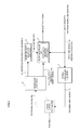
- FIG. 1 shows a principle of an echo processing method and device according to the present invention.
- the above-mentioned first step (or portion) corresponds to a signal converter 2
- the second step (or portion) corresponds to a separator 3
- the third step (or portion) corresponds to an echo section detector 4
- the fourth step (or portion) corresponds to an echo canceller (or echo level measure) 5 .
- a 2-wire/4-wire converter 1 which will be described later is not indispensable for the present invention as shown by a dotted line.
- a signal Fs restricted to a specified frequency band e.g. a high frequency band equal to or more than a predetermined frequency
- a near end signal (reference signal) As is internally generated in conformity with a near end signal (reference signal) As.
- the signal Fs is added to the near end signal As to be outputted as a transmitting signal Ts. Accordingly, a spectrum of the transmitting signal Ts appears as shown in FIG. 2A .
- the transmitting signal Ts not only leaks into a receiving signal Rs through the 2-wire/4-wire converter 1 as mentioned above but also turns around through a path between e.g. a speaker and a microphone on a far end side in some cases, regardless of the existence of the 2-wire/4-wire converter 1 .
- the separator 3 separates the receiving signal Rs into the above-mentioned specified frequency band signal Fs and a signal of a band other than the specified frequency band (non-specified frequency band signal) Ns.
- the specified frequency band signal Fs is transmitted to the echo section detector 4 .
- the echo section detector 4 detects an echo section Ep based on the specified frequency band signal Fs, and generates a signal indicating the echo section Ep to be transmitted to the echo canceller (or echo level measure) 5 .
- an echo component Ec in the non-specified frequency band signal Ns is removed only in the echo section Ep based on the near end signal (reference signal) As, whereby an output signal Os is generated.
- a level of the echo component in the non-specified frequency band signal Ns is detected only in the echo section Ep based on the reference signal As, whereby the output signal Os indicating the level is generated.
- the specified frequency band signal Fs is added to the near end signal As, the specified frequency band signal Fs is received as an echo.
- a far end signal Ds is e.g. a telephone band (equal to or less than 4 kHz) shown in FIG. 2B as a predetermined frequency band, so that only the echo component Ec exists in the specified frequency band signal Fs equal to or more than the telephone band.
- the echo section Ep can be detected with a high accuracy, thereby enabling the removal or the level detection of the echo component to be accurately performed.
- the above-mentioned third step may include a step of (or portion) comparing an amplitude or power of the signal of the specified frequency band with a predetermined threshold, of determining the echo section when the amplitude or power is more than the threshold, and of determining a non-echo section when the amplitude or power is less than the threshold value.
- the above-mentioned first step may include a step of (or portion) determining whether or not voice is included in the near end signal, and a step of (or portion) generating, when it is determined that the voice is included in the near end signal, the signal of the specified frequency band and of adding the generated signal to the near end signal to form the transmitting signal.
- the above-mentioned first step may include a step of (or portion) calculating power of the near end signal, and a step of (or portion) generating the signal of the specified frequency band based on the power of the near end signal and of adding the generated signal to the near end signal to form the transmitting signal.
- the above-mentioned first step may include a step of (or portion) acquiring a spectrum of the near end signal, a step of (or portion) converting the spectrum into a spectrum of the specified frequency band, and a step of (or portion) adding the spectrum of the near end signal with the spectrum of the specified frequency band to be converted into the transmitting signal in time domain.
- the above-mentioned first step may include a step of (or portion) acquiring a pitch frequency of the near end signal, a step of (or portion) generating in the specified frequency band a spectrum having a pitch in a vicinity of frequencies of an integral multiple of the pitch frequency, and a step of (or portion) acquiring a spectrum of the near end signal, of adding the spectrum of the near end signal to the spectrum generated in the specified frequency band to be converted into the transmitting signal in time domain.
- the above-mentioned signal of the specified frequency band may comprise e.g. a sine wave or a narrowband noise.
- the echo processing method and device enable a line echo section which occurs in some form to be accurately detected, and the removal or the level detection of the echo component to be performed without effects of the far end voice, the echo delay, and the reduction of the echo cancellation amount.
- FIG. 1 is a block diagram showing a principle of an arrangement of an echo processing method and device according to the present invention
- FIGS. 2A and 2B are frequency characteristic diagrams showing an operation principle of the present invention shown in FIG. 1 ;
- FIG. 3 is a block diagram showing an arrangement of an embodiment [1] of an echo processing method and device according to the present invention
- FIG. 4 is a block diagram showing an arrangement of an embodiment [2] of an echo processing method and device according to the present invention
- FIG. 6 is a block diagram showing an arrangement of an embodiment [3] of an echo processing method and device according to the present invention.
- FIG. 7 is a frequency characteristic diagram showing an operation principle of the embodiment [3] shown in FIG. 6 ;
- FIG. 8 is a block diagram showing an arrangement of an embodiment [4] of an echo processing method and device according to the present invention.
- FIG. 9 is a frequency characteristic diagram showing an operation principle of the embodiment [4] shown in FIG. 8 ;
- FIG. 10 is a block diagram illustrating a general line echo
- FIG. 11 is a block diagram showing an arrangement of a general echo canceller.
- FIG. 12 is a block diagram showing an arrangement of a general echo detection method.
- the echo processing method and device according to the present invention are applied to an IP private branch exchange, where the IP private branch exchange 10 is arranged between a public network and an IP network. Consequently, the near end signal (reference signal) As is a digital signal obtained after having passed through a decoder 12 from a packet processor 11 connected to the IP network.
- a signal converter 2 which receives the near end signal As is composed of a voice determining portion 2 _ 1 and a sine wave adder 2 _ 2 .
- the digital transmitting signal Ts outputted from the signal converter 2 is converted into an analog signal by a digital/analog converter (DAC) 13 to be transmitted to the 2-wire/4-wire converter 1 .
- DAC digital/analog converter
- the 2-wire/4-wire converter 1 is connected to a public network.
- the far end signal from the public network is converted into the digital receiving signal Rs by an analog/digital converter (ADC) 14 .
- the separator 3 which receives the receiving signal Rs is composed of a lowpass filter (LPF) 3 _ 1 and a highpass filter (HPF) 3 _ 2 .
- the non-specified frequency band signal Ns is outputted from the lowpass filter 3 _ 1
- the specified frequency band signal Fs is outputted from the highpass filter 3 _ 2 .
- the specified frequency band signal Fs is transmitted to an adaptive filter 5 _ 1 forming the echo canceller 5 as the echo section signal Ep through the echo section detector 4 .
- the non-specified frequency band signal Ns is transmitted to a subtractor 5 _ 2 forming the echo canceller 5 as well.
- the adaptive filter 5 _ 1 outputs the estimated echo signal Ec as described in the prior art example shown in FIG. 11 . In this case, the adaptive filter 5 _ 1 is driven only when the echo section signal Ep is generated (level “1”).
- the subtractor 5 _ 2 subtracts the estimated echo signal Ec from the non-specified frequency band signal Ns to output the error signal Es.
- the error signal Es is transmitted from the packet processor 11 to the IP network through an encoder 15 .
- the signal converter 2 , the separator 3 , the echo section detector 4 , and the echo canceller 5 shown in FIGS. 1 and 3 operate with a digital signal.
- the packet processor 11 takes received code data out of a packet received from the IP network.
- the decoder 12 decodes the received code data to generate the near end signal (reference signal) As.
- the voice determining portion 2 _ 1 of the signal converter 2 receives the near end signal As as an input to determine whether or not the near end signal As includes voice.
- the sine wave adder 2 _ 2 When the voice determination result of the voice determining portion 2 _ 1 is “voiced”, the sine wave adder 2 _ 2 generates a sine wave of 6 kHz (specified frequency band signal Fs shown in FIG. 2A ), and adds the near end signal As to the sine wave to form the transmitting signal. When the determination result is “voiceless”, the near end signal As is made a transmitting signal as it is.
- the voice determining portion 2 _ 1 generates the sine wave only in the case of “voiced”
- the sine wave adder 2 _ 2 may be an adder which simply adds the output signal of the voice determining portion 2 _ 1 to the near end signal As.
- the DAC 13 converts the digital transmitting signal Ts into the analog signal to be transmitted to the 2-wire/4-wire converter 1 .
- the ADC 14 converts the analog signal received from the public network through the 2-wire/4-wire converter 1 into the digital signal to generate the receiving signal Rs.
- the HPF 2 _ 2 and the LPF 2 _ 1 separate the receiving signal Rs into the specified frequency band Fs of 6 kHz which is a highpass signal exceeding 4 kHz, and the non-specified frequency band Ns which is a lowpass signal equal to or less than 4 kHz.
- the echo section detector 4 compares the amplitude of the highpass signal Fs with a predetermined threshold, and outputs the determination result as the echo section signal Ep. It is to be noted that when the amplitude is larger than the threshold, the section is determined to be the echo section while when it is less than the threshold, the section is determined to be the non-echo section.
- the adaptive filter 5 _ 1 convolves the filter coefficients with the near end signal As being made a reference signal to generate the pseudo echo signal Ec.
- the subtractor 5 _ 2 subtracts the pseudo echo signal Ec from the lowpass signal Ns to generate the output signal Os.
- the subtractor 5 _ 2 feeds back the output signal Os as the error signal Es to the adaptive filter 5 _ 1 , where the filter coefficients are updated.
- the encoder 15 encodes the output signal Os to generate transmitting code data.
- the packet processor 11 packetizes the transmitting code data to be transmitted to the IP network.
- the echo processing method and device according to the present invention are applied to a voice communication device. Consequently, the voice communication device 20 is only connected to the public network through the 2-wire/4-wire converter 1 .
- the near end signal (reference signal) As is obtained by passing a voice signal from a microphone 21 through an analog/digital converter (ADC) 22 .
- the output signal Os of the echo canceller 5 is outputted from a speaker 24 as a voice signal through a digital/analog converter (DAC) 23 .
- the signal converter 2 is composed of a power calculator 2 _ 3 and a narrowband noise adder 2 _ 4 .
- the voice signal of the microphone 21 becomes the near end signal As digitalized, which has a digital value X[n] (“n” indicates time).
- the narrowband noise adder 2 _ 4 makes X[n] and P[n] inputs to output the transmitting signal Ts of a digital value S[n], which is given by the following equation:
- the DAC 13 converts the transmitting signal S[n] into the analog signal to be transmitted.
- the receiving signal from the 2-wire/4-wire converter 1 becomes the receiving signal Rs of a value R[n] digitalized at the ADC 14 .
- the HPF 2 _ 2 and the LPF 2 _ 1 separate the digital value R[n] into the specified frequency band Fs of a highpass signal H[n] and the non-specified frequency band Ns of a lowpass signal L[n].
- the echo section detector 4 observes the power of the H[n], thereby detecting the echo section Ep as shown by the following equations:
- J[n ] of echo section signal Ep 0 Eq. (3)
- the echo canceller 5 suppresses the echo component included in the lowpass signal from the lowpass signal L[n] and the reference signal X[n] to output the output signal Os of a digital value Y[n].
- a detection result J[n] of the echo section Ep is used.
- the DAC 23 converts the output signal Y[n] into an analog signal to be reproduced from the speaker 24 .
- the echo processing method and device according to the present invention are applied to the voice communication device 20 in the same way as the above-mentioned embodiment [2].
- this embodiment [3] is different from the above-mentioned embodiment [2] in that the signal converter 2 is composed of a spectrum analyzer 2 _ 5 and a specified frequency band signal adder 2 _ 6 .
- the signal converter 2 is composed of a spectrum analyzer 2 _ 5 and a specified frequency band signal adder 2 _ 6 .
- the specified frequency band signal adder 2 _ 6 further obtains a spectrum X′(f) by adding the spectrum X (4000+f) to the spectrum X(f), and converts the spectrum X′(f) into a time domain to be outputted as the transmitting signal Ts.
- the echo processing method and device according to the present invention are applied to the voice communication device 20 in the same way as the above-mentioned embodiments [2] and [3].
- this embodiment [4] is different from the above-mentioned embodiments [2] and [3] in that the signal converter 2 is composed of a pitch analyzer 2 _ 7 and a specified frequency band signal adder 2 _ 8 . Only the operation of the signal converter 2 will now be described.
- the pitch analyzer 2 _ 7 performs a pitch analysis to obtain a pitch frequency f 0 of the near end signal As (see FIG. 9 ).
- the specified frequency band signal adder 2 _ 8 generates a spectrum (see FIG. 9 ) of the specified frequency band of 4-8 kHz based on the following equations:
- A is a preset amplitude (constant)
Abstract
Description
- [Patent Document 1] Japanese Patent Application Laid-open No. 64-27325
- [Patent Document 2] Japanese Patent Application Laid-open No. 63-236423
- [Patent Document 3] Japanese Patent Application Laid-open No. 7-303072
- [Patent Document 4] Japanese Patent Application Laid-open No. 9-312596
(4) The adaptive filter 5_1 convolves the filter coefficients with the near end signal As being made a reference signal to generate the pseudo echo signal Ec. The subtractor 5_2 subtracts the pseudo echo signal Ec from the lowpass signal Ns to generate the output signal Os. Only when the echo section signal Ep is valid “1”, the subtractor 5_2 feeds back the output signal Os as the error signal Es to the adaptive filter 5_1, where the filter coefficients are updated.
(5) The
(6) The
J[n] of echo section signal Ep=1 Eq. (2)
J[n] of echo section signal Ep=0 Eq. (3)
(4) The
(5) The
X(4000+f)=X(f)*0.1(constant) Eq. (4)
(3) The specified frequency band signal adder 2_6 further obtains a spectrum X′(f) by adding the spectrum X (4000+f) to the spectrum X(f), and converts the spectrum X′(f) into a time domain to be outputted as the transmitting signal Ts.
-
- When “f” is an integral multiple of f0,
X′(f)=A Eq. (5)
- When “f” is an integral multiple of f0,
-
- In other cases,
X′(f)=0 Eq. (6)
(3) The specified frequency band signal adder 2_8 further obtains the spectrum X(f) of the near end signal As, obtains a spectrum X″ (f) in which the above-mentioned spectrum X′(f) is added to the spectrum X(f), and converts the spectrum X″ (f) into the transmitting signal Ts in a time domain to be outputted.
- In other cases,
Claims (20)
Applications Claiming Priority (2)
| Application Number | Priority Date | Filing Date | Title |
|---|---|---|---|
| JP2006314571A JP4312227B2 (en) | 2006-11-21 | 2006-11-21 | Echo processing method and apparatus |
| JP2006-314571 | 2006-11-21 |
Publications (2)
| Publication Number | Publication Date |
|---|---|
| US20080118055A1 US20080118055A1 (en) | 2008-05-22 |
| US8208623B2 true US8208623B2 (en) | 2012-06-26 |
Family
ID=39365916
Family Applications (1)
| Application Number | Title | Priority Date | Filing Date |
|---|---|---|---|
| US11/863,536 Expired - Fee Related US8208623B2 (en) | 2006-11-21 | 2007-09-28 | Echo processing method and device |
Country Status (3)
| Country | Link |
|---|---|
| US (1) | US8208623B2 (en) |
| EP (1) | EP1940042B1 (en) |
| JP (1) | JP4312227B2 (en) |
Families Citing this family (4)
| Publication number | Priority date | Publication date | Assignee | Title |
|---|---|---|---|---|
| US8238548B2 (en) * | 2008-02-08 | 2012-08-07 | Cisco Technology, Inc. | Controlling echo during double-talk in a voice conference |
| TWI504181B (en) * | 2010-11-29 | 2015-10-11 | Realtek Semiconductor Corp | Communication system and method for cancelling timing relevance of signal |
| TWI424696B (en) * | 2010-11-29 | 2014-01-21 | Realtek Semiconductor Corp | Communication system and method for cancelling timing relevance of signal |
| US8600037B2 (en) * | 2011-06-03 | 2013-12-03 | Apple Inc. | Audio quality and double talk preservation in echo control for voice communications |
Citations (21)
| Publication number | Priority date | Publication date | Assignee | Title |
|---|---|---|---|---|
| US3183313A (en) * | 1960-12-16 | 1965-05-11 | Bell Telephone Labor Inc | Echo suppressor operable by a pilot tone |
| US4558187A (en) * | 1978-08-29 | 1985-12-10 | Cselt - Centro Studi E Laboratori Telecomunicazioni S.P.A. | Digital echo-cancellation method and circuit arrangement |
| US4628157A (en) | 1984-09-07 | 1986-12-09 | At&T Bell Laboratories | Bidirectional adaptive voice frequency repeater |
| JPS62299120A (en) | 1986-06-18 | 1987-12-26 | Fujitsu Ltd | Double talk detection circuit |
| JPS63236423A (en) | 1987-03-25 | 1988-10-03 | Hitachi Ltd | Initialization type echo canceller |
| JPS6427325A (en) | 1987-07-23 | 1989-01-30 | Fujitsu Ltd | Echo canceller |
| US4969144A (en) | 1989-01-03 | 1990-11-06 | Universal Data Systems, Inc. | Adaptive passband echo canceller |
| JPH03218150A (en) | 1990-01-24 | 1991-09-25 | Nec Corp | Double talk detection circuit |
| JPH07303072A (en) | 1994-05-06 | 1995-11-14 | N T T Idou Tsuushinmou Kk | Method and device for detecting double talk |
| JPH09312596A (en) | 1996-05-20 | 1997-12-02 | Kokusai Electric Co Ltd | Echo canceller |
| US6272106B1 (en) | 1994-05-06 | 2001-08-07 | Nit Mobile Communications Network, Inc. | Method and device for detecting double-talk, and echo canceler |
| JP3218150B2 (en) | 1994-07-15 | 2001-10-15 | ダイセル化学工業株式会社 | Non-colorable polycarbonate resin |
| US20030118177A1 (en) | 2001-12-18 | 2003-06-26 | Ahmet Karakas | Method and system for implementing a reduced complexity dual rate echo canceller |
| US20030152152A1 (en) * | 2002-02-14 | 2003-08-14 | Dunne Bruce E. | Audio enhancement communication techniques |
| WO2004042951A1 (en) | 2002-10-30 | 2004-05-21 | Chaos Telecom, Inc. | A multistage nonlinear echo-canceller for digital communication systems with or without frequency division duplexing |
| US20050068985A1 (en) * | 2003-09-30 | 2005-03-31 | Texas Instruments Incorporated | Two-stage symbol alignment method for ADSL transmission in the presence of TCM-ISDN interferers |
| US20060018457A1 (en) * | 2004-06-25 | 2006-01-26 | Takahiro Unno | Voice activity detectors and methods |
| US7068780B1 (en) | 2000-08-30 | 2006-06-27 | Conexant, Inc. | Hybrid echo canceller |
| US20070004286A1 (en) * | 2005-04-12 | 2007-01-04 | Hobbel Jan C | Cancellation of crosstalk energy in communication loops |
| US20070092074A1 (en) * | 2003-11-04 | 2007-04-26 | Oki Electric Industry Co., Ltd. | Echo canceller |
| US7747002B1 (en) * | 2000-03-15 | 2010-06-29 | Broadcom Corporation | Method and system for stereo echo cancellation for VoIP communication systems |
Family Cites Families (2)
| Publication number | Priority date | Publication date | Assignee | Title |
|---|---|---|---|---|
| GB2376855A (en) * | 2001-06-20 | 2002-12-24 | Sony Uk Ltd | Determining symbol synchronisation in an OFDM receiver in response to one of two impulse response estimates |
| KR100502414B1 (en) * | 2002-11-22 | 2005-07-19 | 삼성전자주식회사 | Echo canceller of adsl system and method for training thereof |
-
2006
- 2006-11-21 JP JP2006314571A patent/JP4312227B2/en not_active Expired - Fee Related
-
2007
- 2007-09-28 US US11/863,536 patent/US8208623B2/en not_active Expired - Fee Related
- 2007-10-04 EP EP07019434A patent/EP1940042B1/en not_active Expired - Fee Related
Patent Citations (21)
| Publication number | Priority date | Publication date | Assignee | Title |
|---|---|---|---|---|
| US3183313A (en) * | 1960-12-16 | 1965-05-11 | Bell Telephone Labor Inc | Echo suppressor operable by a pilot tone |
| US4558187A (en) * | 1978-08-29 | 1985-12-10 | Cselt - Centro Studi E Laboratori Telecomunicazioni S.P.A. | Digital echo-cancellation method and circuit arrangement |
| US4628157A (en) | 1984-09-07 | 1986-12-09 | At&T Bell Laboratories | Bidirectional adaptive voice frequency repeater |
| JPS62299120A (en) | 1986-06-18 | 1987-12-26 | Fujitsu Ltd | Double talk detection circuit |
| JPS63236423A (en) | 1987-03-25 | 1988-10-03 | Hitachi Ltd | Initialization type echo canceller |
| JPS6427325A (en) | 1987-07-23 | 1989-01-30 | Fujitsu Ltd | Echo canceller |
| US4969144A (en) | 1989-01-03 | 1990-11-06 | Universal Data Systems, Inc. | Adaptive passband echo canceller |
| JPH03218150A (en) | 1990-01-24 | 1991-09-25 | Nec Corp | Double talk detection circuit |
| US6272106B1 (en) | 1994-05-06 | 2001-08-07 | Nit Mobile Communications Network, Inc. | Method and device for detecting double-talk, and echo canceler |
| JPH07303072A (en) | 1994-05-06 | 1995-11-14 | N T T Idou Tsuushinmou Kk | Method and device for detecting double talk |
| JP3218150B2 (en) | 1994-07-15 | 2001-10-15 | ダイセル化学工業株式会社 | Non-colorable polycarbonate resin |
| JPH09312596A (en) | 1996-05-20 | 1997-12-02 | Kokusai Electric Co Ltd | Echo canceller |
| US7747002B1 (en) * | 2000-03-15 | 2010-06-29 | Broadcom Corporation | Method and system for stereo echo cancellation for VoIP communication systems |
| US7068780B1 (en) | 2000-08-30 | 2006-06-27 | Conexant, Inc. | Hybrid echo canceller |
| US20030118177A1 (en) | 2001-12-18 | 2003-06-26 | Ahmet Karakas | Method and system for implementing a reduced complexity dual rate echo canceller |
| US20030152152A1 (en) * | 2002-02-14 | 2003-08-14 | Dunne Bruce E. | Audio enhancement communication techniques |
| WO2004042951A1 (en) | 2002-10-30 | 2004-05-21 | Chaos Telecom, Inc. | A multistage nonlinear echo-canceller for digital communication systems with or without frequency division duplexing |
| US20050068985A1 (en) * | 2003-09-30 | 2005-03-31 | Texas Instruments Incorporated | Two-stage symbol alignment method for ADSL transmission in the presence of TCM-ISDN interferers |
| US20070092074A1 (en) * | 2003-11-04 | 2007-04-26 | Oki Electric Industry Co., Ltd. | Echo canceller |
| US20060018457A1 (en) * | 2004-06-25 | 2006-01-26 | Takahiro Unno | Voice activity detectors and methods |
| US20070004286A1 (en) * | 2005-04-12 | 2007-01-04 | Hobbel Jan C | Cancellation of crosstalk energy in communication loops |
Non-Patent Citations (1)
| Title |
|---|
| European Search Report dated May 28, 2008, from the corresponding European Application. |
Also Published As
| Publication number | Publication date |
|---|---|
| US20080118055A1 (en) | 2008-05-22 |
| EP1940042B1 (en) | 2012-11-14 |
| JP4312227B2 (en) | 2009-08-12 |
| JP2008131378A (en) | 2008-06-05 |
| EP1940042A1 (en) | 2008-07-02 |
Similar Documents
| Publication | Publication Date | Title |
|---|---|---|
| JP5036874B2 (en) | Echo canceller | |
| US7856097B2 (en) | Echo canceling apparatus, telephone set using the same, and echo canceling method | |
| US9628141B2 (en) | System and method for acoustic echo cancellation | |
| US7092516B2 (en) | Echo processor generating pseudo background noise with high naturalness | |
| US8644496B2 (en) | Echo suppressor, echo suppressing method, and computer readable storage medium | |
| US8023641B2 (en) | Spectral domain, non-linear echo cancellation method in a hands-free device | |
| US9172817B2 (en) | Communication system | |
| US7558729B1 (en) | Music detection for enhancing echo cancellation and speech coding | |
| US8472616B1 (en) | Self calibration of envelope-based acoustic echo cancellation | |
| US6868158B2 (en) | Echo processing apparatus | |
| US20090238373A1 (en) | System and method for envelope-based acoustic echo cancellation | |
| US20070232257A1 (en) | Noise suppressor | |
| JP2007519316A (en) | Double talk activity detector and method for echo canceller circuit | |
| JP2010206515A (en) | Echo canceller | |
| EP2132734B1 (en) | Method of estimating noise levels in a communication system | |
| US6272106B1 (en) | Method and device for detecting double-talk, and echo canceler | |
| JP3406590B2 (en) | Voice communication apparatus and echo processing processor | |
| US8208623B2 (en) | Echo processing method and device | |
| KR19980086461A (en) | Hand-free phone | |
| EP1078474A2 (en) | Echo cancellation in digital data transmission system | |
| JP2009094802A (en) | Telecommunication apparatus | |
| US8369511B2 (en) | Robust method of echo suppressor | |
| JP4403776B2 (en) | Echo canceller | |
| US7856098B1 (en) | Echo cancellation and control in discrete cosine transform domain | |
| US7711107B1 (en) | Perceptual masking of residual echo |
Legal Events
| Date | Code | Title | Description |
|---|---|---|---|
| AS | Assignment |
Owner name: FUJITSU LIMITED, JAPAN Free format text: ASSIGNMENT OF ASSIGNORS INTEREST;ASSIGNORS:OTANI, TAKESHI;SUZUKI, MASANAO;OTA, YASUJI;REEL/FRAME:019894/0783 Effective date: 20070912 |
|
| STCF | Information on status: patent grant |
Free format text: PATENTED CASE |
|
| FEPP | Fee payment procedure |
Free format text: PAYOR NUMBER ASSIGNED (ORIGINAL EVENT CODE: ASPN); ENTITY STATUS OF PATENT OWNER: LARGE ENTITY |
|
| FPAY | Fee payment |
Year of fee payment: 4 |
|
| FEPP | Fee payment procedure |
Free format text: MAINTENANCE FEE REMINDER MAILED (ORIGINAL EVENT CODE: REM.); ENTITY STATUS OF PATENT OWNER: LARGE ENTITY |
|
| LAPS | Lapse for failure to pay maintenance fees |
Free format text: PATENT EXPIRED FOR FAILURE TO PAY MAINTENANCE FEES (ORIGINAL EVENT CODE: EXP.); ENTITY STATUS OF PATENT OWNER: LARGE ENTITY |
|
| STCH | Information on status: patent discontinuation |
Free format text: PATENT EXPIRED DUE TO NONPAYMENT OF MAINTENANCE FEES UNDER 37 CFR 1.362 |
|
| FP | Lapsed due to failure to pay maintenance fee |
Effective date: 20200626 |