US8200048B2 - Measuring apparatus, venturi and venturi insertion tool - Google Patents
Measuring apparatus, venturi and venturi insertion tool Download PDFInfo
- Publication number
- US8200048B2 US8200048B2 US12/612,214 US61221409A US8200048B2 US 8200048 B2 US8200048 B2 US 8200048B2 US 61221409 A US61221409 A US 61221409A US 8200048 B2 US8200048 B2 US 8200048B2
- Authority
- US
- United States
- Prior art keywords
- pressure
- venturi
- temperature
- double
- flow rate
- Prior art date
- Legal status (The legal status is an assumption and is not a legal conclusion. Google has not performed a legal analysis and makes no representation as to the accuracy of the status listed.)
- Active, expires
Links
- 238000003780 insertion Methods 0.000 title abstract description 4
- 230000037431 insertion Effects 0.000 title abstract description 4
- 238000005259 measurement Methods 0.000 claims abstract description 38
- 230000003287 optical effect Effects 0.000 claims abstract description 37
- 238000004519 manufacturing process Methods 0.000 claims abstract description 20
- 239000003129 oil well Substances 0.000 claims abstract description 15
- 238000000605 extraction Methods 0.000 claims abstract description 5
- 238000010276 construction Methods 0.000 claims abstract description 3
- 238000002347 injection Methods 0.000 claims description 16
- 239000007924 injection Substances 0.000 claims description 16
- 239000013307 optical fiber Substances 0.000 claims description 12
- 238000007789 sealing Methods 0.000 claims description 6
- 239000012530 fluid Substances 0.000 claims description 5
- 230000000694 effects Effects 0.000 claims description 2
- 230000009467 reduction Effects 0.000 claims description 2
- 238000004804 winding Methods 0.000 claims description 2
- 238000011144 upstream manufacturing Methods 0.000 claims 1
- 238000009434 installation Methods 0.000 abstract 1
- 210000000078 claw Anatomy 0.000 description 17
- 230000008859 change Effects 0.000 description 6
- 230000008901 benefit Effects 0.000 description 2
- 238000009530 blood pressure measurement Methods 0.000 description 2
- 238000009529 body temperature measurement Methods 0.000 description 2
- 238000005516 engineering process Methods 0.000 description 2
- 230000002706 hydrostatic effect Effects 0.000 description 2
- 239000000463 material Substances 0.000 description 2
- 238000012360 testing method Methods 0.000 description 2
- 230000001174 ascending effect Effects 0.000 description 1
- 230000005540 biological transmission Effects 0.000 description 1
- 238000004364 calculation method Methods 0.000 description 1
- 238000004891 communication Methods 0.000 description 1
- 238000012937 correction Methods 0.000 description 1
- 238000011161 development Methods 0.000 description 1
- 238000010292 electrical insulation Methods 0.000 description 1
- 230000036039 immunity Effects 0.000 description 1
- 238000000034 method Methods 0.000 description 1
- 238000012986 modification Methods 0.000 description 1
- 230000004048 modification Effects 0.000 description 1
- 238000012797 qualification Methods 0.000 description 1
- 230000009257 reactivity Effects 0.000 description 1
- 230000002787 reinforcement Effects 0.000 description 1
- 239000000126 substance Substances 0.000 description 1
Images


Classifications
-
- E—FIXED CONSTRUCTIONS
- E21—EARTH OR ROCK DRILLING; MINING
- E21B—EARTH OR ROCK DRILLING; OBTAINING OIL, GAS, WATER, SOLUBLE OR MELTABLE MATERIALS OR A SLURRY OF MINERALS FROM WELLS
- E21B47/00—Survey of boreholes or wells
- E21B47/06—Measuring temperature or pressure
-
- E—FIXED CONSTRUCTIONS
- E21—EARTH OR ROCK DRILLING; MINING
- E21B—EARTH OR ROCK DRILLING; OBTAINING OIL, GAS, WATER, SOLUBLE OR MELTABLE MATERIALS OR A SLURRY OF MINERALS FROM WELLS
- E21B31/00—Fishing for or freeing objects in boreholes or wells
- E21B31/12—Grappling tools, e.g. tongs or grabs
- E21B31/20—Grappling tools, e.g. tongs or grabs gripping internally, e.g. fishing spears
-
- E—FIXED CONSTRUCTIONS
- E21—EARTH OR ROCK DRILLING; MINING
- E21B—EARTH OR ROCK DRILLING; OBTAINING OIL, GAS, WATER, SOLUBLE OR MELTABLE MATERIALS OR A SLURRY OF MINERALS FROM WELLS
- E21B47/00—Survey of boreholes or wells
- E21B47/10—Locating fluid leaks, intrusions or movements
- E21B47/113—Locating fluid leaks, intrusions or movements using electrical indications; using light radiations
- E21B47/114—Locating fluid leaks, intrusions or movements using electrical indications; using light radiations using light radiation
-
- E—FIXED CONSTRUCTIONS
- E21—EARTH OR ROCK DRILLING; MINING
- E21B—EARTH OR ROCK DRILLING; OBTAINING OIL, GAS, WATER, SOLUBLE OR MELTABLE MATERIALS OR A SLURRY OF MINERALS FROM WELLS
- E21B47/00—Survey of boreholes or wells
- E21B47/12—Means for transmitting measuring-signals or control signals from the well to the surface, or from the surface to the well, e.g. for logging while drilling
- E21B47/13—Means for transmitting measuring-signals or control signals from the well to the surface, or from the surface to the well, e.g. for logging while drilling by electromagnetic energy, e.g. radio frequency
- E21B47/135—Means for transmitting measuring-signals or control signals from the well to the surface, or from the surface to the well, e.g. for logging while drilling by electromagnetic energy, e.g. radio frequency using light waves, e.g. infrared or ultraviolet waves
-
- G—PHYSICS
- G01—MEASURING; TESTING
- G01K—MEASURING TEMPERATURE; MEASURING QUANTITY OF HEAT; THERMALLY-SENSITIVE ELEMENTS NOT OTHERWISE PROVIDED FOR
- G01K11/00—Measuring temperature based upon physical or chemical changes not covered by groups G01K3/00, G01K5/00, G01K7/00 or G01K9/00
- G01K11/32—Measuring temperature based upon physical or chemical changes not covered by groups G01K3/00, G01K5/00, G01K7/00 or G01K9/00 using changes in transmittance, scattering or luminescence in optical fibres
- G01K11/3206—Measuring temperature based upon physical or chemical changes not covered by groups G01K3/00, G01K5/00, G01K7/00 or G01K9/00 using changes in transmittance, scattering or luminescence in optical fibres at discrete locations in the fibre, e.g. using Bragg scattering
-
- G—PHYSICS
- G01—MEASURING; TESTING
- G01K—MEASURING TEMPERATURE; MEASURING QUANTITY OF HEAT; THERMALLY-SENSITIVE ELEMENTS NOT OTHERWISE PROVIDED FOR
- G01K13/00—Thermometers specially adapted for specific purposes
- G01K13/02—Thermometers specially adapted for specific purposes for measuring temperature of moving fluids or granular materials capable of flow
-
- G—PHYSICS
- G01—MEASURING; TESTING
- G01L—MEASURING FORCE, STRESS, TORQUE, WORK, MECHANICAL POWER, MECHANICAL EFFICIENCY, OR FLUID PRESSURE
- G01L11/00—Measuring steady or quasi-steady pressure of a fluid or a fluent solid material by means not provided for in group G01L7/00 or G01L9/00
- G01L11/02—Measuring steady or quasi-steady pressure of a fluid or a fluent solid material by means not provided for in group G01L7/00 or G01L9/00 by optical means
- G01L11/025—Measuring steady or quasi-steady pressure of a fluid or a fluent solid material by means not provided for in group G01L7/00 or G01L9/00 by optical means using a pressure-sensitive optical fibre
Definitions
- This invention relates to a device which co-ordinates in one single assembly the measurement both of temperature and pressure and of flow rate in oil wells, these measurements being taken in real time by means of optical sensors.
- the device uses an insertable venturi, with which it is possible to measure the flow rate of the well, with the advantage of allowing its replacement whenever a venturi with features different from the one which is being used is necessary.
- the invention applies especially to measurements in oil wells.
- optical fibers as sensors/transmitters for the measurement of the most varied physical and chemical quantities is a technology which is in genuine development.
- optical fibers In view of their features of light weight, flexibility, long transmission distance, low reactivity of the material, electrical insulation, electromagnetic immunity, long working life, in addition to dispensing with electronic circuits and movable mechanical elements at the place of measurement, when combined with the use of Bragg gratings, make the optical fiber extremely advantageous for measurements in places difficult of access. This is a common situation in, for example, the operation of oil production wells.
- transducers were developed for measurement of temperature and pressure, described in Brazilian patent document PI 0403240-3 and transducers were used for the measurement of flow rate, described in Brazilian patent document PI 0403786-3, with the use of optical fiber.
- the invention is capable of measuring pressure and temperature both in the ring and in the tubing of oil wells, as the sensor used is different from the one described in patent PI 0403240-3.
- the sensor used is known as 2P2T (double pressure and temperature).
- 2P2T double pressure and temperature
- This “GS” tool works in conjunction with the known wire line operation.
- This invention consists of equipment for measuring temperature, pressure and flow rate in oil wells. It comprises one single hybrid mandrel to which are fitted a double transducer for measuring pressure and temperature in the tubing and ring, and a pressure differential transducer for measuring the flow rate. In this configuration, there are four pressure points; two for measuring internal pressure in the tubing and external pressure in the ring and two for measuring the internal pressure difference in the tubing (flow rate). In addition, an insertable venturi tube is fitted, which is fastened in a removable manner to the mandrel. In this configuration, it is necessary to carry out one single cable-sensor optical correction in order for the two sensors to be connected in series, which makes the system compact, thus optimizing fitting, making it much faster and more effective.
- the hybrid mandrel of this invention comprises, essentially, an upper body, central body, lower body, central and side covers, an insertable venturi, double pressure and temperature transducer and a differential pressure transducer. With this configuration, several mandrels can be intercalated in the production tubing, making it possible to take measurements at various different levels in the well.
- FIG. 1 shows a side view of the hybrid mandrel of the invention.
- FIG. 2 shows a top view of the hybrid mandrel of the invention.
- FIG. 3 shows a section, as indicated in FIG. 2 .
- FIG. 4 shows an exploded view of the hybrid mandrel.
- FIG. 5 a shows a perspective view of the pack off type of venturi.
- FIG. 5 b shows a side view of the pack off.
- FIG. 5 c shows a section, as indicated in FIG. 5 b.
- FIG. 6 a shows a perspective view of the insertion and extraction tool (GS).
- FIG. 6 b shows an exploded view of the GS tool.
- FIG. 6 c shows a side view of the GS tool fitted.
- FIG. 6 d shows a section, as indicated in FIG. 6 c.
- FIG. 7 a shows a perspective view of the injection venturi.
- FIG. 7 b shows a side view of the injection venturi.
- FIG. 7 c shows a section, as indicated in FIG. 7 b.
- FIG. 8 a shows a perspective view of the production venturi.
- FIG. 8 b shows an exploded view of the production venturi.
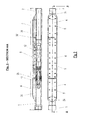
- FIG. 8 c shows a partially sectioned side view of the production venturi.
- FIG. 9 shows a perspective of the central cover, with the lower part turned upwards.
- the equipment for measuring which is the subject of this invention, is fitted in a hybrid mandrel ( 30 ) comprising essentially the following components: upper body ( 1 ), central body ( 2 ), lower body ( 3 ), central cover ( 5 ), side covers ( 4 ), insertable venturi ( 12 ), double pressure and temperature transducer ( 7 ) and differential pressure transducer ( 18 ).
- a hybrid mandrel ( 30 ) comprising essentially the following components: upper body ( 1 ), central body ( 2 ), lower body ( 3 ), central cover ( 5 ), side covers ( 4 ), insertable venturi ( 12 ), double pressure and temperature transducer ( 7 ) and differential pressure transducer ( 18 ).
- the upper body ( 1 ) and lower body ( 3 ) are each fastened to an end of the central body ( 2 ), forming a single part.
- sealing rings ( 8 ) of the O-ring type are used, as shown in greater detail in FIG. 4 .
- the central body ( 2 ) On its upper face, the central body ( 2 ) has two holes ( 19 )—shown in detail in FIG. 4 —which communicate with the inside of the insertable venturi ( 12 )—shown in detail in FIG. 3 and with the differential pressure transducer ( 18 ), in order for it to read the pressure differential and a third hole ( 20 ), which communicates with the inside of the hybrid mandrel ( 30 ) and with the pressure and temperature double transducer ( 7 ), in order for it to read pressure and temperature in the well tubing.
- two holes ( 19 ) shown in detail in FIG. 4 —which communicate with the inside of the insertable venturi ( 12 )—shown in detail in FIG. 3 and with the differential pressure transducer ( 18 ), in order for it to read the pressure differential
- a third hole ( 20 ) which communicates with the inside of the hybrid mandrel ( 30 ) and with the pressure and temperature double transducer ( 7 ), in order for it to read pressure and temperature in the well tubing
- the central body ( 2 ) also has tapped holes ( 21 ) in its upper face for taking the screws ( 6 ) of the central cover ( 5 ) and screws ( 9 ) of the differential pressure transducer ( 18 ) and double pressure and temperature transducer ( 7 ).
- fastened to the central body ( 2 ) are also the guides ( 22 ) for the fitting in of rings (not shown) which guide the passing of the optical fibre (not shown) through the slits ( 24 ) of the side covers ( 4 ) to the hole ( 26 ) in the central cover ( 5 ).
- the double pressure and temperature transducer ( 7 ) and the differential pressure transducer ( 18 ) are fastened to the central body ( 2 ) by means of the fastening screws ( 9 ).
- a ring ( 15 ) of substantially rectangular format is used.
- O-ring type rings ( 10 and 11 ) are placed on all the screws ( 6 ) in the space between the central cover ( 5 ) and the central body ( 2 ).
- the screws ( 6 ) which hold the central cover ( 5 ) can have seal washers ( 14 ).
- sealing rings ( 40 ) it is desirable for sealing rings ( 40 ) to be placed at the holes ( 19 and 20 ) to ensure a perfect seal between the central body ( 2 ) and the two transducers ( 7 and 18 ).
- the main purpose of the lower body ( 3 ) and upper body ( 1 ) is to make possible the connection of the hybrid mandrel ( 30 ) of this invention with the oil production tubing, having for this purpose a male thread on the end of the lower body ( 3 ) and a female thread on the end of the lower [sic] body ( 1 ). They each have a side cover ( 4 ), which is fastened by means of the fastening screws ( 6 ).
- the side covers ( 4 ) have slits ( 24 ) on their lower faces to allow the optical fiber cable to pass to the inside of the hybrid mandrel ( 30 ).
- the central cover ( 5 ) has a recess ( 25 ) along its lower face, which begins close to one end and ends close to the other end. At each end of the central cover, the recess communicates with the outside by means of a hole ( 26 and 26 ′).
- the holes ( 26 and 26 ′) coincide with the slits ( 24 ) of the two side covers ( 4 ), for passing the optical fibre through (see FIG. 3 ).
- the recess ( 25 ) widens, so that they can be fitted in.
- the central cover ( 5 ) also has a hole ( 36 ) (see FIG. 4 ) coinciding with the double pressure and temperature transducer ( 7 ) so that it can read pressure and temperature in the ring where the hybrid mandrel ( 30 ) is inserted.
- a sealing ring ( 39 ) is inserted between the central cover ( 5 ) and the double transducer ( 7 ) so as to isolate interference with the reading taken by the double pressure and temperature transducer ( 7 ) on the outside of the hybrid mandrel ( 30 ). If necessary, the hole ( 36 ) can be closed up with a plug ( 37 ) and an O-ring type of ring ( 38 ).
- the insertable venturi ( 12 ) appears in two types: one for injection ( 12 a ), shown in FIGS. 7 a to 7 c and the other for production ( 12 b ), shown in FIGS. 8 a to 8 c .
- the first one is for being used in operations of injecting fluids into wells and the second one is for being used in oil extraction operations.
- Each of the two types has the same basic construction. Externally, they have a cylindrical section and internally they have a reduction of the straight section, to produce the venturi effect.
- another type of venturi was developed. This is known as pack off ( 29 ) and is shown in FIGS. 5 a to 5 c .
- This pack off is a type of blind venturi, the purpose of which is to protect the optical sensors so that they are not damaged when the oil well production tubing is pressurised in order for the packer to seat.
- the injection insertable venturi ( 12 a ) has several slits along its outside diameter.
- a first slit ( 16 ) communicates with four holes which start from the venturi section of the smallest diameter and—after the fitting of the insertable venturi ( 12 a ) to the hybrid mandrel ( 30 ), it is aligned with one of the two holes ( 19 ).
- Close to this first slit are two other slits ( 31 ), one each side, which are fitted with O-rings to produce a perfect seal against the internal wall of the hybrid mandrel ( 30 ), so as to isolate interference with the reading taken by the differential pressure transducer ( 18 ).
- a fourth slit ( 32 ) which, after the fitting of the insertable venturi ( 12 a ) in the hybrid mandrel ( 30 ), is aligned with the second of the two holes ( 19 ). From this slit, four longitudinal slits ( 33 ) lead off and run to four transverse slits ( 34 ), which communicate with the inside of the insertable venturi ( 12 a ) in its section of greatest diameter.
- one of these transverse slits ( 34 ) is aligned with the hole ( 20 ), making it possible for the double pressure and temperature transducer ( 7 ) to measure temperature and pressure in the inside of the well tubing.
- the alignment of one of the transverse slits ( 34 ) with the hole ( 20 ) near the insertable venturi ( 12 ) only exists so that the pressure point is not obstructed, i.e. so that there is communication of the double transducer ( 7 ) with the well tubing.
- the pressure prevailing at this spot is transmitted through the transverse slit ( 34 ) of the longitudinal slit ( 33 ) and from the fourth slit ( 32 ) to the second of the two holes ( 19 ), making it possible for the differential pressure transducer ( 18 ) to measure the differential pressure between the largest and smallest section of the venturi.
- a fifth slit ( 35 ) which is also fitted with an O-ring. This O-ring and the O-ring to the left of the first slit ( 16 ) produce a second sealed area for preventing interference with the readings of the two transducers ( 7 and 18 ).
- the production insertable venturi ( 12 b ) has the same configuration as the injection insertable venturi ( 12 a ) but with its profile rotated through 180° and having larger dimensions. As it needs to withstand the high upward pressure exerted by the oil being extracted, the insertable venturi ( 12 b ) is fitted with a holder ( 42 ) with locks ( 43 ), the objective of which is to hold it in the hybrid mandrel ( 30 ), preventing the oil being extracted from pushing it.
- the holder ( 42 ) is fitted on to the insertable venturi ( 12 b ) as shown in FIGS. 8 a and 8 b .
- the larger size of the production insertable venturi ( 12 b ) is due to the addition of this holder ( 42 ).
- the injection insertable venturi ( 12 a ) receives downward pressure from the fluid being injected into the well and, for this reason, does not need to have locks, as a subtle difference in diameter at the end of the injection venturi body seats the venturi in the mandrel, preventing the injection insertable venturi ( 12 a ) from being pushed by the fluid.
- the transducer ( 7 ) of the double pressure and double temperature type, called 2P2T makes it possible to measure pressure and temperature both in the ring and in the production tubing in an oil well.
- the reading by this transducer ( 7 ) is carried out with the use of optical reading equipment, also known as a data acquisition system, described in Brazilian patent document PI 0403268-3,
- the reading of the pressure and temperature in the ring and in the tubing is carried out by the optical data acquisition system, described in Brazilian patent PI 0403268-3, which reads the change in wavelength of the Bragg grating of the optical sensors and—through a calibration equation—this change in wavelength is converted to pressure and temperature.
- the transducer ( 18 ) for measuring differential pressure is similar to the one described in Brazilian patent document PI 0403786-3.
- the hybrid mandrel ( 30 ) of this invention works with insertable venturis ( 12 ) which have different beta values (beta means the ratio between the largest and smallest diameter of the venturi), so as to adapt it to the flow rate of the well where it is installed.
- the insertable venturis ( 12 ) which are used in hybrid mandrels can have various different betas which correspond to various different flow rates. From among the various types of insertable venturis ( 12 ), the most common are those of beta 0.21, 0.4, 0.5 and 0.6 (production and injection of each one).
- the principle of operation of flow rate measurement is as follows: the passing of the flow through the venturi generates, by means of the differences in velocities at the internal pressure points, a pressure differential between the largest and smallest diameter of the venturi (betas). This pressure difference is measured in the optical pressure differential transducer which converts the pressure difference to a change in wavelength. The surface reading system measures this change and—in accordance with the calibration constants of this sensor—converts the change in optical wavelength to a pressure differential measurement. On the basis of the pressure differential measurement, a calculation is made of the flow rate as such by means of the venturi equations.
- the flow rate measurement can be via the ascending flow or descending flow, i,e. depending on the direction of flow, the sensor can measure in both directions.
- the insertable venturis ( 12 ) of the hybrid mandrel ( 30 ) are made for several types of betas (mathematical ratio between the smallest and largest diameter of the venturi).
- a special tool was developed for inserting and extracting insertable venturis ( 12 ), the said tool being called a GS tool ( 17 ), which is shown in FIGS. 6 a to 6 d and is used in conjunction with the known wire line operation.
- This GS tool ( 17 ) descends, is seated, places and removes any type of insertable venturi ( 12 ), including the blind pack off venturi ( 29 ), in the lowered position.
- claws ( 44 ) On its tip and these are designed to be seated and to lock in the internal fishing neck ( 55 )—shown in detail in FIG. 7 c —of the insertable venturi ( 12 ).
- the GS tool ( 17 ) is used simply by introducing the claws ( 44 ) and core ( 45 ) into the internal fishing neck ( 55 ) of the insertable venturi ( 12 ).
- the claws ( 44 ) withdraw, compressing the spring ( 46 ) of the claw on meeting the chamfered upper part of the insertable venturi ( 12 ) and become concealed in the core ( 45 ).
- the insertable venturi ( 12 ) When the insertable venturi ( 12 ) is duly positioned in its fastening place, downward blows are given, breaking the shear pin ( 47 ) and the core ( 45 ) moves downwards, concealing the claws ( 44 ) with the expansion of the spring ( 46 ) which keeps the core in the lower position.
- a new shear pin ( 47 ) In order for the insertable venturi ( 12 ) to be removed, a new shear pin ( 47 ) must be fitted and the GS tool ( 17 ) must be lowered.
- the GS tool ( 17 ) encounters the restriction of the insertable venturi ( 12 ), successive knocks or blows downwards are given until the insertable venturi ( 12 ) fastens to the GS tool ( 17 ).
- the GS tool ( 17 ) fits into the insertable venturi ( 12 ), the latter is pulled upwards and withdrawn. Due to these features, the GS tool ( 17 ) can be used in external fishing operations.
- the GS tool ( 17 ) also comprises the fishing neck ( 48 ), fastening screw ( 49 ), upper sub ( 50 ), cylinder spring ( 51 ), spring retainer ( 52 ), claw retainer ( 53 ) and cylinder ( 54 ).
- the fishing neck ( 48 ) is designed so that, if the GS tool ( 17 ) comes off the wire line, it is possible to recover it by means of external fishing.
- the fastening screw ( 49 ) serves to prevent the unscrewing of the fishing neck ( 48 ) from the core ( 45 ), i.e. so that the fishing neck ( 48 ) does not become unfastened from the core ( 45 ).
- the upper sub ( 50 ) is the upper part which moves from the GS tool ( 17 ).
- the cylinder spring ( 51 ) is used to move all the movable part of the GS tool ( 17 ).
- the spring retainer ( 52 ) is a part of the GS tool ( 17 ) which keeps the spring compressed beside the shear pin ( 47 ).
- the claw retainer ( 53 ) is used to keep the claws ( 44 ) correctly positioned and equidistant.
- the cylinder ( 54 ) is the external part of the GS tool ( 17 ) which moves all the movable parts of the GS tool ( 17 ).
- the equipment for measurement of double temperature and pressure and flow rate in oil wells was subjected to the qualification tests carried out in a thermal-hyperbaric chamber, which reproduces the conditions of an oil well under thermal and internal and external hydrostatic pressure loads.
- the term internal pressure is used with reference to a pressure applied inside the hybrid mandrel (tubing), whereas the term external pressure refers to a pressure applied inside the thermo-hyperbaric chamber but external to the hybrid mandrel (ring).
- the internal pressure was applied in the value of 7,500 psi for 10 minutes at room temperature, recording the temperature and pressure measurements of the reference transducers of the chamber. Afterwards, the pressure was set to zero and the temperature raised (up) to 90° C.
- 7,500 psi was applied for 10 minutes and the pressure was rapidly set to zero. As the hybrid mandrel did not have any leaks or loss of pressure, it was considered approved.
- the external pressure was applied in the value of 7,500 psi for 10 minutes at room temperature, recording the temperature and pressure measurements of the reference transducers of the chamber. Afterwards, the pressure was set to zero and the temperature raised (up) to 90° C. Then, 7,500 psi was applied for 10 minutes and the pressure was rapidly set to zero. As the hybrid mandrel did not have any leaks or loss of pressure, it was considered approved.
- the equipment for optical measurement and pressure and of flow rate has just been described with reference to the examples and attached drawings as the preferred embodiment of the invention, it shall be understood that various modifications can be introduced without leaving the scope of its protection, it being possible for some elements to be replaced with others with the same technical function, especially the materials used, their dimensions, shapes and proportions.
- the claimed invention is characterized as equipment for optical measurement for double temperature and pressure and of flow rate, the invention may be embodied in the respective handling tool, for use with the equipment for measurement of double temperature and pressure and flow rate, wherein it lowers, seats and places the insertable venturi ( 12 ) in and withdraws it from a hybrid mandrel ( 30 ).
- the handling tool comprises a fishing neck ( 48 ), fastening screw ( 49 ), upper sub ( 50 ), cylinder spring ( 51 ), spring retainer ( 52 ), claw spring ( 46 ), claw retainer ( 53 ), shear pin ( 47 ), core ( 45 ), claws ( 44 ) and cylinder ( 54 ), in which: the claws ( 44 ) are designed to be seated and to lock in the internal fishing neck ( 55 ) of the insertable venturi ( 12 ), which withdraw, compressing the claw spring ( 46 ) on meeting the chamfered upper part of the insertable venturi ( 12 ), becoming concealed in the core ( 45 ) and, on reaching the restriction and due to the expansion of the spring ( 46 ), fasten together in the restriction of the internal fishing neck ( 55 ) of the insertable venturi ( 12 ), the shear pin ( 47 ) is breakable and, when this happens, the core ( 45 ) moves downwards, concealing the claws ( 44 ) with the expansion of the spring ( 46 ) which keeps the core in
Landscapes
- Physics & Mathematics (AREA)
- Engineering & Computer Science (AREA)
- Life Sciences & Earth Sciences (AREA)
- Mining & Mineral Resources (AREA)
- Geology (AREA)
- Geochemistry & Mineralogy (AREA)
- General Life Sciences & Earth Sciences (AREA)
- Environmental & Geological Engineering (AREA)
- Fluid Mechanics (AREA)
- Geophysics (AREA)
- Remote Sensing (AREA)
- General Physics & Mathematics (AREA)
- Electromagnetism (AREA)
- Marine Sciences & Fisheries (AREA)
- Health & Medical Sciences (AREA)
- Toxicology (AREA)
- Measuring Fluid Pressure (AREA)
- Measuring Volume Flow (AREA)
Abstract
Description
Claims (15)
Applications Claiming Priority (3)
| Application Number | Priority Date | Filing Date | Title |
|---|---|---|---|
| BRPI0804823-1 | 2008-11-05 | ||
| BRPI0804823A BRPI0804823B1 (en) | 2008-11-05 | 2008-11-05 | dual temperature and pressure and flow optical measurement equipment |
| BR0804823 | 2008-11-05 |
Publications (2)
| Publication Number | Publication Date |
|---|---|
| US20100111467A1 US20100111467A1 (en) | 2010-05-06 |
| US8200048B2 true US8200048B2 (en) | 2012-06-12 |
Family
ID=41690043
Family Applications (1)
| Application Number | Title | Priority Date | Filing Date |
|---|---|---|---|
| US12/612,214 Active 2030-09-14 US8200048B2 (en) | 2008-11-05 | 2009-11-04 | Measuring apparatus, venturi and venturi insertion tool |
Country Status (5)
| Country | Link |
|---|---|
| US (1) | US8200048B2 (en) |
| EP (1) | EP2184438B1 (en) |
| AR (1) | AR073994A1 (en) |
| BR (1) | BRPI0804823B1 (en) |
| CO (1) | CO6320149A1 (en) |
Cited By (2)
| Publication number | Priority date | Publication date | Assignee | Title |
|---|---|---|---|---|
| US20170314389A1 (en) * | 2016-04-29 | 2017-11-02 | Baker Hughes Incorporated | Method for packaging components, assemblies and modules in downhole tools |
| US11209024B2 (en) | 2015-06-24 | 2021-12-28 | Itt Manufacturing Enterprises Llc | Discharge casing insert for pump performance characteristics control |
Families Citing this family (4)
| Publication number | Priority date | Publication date | Assignee | Title |
|---|---|---|---|---|
| AU2012364830B2 (en) | 2012-01-12 | 2014-10-02 | Micro Motion, Inc. | Meter having banded shroud |
| US10120102B2 (en) | 2015-11-04 | 2018-11-06 | General Electric Company | Fluid sensor cable assembly, system, and method |
| CN109611081B (en) * | 2018-12-29 | 2021-08-24 | 中国科学院地质与地球物理研究所 | Instrument while drilling fluid pressure measuring device |
| CN110161281B (en) * | 2019-06-14 | 2022-03-04 | 山东省科学院激光研究所 | A fiber optic flow sensor |
Citations (4)
| Publication number | Priority date | Publication date | Assignee | Title |
|---|---|---|---|---|
| US6082455A (en) * | 1998-07-08 | 2000-07-04 | Camco International Inc. | Combination side pocket mandrel flow measurement and control assembly |
| US6915686B2 (en) * | 2003-02-11 | 2005-07-12 | Optoplan A.S. | Downhole sub for instrumentation |
| US7266261B2 (en) | 2004-09-09 | 2007-09-04 | Petroleo Brasileiro S.A.-Petrobras | Fiber optics differential pressure transducer |
| US7308165B2 (en) | 2004-08-10 | 2007-12-11 | Petroleo Brasileiro S.A. - Petrobras | Optical transducer and method for the simultaneous measurement of pressure and temperature in oil and gas wells |
Family Cites Families (10)
| Publication number | Priority date | Publication date | Assignee | Title |
|---|---|---|---|---|
| US4838594A (en) * | 1986-10-06 | 1989-06-13 | Otis Engineering Corporation | Running and pulling tool |
| DE19860409A1 (en) * | 1998-12-28 | 2000-06-29 | Abb Research Ltd | Fiber Bragg grating sensor for measuring differential pressures and flow velocities |
| US6785004B2 (en) * | 2000-11-29 | 2004-08-31 | Weatherford/Lamb, Inc. | Method and apparatus for interrogating fiber optic sensors |
| US6782150B2 (en) * | 2000-11-29 | 2004-08-24 | Weatherford/Lamb, Inc. | Apparatus for sensing fluid in a pipe |
| US6698297B2 (en) * | 2002-06-28 | 2004-03-02 | Weatherford/Lamb, Inc. | Venturi augmented flow meter |
| US6986276B2 (en) * | 2003-03-07 | 2006-01-17 | Weatherford/Lamb, Inc. | Deployable mandrel for downhole measurements |
| MY140093A (en) * | 2003-11-07 | 2009-11-30 | Peak Well Systems Pty Ltd | A retrievable downhole tool and running tool |
| US7159468B2 (en) * | 2004-06-15 | 2007-01-09 | Halliburton Energy Services, Inc. | Fiber optic differential pressure sensor |
| BRPI0403268B1 (en) | 2004-08-10 | 2017-07-18 | Petroleo Brasileiro S.A. - Petrobras | SYSTEM FOR READING AND DATA ACQUISITION FOR FIBER OPTICAL SENSORS |
| WO2007003445A1 (en) * | 2005-02-03 | 2007-01-11 | Philip Head | Sensor system for gas lift wells |
-
2008
- 2008-11-05 BR BRPI0804823A patent/BRPI0804823B1/en active IP Right Grant
-
2009
- 2009-10-27 AR ARP090104138A patent/AR073994A1/en active IP Right Grant
- 2009-11-04 US US12/612,214 patent/US8200048B2/en active Active
- 2009-11-05 CO CO09125395A patent/CO6320149A1/en active IP Right Grant
- 2009-11-05 EP EP09252556.7A patent/EP2184438B1/en active Active
Patent Citations (4)
| Publication number | Priority date | Publication date | Assignee | Title |
|---|---|---|---|---|
| US6082455A (en) * | 1998-07-08 | 2000-07-04 | Camco International Inc. | Combination side pocket mandrel flow measurement and control assembly |
| US6915686B2 (en) * | 2003-02-11 | 2005-07-12 | Optoplan A.S. | Downhole sub for instrumentation |
| US7308165B2 (en) | 2004-08-10 | 2007-12-11 | Petroleo Brasileiro S.A. - Petrobras | Optical transducer and method for the simultaneous measurement of pressure and temperature in oil and gas wells |
| US7266261B2 (en) | 2004-09-09 | 2007-09-04 | Petroleo Brasileiro S.A.-Petrobras | Fiber optics differential pressure transducer |
Cited By (3)
| Publication number | Priority date | Publication date | Assignee | Title |
|---|---|---|---|---|
| US11209024B2 (en) | 2015-06-24 | 2021-12-28 | Itt Manufacturing Enterprises Llc | Discharge casing insert for pump performance characteristics control |
| US20170314389A1 (en) * | 2016-04-29 | 2017-11-02 | Baker Hughes Incorporated | Method for packaging components, assemblies and modules in downhole tools |
| US12571265B2 (en) | 2016-04-29 | 2026-03-10 | Baker Hughes Holdings Llc | Method for packaging components, assemblies and modules in downhole tools |
Also Published As
| Publication number | Publication date |
|---|---|
| CO6320149A1 (en) | 2011-09-20 |
| BRPI0804823B1 (en) | 2018-09-11 |
| EP2184438A3 (en) | 2016-06-08 |
| EP2184438B1 (en) | 2018-12-26 |
| AR073994A1 (en) | 2010-12-15 |
| BRPI0804823A2 (en) | 2010-07-27 |
| EP2184438A2 (en) | 2010-05-12 |
| US20100111467A1 (en) | 2010-05-06 |
Similar Documents
| Publication | Publication Date | Title |
|---|---|---|
| US8200048B2 (en) | Measuring apparatus, venturi and venturi insertion tool | |
| US10648325B2 (en) | Wireless downhole feedthrough system | |
| US7658117B2 (en) | Flow meter using an expanded tube section and sensitive differential pressure measurement | |
| EP2401475B1 (en) | System and method for wellbore monitoring | |
| US5925879A (en) | Oil and gas well packer having fiber optic Bragg Grating sensors for downhole insitu inflation monitoring | |
| US6513596B2 (en) | Non-intrusive pressure measurement device for subsea well casing annuli | |
| US7228912B2 (en) | Method and system to deploy control lines | |
| US9127546B2 (en) | Downhole fluid separation | |
| US20040086623A1 (en) | Storage stable pan release coating and cleaner | |
| NO20120819A1 (en) | Apparatus and method for separating distributed optical fiber pressure sensing in wellbores | |
| US20150323700A1 (en) | In-Situ System Calibration | |
| WO2010086588A2 (en) | Sensing inside and outside tubing | |
| US20130327138A1 (en) | Systems and Methods for Distributed Downhole Sensing Using a Polymeric Sensor System | |
| US11668153B2 (en) | Cement head and fiber sheath for top plug fiber deployment | |
| GB2403292A (en) | System and method for making fiber optic measurements in a wellbore using a downhole opto-electronic uint | |
| WO2004070167A1 (en) | Method and system for the use of a distributed temperature system in a subsea well | |
| WO2013137742A1 (en) | Method and device for determining pressure in a cavity | |
| US4018088A (en) | Borehole pressure measurement apparatus having a high pressure float valve | |
| US9322727B2 (en) | Tension meter for measuring a mechanical tension along a longitudinal direction in a well and related subassembly and method |
Legal Events
| Date | Code | Title | Description |
|---|---|---|---|
| AS | Assignment |
Owner name: PETROLEO BRASILEIRO S.A. - PETROBRAS,BRAZIL Free format text: ASSIGNMENT OF ASSIGNORS INTEREST;ASSIGNORS:VIDAL, JOSE LUIZ ARIAS;BORN, RENATA MERCANTE;LORENZO, JOAO LUIZ DOS SANTOS;AND OTHERS;REEL/FRAME:023468/0839 Effective date: 20090926 Owner name: SURCO TECNOLOGIA INDUSTRIAL LTDA,BRAZIL Free format text: ASSIGNMENT OF ASSIGNORS INTEREST;ASSIGNORS:VIDAL, JOSE LUIZ ARIAS;BORN, RENATA MERCANTE;LORENZO, JOAO LUIZ DOS SANTOS;AND OTHERS;REEL/FRAME:023468/0839 Effective date: 20090926 Owner name: SURCO TECNOLOGIA INDUSTRIAL LTDA, BRAZIL Free format text: ASSIGNMENT OF ASSIGNORS INTEREST;ASSIGNORS:VIDAL, JOSE LUIZ ARIAS;BORN, RENATA MERCANTE;LORENZO, JOAO LUIZ DOS SANTOS;AND OTHERS;REEL/FRAME:023468/0839 Effective date: 20090926 Owner name: PETROLEO BRASILEIRO S.A. - PETROBRAS, BRAZIL Free format text: ASSIGNMENT OF ASSIGNORS INTEREST;ASSIGNORS:VIDAL, JOSE LUIZ ARIAS;BORN, RENATA MERCANTE;LORENZO, JOAO LUIZ DOS SANTOS;AND OTHERS;REEL/FRAME:023468/0839 Effective date: 20090926 |
|
| STCF | Information on status: patent grant |
Free format text: PATENTED CASE |
|
| FPAY | Fee payment |
Year of fee payment: 4 |
|
| MAFP | Maintenance fee payment |
Free format text: PAYMENT OF MAINTENANCE FEE, 8TH YEAR, LARGE ENTITY (ORIGINAL EVENT CODE: M1552); ENTITY STATUS OF PATENT OWNER: LARGE ENTITY Year of fee payment: 8 |
|
| MAFP | Maintenance fee payment |
Free format text: PAYMENT OF MAINTENANCE FEE, 12TH YEAR, LARGE ENTITY (ORIGINAL EVENT CODE: M1553); ENTITY STATUS OF PATENT OWNER: LARGE ENTITY Year of fee payment: 12 |