US8167409B2 - Liquid ejecting head unit and liquid ejecting apparatus - Google Patents
Liquid ejecting head unit and liquid ejecting apparatus Download PDFInfo
- Publication number
- US8167409B2 US8167409B2 US12/726,163 US72616310A US8167409B2 US 8167409 B2 US8167409 B2 US 8167409B2 US 72616310 A US72616310 A US 72616310A US 8167409 B2 US8167409 B2 US 8167409B2
- Authority
- US
- United States
- Prior art keywords
- liquid ejecting
- connector
- ejecting head
- head unit
- wiring
- Prior art date
- Legal status (The legal status is an assumption and is not a legal conclusion. Google has not performed a legal analysis and makes no representation as to the accuracy of the status listed.)
- Expired - Fee Related, expires
Links
- 239000007788 liquid Substances 0.000 title claims abstract description 65
- 230000000717 retained effect Effects 0.000 claims abstract description 5
- 238000007789 sealing Methods 0.000 claims description 13
- 230000001681 protective effect Effects 0.000 description 13
- 239000000758 substrate Substances 0.000 description 9
- 238000003491 array Methods 0.000 description 5
- 230000002708 enhancing effect Effects 0.000 description 3
- 238000000034 method Methods 0.000 description 3
- 230000005855 radiation Effects 0.000 description 3
- 238000007667 floating Methods 0.000 description 2
- 238000007639 printing Methods 0.000 description 2
- 239000011347 resin Substances 0.000 description 2
- 229920005989 resin Polymers 0.000 description 2
- 229920002379 silicone rubber Polymers 0.000 description 2
- 239000004945 silicone rubber Substances 0.000 description 2
- 238000005452 bending Methods 0.000 description 1
- 239000003990 capacitor Substances 0.000 description 1
- 230000002950 deficient Effects 0.000 description 1
- 238000009434 installation Methods 0.000 description 1
- 238000000465 moulding Methods 0.000 description 1
- 230000000007 visual effect Effects 0.000 description 1
Images


Classifications
-
- B—PERFORMING OPERATIONS; TRANSPORTING
- B41—PRINTING; LINING MACHINES; TYPEWRITERS; STAMPS
- B41J—TYPEWRITERS; SELECTIVE PRINTING MECHANISMS, i.e. MECHANISMS PRINTING OTHERWISE THAN FROM A FORME; CORRECTION OF TYPOGRAPHICAL ERRORS
- B41J2/00—Typewriters or selective printing mechanisms characterised by the printing or marking process for which they are designed
- B41J2/005—Typewriters or selective printing mechanisms characterised by the printing or marking process for which they are designed characterised by bringing liquid or particles selectively into contact with a printing material
- B41J2/01—Ink jet
- B41J2/135—Nozzles
- B41J2/145—Arrangement thereof
- B41J2/155—Arrangement thereof for line printing
-
- B—PERFORMING OPERATIONS; TRANSPORTING
- B41—PRINTING; LINING MACHINES; TYPEWRITERS; STAMPS
- B41J—TYPEWRITERS; SELECTIVE PRINTING MECHANISMS, i.e. MECHANISMS PRINTING OTHERWISE THAN FROM A FORME; CORRECTION OF TYPOGRAPHICAL ERRORS
- B41J2202/00—Embodiments of or processes related to ink-jet or thermal heads
- B41J2202/01—Embodiments of or processes related to ink-jet heads
- B41J2202/08—Embodiments of or processes related to ink-jet heads dealing with thermal variations, e.g. cooling
-
- B—PERFORMING OPERATIONS; TRANSPORTING
- B41—PRINTING; LINING MACHINES; TYPEWRITERS; STAMPS
- B41J—TYPEWRITERS; SELECTIVE PRINTING MECHANISMS, i.e. MECHANISMS PRINTING OTHERWISE THAN FROM A FORME; CORRECTION OF TYPOGRAPHICAL ERRORS
- B41J2202/00—Embodiments of or processes related to ink-jet or thermal heads
- B41J2202/01—Embodiments of or processes related to ink-jet heads
- B41J2202/14—Mounting head into the printer
-
- B—PERFORMING OPERATIONS; TRANSPORTING
- B41—PRINTING; LINING MACHINES; TYPEWRITERS; STAMPS
- B41J—TYPEWRITERS; SELECTIVE PRINTING MECHANISMS, i.e. MECHANISMS PRINTING OTHERWISE THAN FROM A FORME; CORRECTION OF TYPOGRAPHICAL ERRORS
- B41J2202/00—Embodiments of or processes related to ink-jet or thermal heads
- B41J2202/01—Embodiments of or processes related to ink-jet heads
- B41J2202/19—Assembling head units
-
- B—PERFORMING OPERATIONS; TRANSPORTING
- B41—PRINTING; LINING MACHINES; TYPEWRITERS; STAMPS
- B41J—TYPEWRITERS; SELECTIVE PRINTING MECHANISMS, i.e. MECHANISMS PRINTING OTHERWISE THAN FROM A FORME; CORRECTION OF TYPOGRAPHICAL ERRORS
- B41J2202/00—Embodiments of or processes related to ink-jet or thermal heads
- B41J2202/01—Embodiments of or processes related to ink-jet heads
- B41J2202/20—Modules
Definitions
- the present invention relates to a liquid ejecting head unit and a liquid ejecting apparatus.
- An existing liquid ejecting apparatus typified by an ink jet recording apparatus such as an ink jet printer includes a liquid ejecting head unit having a plurality of liquid ejecting heads capable of ejecting liquid such as ink stored in a cartridge, tank or the like in the form of droplets.
- a liquid ejecting head unit having a plurality of liquid ejecting heads capable of ejecting liquid such as ink stored in a cartridge, tank or the like in the form of droplets.
- a unit in which a plurality of liquid ejecting heads are fixed on a common retaining member or a base plate in alignment in one direction and in a state of being slightly staggered in the other direction is known as such a liquid ejecting head unit (refer to JP-A-2000-25207 as an example).
- An advantage of some aspects of the invention is that it solves the above-mentioned technical problems of the related art and provides a liquid ejecting head unit with high general versatility in which a head can be relatively easily replaced by the user and which does not cause inferior contact during the replacement procedure, and a liquid ejecting apparatus employing the liquid ejecting head unit.
- An aspect according to the invention provides a liquid ejecting head unit including liquid ejecting head bodies for ejecting liquid by driving a pressure generating device, wiring members for feeding drive signals to the pressure generating device of the liquid ejecting head bodies, and a connector member provided at an end of the wiring members, being connected by the wiring members, and having second connector sections detachable from first connectors of the liquid ejecting head bodies.
- Each of the connector member includes a base member equipped at the connecting section with the wiring member having a wiring member connector for inserting the connecting end of the wiring member for connection, and a retaining member fixed to the base member covering the wiring member connector section. The wiring member inserted into the wiring member connector is retained in a folded state by the retaining member.
- attachment and detachment of the wiring member from the liquid ejecting head body become easier by using the connector member, and the user may relatively readily replace the head. Since the wiring member inserted into the wiring member connector of the connector member is retained between the retaining member and the base member in the folded state, no inferior contact is caused as a result of the replacement procedure.
- the wiring member be pinched between the base member and the retaining member with the connecting end section of the wiring member folded back on itself.
- disconnection of the wiring member from the wiring member connector may be prevented more reliably, since the wiring member is pinched between the base member and the retaining member with the connecting end section of the wiring member folded back on itself.
- said retaining member be detachably fixed to the base member.
- the wiring member may be disconnected when required by detaching the retaining member.
- a first sealing member for sealing the connecting section with the wiring member be provided on at least one of the abutment surfaces between the base member and the retaining member.
- the connecting section of the wiring member is sealed in the space between the base member and the protecting member, thus preventing mist-like liquid from entering the space.
- the retaining member be made from a transparent member.
- the connecting section of the wiring member may readily be checked visually, thus preventing inferior connection or the like in advance.
- a second sealing member for sealing the connecting section between the first connector section and the second connector section be provided on at least one of the abutment surfaces around the first connector section of the liquid ejecting head body or around the second connector section of the base member.
- the connecting section between the first connector section and the second connector section is sealed by the second sealing member, thus preventing mist-like liquid from entering.
- a plurality of first connector sections be provided on the liquid ejecting head body, a plurality of wiring members be connected to the base member, and a plurality of the second connector sections be provided on the base member.
- connection of a plurality of wiring members may be accomplished by using a single connector member.
- Another aspect of the present invention is a liquid ejecting apparatus equipped with the above-mentioned liquid ejecting head unit.
- attachment and detachment of the wiring members from the liquid ejecting head body become easier by using the connector member, and the liquid ejecting apparatus for which the user may relatively readily replace the head may be attained. Since the wiring members inserted into the wiring member connector of the connector member are retained between the retaining member and the base member in the folded state, no inferior contact is caused during the replacement procedure.
- FIGS. 1A and 1B are a perspective view of the head according to an embodiment of the invention and a bottom view of the major sections.
- FIGS. 2A and 2B are exploded perspective views of the connector member according to an embodiment of the invention.
- FIG. 3 is an exploded perspective view of the connector member according to an embodiment of the invention.
- FIG. 4 is a cross-sectional view of the connector member according to an embodiment of the invention.
- FIG. 5 is a perspective view of the base member of the connector member according to an embodiment of the invention.
- FIG. 6 is a perspective view of the head unit according to an embodiment of the present invention.
- FIG. 7 is a top view of the head unit excluding the frame and the signal feed unit.
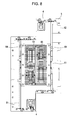
- FIG. 8 is a top view of the head unit according to an embodiment of the invention.
- FIG. 9 is a top view of the head unit excluding the radiation member.
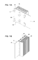
- FIG. 10 is a partially exploded perspective view of the signal feed unit according to an embodiment of the invention.
- FIGS. 11A and 11B are perspective views of the major sections of the signal feed unit according to an embodiment of the invention.
- FIG. 12 is a perspective view of the head unit according to an embodiment of the invention.
- FIG. 1 is used to explain the structure of the head.
- FIG. 1A is a perspective view of the head
- FIG. 1B is a bottom view of the major sections of the head.
- all the members constituting the head unit 1 including the heads 2 ( 2 a through 2 d ) fixed to the base plate 3 , ink feed tubes 4 (liquid feed tube) for feeding ink to the heads 2 , a frame 5 placed upright on the base plate 3 , and a signal feed unit 6 mounted on the base plate 3 are structured and disposed so that they are all accommodated within a columnar space with the base plate 3 serving as the bottom surface. The details are described below.
- the head unit 1 Due to the fact that the members constituting the head unit 1 are housed within the columnar space with the base plate 3 as the bottom surface as mentioned above, the head unit 1 according to this embodiment may be combined with another head unit 1 without allowing the constituting members to come into contact with each other, thus enhancing the general versatility of the unit.
- Each of the heads 2 is paired with another of the heads 2 disposed in juxtaposition of the first direction, and the pair is disposed on the base plate 3 so that each pair forms a substantially staggered array pattern and that the end of a nozzle array 26 of respective heads 2 (see FIG. 1 ) overlaps with the end of another nozzle array 26 of another pair of the heads 2 also placed in the first direction.
- the nozzle arrays 26 are not interrupted in the second direction by pairs of the heads 2 being disposed in substantially staggered array pattern and the ends of the nozzle arrays being overlapped, and the heads 2 can make print for extensive areas at high speed.
- the pitch of the nozzle array of a pair of the heads 2 is staggered by half a pitch, and the resolution may thus be enhanced.
- FIG. 7 is a top view of the head unit excluding the frame and the signal feed unit. Two ink feed tubes 4 are provided in this embodiment.
- Each of the ink feed tubes 4 includes a main channel 41 , individual channels 42 a through 42 d , and head-side individual channels 43 a through 43 d .
- the main channel 41 is connected to an ink reservoir, not shown, at its end.
- the individual channels 42 a through 42 d branched from the main channel 41 are connected to the head-side individual channels 43 a through 43 d via joints 44 at their respective ends.
- the head-side individual channels 43 a through 43 d are branched into two to be connected to the respective ink intake ports 22 of a single head 2 .
- the respective ink feed tubes 4 are structured and disposed to be accommodated within the columnar space with the base plate 3 serving as the bottom surface as shown in FIG. 7 .
- the main channel 41 is branched into two individual channels 42 a and 42 b at a first bifurcation 45 .
- the individual channel 42 a is a branched flow path extending downward after the bifurcation and is connected to the head-side individual channel 43 a connected to the head 2 a .
- the head-side individual channel 43 a is connected to the two ink intake ports 22 provided on the head 2 a .
- the individual channel 42 b extends in the horizontal direction after the bifurcation and is connected to the head-side individual channel 43 b on the head 2 b disposed along the first direction of the head 2 a . From the individual channel 42 b , an individual channel 42 c further extends from a bifurcation 46 .
- the individual channel 42 c extends along the first direction after the bifurcation and is connected to the head-side individual channel 43 c on the head 2 c disposed in juxtaposition of the first direction of the head 2 a .
- an individual channel 42 d further extends from a bifurcation 47 and is connected to the head-side individual channel 43 d on the head 2 d disposed in juxtaposition of the second direction of the head 2 c .
- the other ink feed tube 4 is structured in a similar manner and configured to feed ink to four heads 2 .
- the frame 5 is provided on the base plate 3 , and the signal feed unit 6 for feeding signals for driving the respective heads is mounted on the frame 5 .
- the frame 5 includes four legs 51 and a table 52 supported by the legs 51 . Since the legs 51 are disposed in the vicinity of the head 2 , or along the second direction of the base plate 3 , the length of the base plate 3 in the second direction can be made shorter.
- FIG. 8 is a top view of the head unit.
- FIG. 9 is a top view of the head unit excluding the radiation member.
- FIG. 10 is a partially exploded perspective view of the signal feed unit.
- FIG. 11 is a perspective view of the major sections of the signal feed unit.
- both the frame 5 and the signal feed unit 6 are entirely accommodated in the columnar space with the base plate 3 as the bottom surface.
- the signal feed unit 6 is provided with a pair of circuit substrates 61 .
- Each of the circuit substrates 61 is for feeding drive signals to the head body 21 of two pairs of heads 2 disposed in juxtaposition of the second direction.
- the circuit substrates 61 are disposed in juxtaposition so that circuit forming surfaces 63 formed with circuit forming sections 62 on which capacitor C's or the like (omitted from figures other than FIGS. 10 and 11 ) of the circuit substrates 61 are mounted in juxtaposition face outward away from each other and that the circuit forming sections 62 overlap.
- a heat sink (radiator) 64 for radiating heat generated by the circuit substrates 61 is provided between the circuit forming sections 62 .
- fins 65 are provided in the direction perpendicular to the base plate 3 to enhance the radiation efficiency of the heat sink 64 .
- an opening 54 is formed on the section of the frame 5 facing the fins 65 to further facilitate discharge of the radiated heat.
- the upper part of the heat sink 64 is provided with tubular members 66 .
- the signal feed unit 6 is provided with the fins 65 in the direction perpendicular to the base plate 3 and also provided with the opening 54 and the tubular members 66 facing the fins 65 , it is constructed to readily radiate heat in the direction perpendicular to the base plate 3 .
- An end of a wiring member (for example, flexible flat cable (FFC)) 67 for feeding drive signals to the respective heads 2 is connected to the circuit substrate 61 .
- the FFC 67 is connected at an end to an FFC connector, not shown, of the circuit forming section 62 of the circuit substrate 61 and at the other end to a connector member 70 , to be described in detail below.
- the FFC 67 is then connected to the first connector 23 of the head body 21 via the connector member 70 , and drive signals are fed via the FFC 67 to the respective head bodies 21 .
- An opening 53 is provided in the leg 51 of the frame 5 , and the FFC 67 is to be inserted through the opening 53 . Since the legs 51 are provided in the vicinity of the head 2 as hereinbefore mentioned, connection to the head 2 via the connector member 70 may be accomplished without bending the FFC 67 by inserting the FFC 67 through the opening 53 .
- FIGS. 2 and 3 are exploded perspective views of the connector member.
- FIG. 4 is a cross-sectional view
- FIG. 5 is a perspective view of the base member with the FCC removed.
- the connector member 70 includes a base member 71 serving as an interface substrate, two FFC connectors 72 which are wiring member connectors provided on a side (upper side in the figure) of the base member 71 for connecting the connecting end of the FFC 67 , two second connectors 73 which are provided on the other side and may be connected to the first connector 23 of the above-mentioned head 2 , and a protective member 74 covering the FFC connector 72 .
- the base member 71 and the protective member 74 are mutually fastened by using fastening holes 75 .
- the FFC connector 72 has been provided on the head 2 in the related art, and has a connecting section 72 a for inserting the end of the FFC 67 from a side of the base member 71 (mid to right side in FIGS. 3 and 4 ) in the direction parallel to the face of the base member 71 for connection.
- the ends 67 a of the FFC 67 inserted into the connecting section 72 a are folded back to the opposite side by 180° at a folding section 67 b , disposed over the FFC connector 72 , disposed to extend to the outside of the other side of the base member 71 , and pressed by the protective member 74 to maintain this state.
- the FFC 67 does not come off from the connecting section 72 a of the FFC connector 72 even when the FFC is pulled.
- an elastic member or the like may be provided inside the protective member 74 to press the FFC 67 .
- a first sealing member 76 including an elastic member such as one composed of silicone rubber is provided on the periphery of one of the abutment surfaces of the base member 71 and the protective member 74 to seal the space between the base member 71 and the protective member 74 and to reliably shield the connecting section against the external atmosphere. While an opening 74 a is provided in the protective member 74 to allow the FFC 67 to extend to the outside, another first sealing member 76 is provided on the opening 74 a to seal the opening 74 a.
- the second connector 73 is a connector detachably connectable to the first connector 23 and the type is not specifically limited. While the first connector 23 is male and the second connector 73 is female in the embodiment, they may naturally be opposite. The first connector 23 and the second connector 73 may be readily connected by pressing the connector member 70 against the upper surface of the head 2 and readily disconnected by pulling up the connector member 70 .
- a second sealing member 77 including an elastic member such as one composed of silicone rubber is provided on the periphery of the rear side of the base member 71 on which the second connector 73 is provided so as to isolate the connection between the first connector 23 and the second connector 73 from the external environment.
- the second sealing member 77 tightly adheres to the upper surface of the head 2 when the first connector 23 and the second connector 73 are connected, and thus the connection between the first connector 23 and the second connector 73 may be isolated from the external environment.
- the protective member 74 may be undetachable and may be molded with molding resin.
- the protective member 74 is preferably undetachable to prevent even the slightest possibility of accidental detachment.
- the protective member 74 may be made from transparent resin to allow constant visual checking of the connection of the FFC 67 to the FFC connector 72 . This structure may enable easy checking of the connecting state and prevent accidents such as defective discharge due to inferior connection in advance.
- the head unit 1 of this structure has its constituting members disposed and structured to be accommodated within the columnar space with the base plate 3 as the bottom surface.
- all the constituting components including a plurality of heads 2 , ink feeding tubes 4 , frame 5 and signal feed unit 6 are disposed so as to be not observable when viewed from underneath the base plate 3 .
- a plurality of the head units 1 may be disposed in the longitudinal direction of the head body 21 to construct a single head unit I.
- a convex section 32 on the base plate 3 of the single head unit I may be mated into a concave section 33 on the base plate 3 of another head unit.
- the nozzle arrays 26 (see FIG. 1 ) of the heads 2 have their ends overlapping with each other, and thus the single head unit I connecting a plurality of head units 1 does not have nozzle arrays not interrupted in the second direction. Accordingly, the heads 2 can make print for extensive areas at high speed.
- the respective heads 2 , respective ink feed tubes 4 , frame 5 and signal feed unit 6 are disposed in rotational symmetry with the center of the base plate 3 as the axis of symmetry. This structure eliminates consideration for the connection direction when the head unit 1 is connected, thus enhancing the general versatility.
- the head unit 1 may be applied to the so-called line recording apparatus with which recording may be attained simply by feeding a medium to be recorded in the first direction since the first direction is matched to the transfer direction of the medium to be recorded such as the recording paper or substrate of the liquid ejecting apparatus typified by the ink jet recording apparatus.
- the liquid ejecting apparatus is not limited to this structure.
- the head unit 1 may be mounted on a moving device such as a carriage provided that is movable in the direction orthogonal to the transfer direction of the medium to be recorded, and thus printing may be made on the medium to be recorded with width wider than the length of the continuous nozzle arrays in the second direction.
- the head unit 1 may be disposed in such a manner that the first direction is the same as the transfer direction of the medium to be recorded, and printing is accomplished while moving the head unit 1 in the second direction and the medium to be recorded in the first direction.
Landscapes
- Ink Jet (AREA)
- Particle Formation And Scattering Control In Inkjet Printers (AREA)
Abstract
Description
Claims (14)
Applications Claiming Priority (2)
| Application Number | Priority Date | Filing Date | Title |
|---|---|---|---|
| JP2009075132A JP5549797B2 (en) | 2009-03-25 | 2009-03-25 | Liquid ejecting head unit and liquid ejecting apparatus |
| JP2009-075132 | 2009-03-25 |
Publications (2)
| Publication Number | Publication Date |
|---|---|
| US20100245480A1 US20100245480A1 (en) | 2010-09-30 |
| US8167409B2 true US8167409B2 (en) | 2012-05-01 |
Family
ID=42783651
Family Applications (1)
| Application Number | Title | Priority Date | Filing Date |
|---|---|---|---|
| US12/726,163 Expired - Fee Related US8167409B2 (en) | 2009-03-25 | 2010-03-17 | Liquid ejecting head unit and liquid ejecting apparatus |
Country Status (2)
| Country | Link |
|---|---|
| US (1) | US8167409B2 (en) |
| JP (1) | JP5549797B2 (en) |
Families Citing this family (7)
| Publication number | Priority date | Publication date | Assignee | Title |
|---|---|---|---|---|
| JP6142570B2 (en) * | 2013-02-28 | 2017-06-07 | 株式会社リコー | Head detachment jig, head replacement jig |
| JP6051995B2 (en) * | 2013-03-26 | 2016-12-27 | セイコーエプソン株式会社 | Liquid ejecting head and liquid ejecting apparatus |
| JP6428301B2 (en) * | 2015-01-23 | 2018-11-28 | 株式会社リコー | Liquid discharge head, liquid discharge unit, and apparatus for discharging liquid |
| US10928746B2 (en) * | 2017-10-27 | 2021-02-23 | Canon Kabushiki Kaisha | Image forming apparatus including optical print head |
| JP7026486B2 (en) * | 2017-11-07 | 2022-02-28 | エスアイアイ・プリンテック株式会社 | Liquid injection head and liquid injection recorder |
| JP7107776B2 (en) * | 2018-07-25 | 2022-07-27 | 東芝テック株式会社 | Inkjet head and inkjet recording device |
| JP2023148309A (en) * | 2022-03-30 | 2023-10-13 | キヤノン株式会社 | Liquid ejection head and liquid ejection device |
Citations (1)
| Publication number | Priority date | Publication date | Assignee | Title |
|---|---|---|---|---|
| JP2000025207A (en) | 1998-07-07 | 2000-01-25 | Toppan Printing Co Ltd | Ink jet recording apparatus and ink jet recording method |
Family Cites Families (17)
| Publication number | Priority date | Publication date | Assignee | Title |
|---|---|---|---|---|
| JPH0541262A (en) * | 1991-08-02 | 1993-02-19 | Japan Aviation Electron Ind Ltd | Cable connection structure |
| JPH0752377A (en) * | 1993-08-10 | 1995-02-28 | Funai Electric Co Ltd | Inkjet recording apparatus |
| JPH1069948A (en) * | 1996-08-27 | 1998-03-10 | Sumitomo Wiring Syst Ltd | Installation structure of flat cable |
| JP2002370373A (en) * | 2001-06-18 | 2002-12-24 | Canon Inc | Ink jet recording device |
| JP2003053940A (en) * | 2001-08-09 | 2003-02-26 | Matsushita Electric Ind Co Ltd | Inkjet recording device |
| JP2004042508A (en) * | 2002-07-12 | 2004-02-12 | Canon Inc | Recording head unit and carriage device |
| JP2004042569A (en) * | 2002-07-15 | 2004-02-12 | Canon Inc | Liquid ejection head, cartridge, and image forming apparatus |
| JP4719409B2 (en) * | 2003-08-29 | 2011-07-06 | キヤノン株式会社 | Recording method |
| JP2005161757A (en) * | 2003-12-04 | 2005-06-23 | Konica Minolta Holdings Inc | Inkjet printer |
| JP4608898B2 (en) * | 2004-02-05 | 2011-01-12 | ブラザー工業株式会社 | Recording device |
| JP2006059615A (en) * | 2004-08-19 | 2006-03-02 | Smk Corp | connector |
| JP4774737B2 (en) * | 2004-12-28 | 2011-09-14 | ブラザー工業株式会社 | Inkjet head unit |
| JP2007018949A (en) * | 2005-07-11 | 2007-01-25 | Yokowo Co Ltd | Electric connector and its manufacturing method |
| JP2007076174A (en) * | 2005-09-14 | 2007-03-29 | Canon Finetech Inc | Recording head system |
| JP2007276426A (en) * | 2006-04-12 | 2007-10-25 | Fuji Xerox Co Ltd | Liquid droplet delivering apparatus |
| JP2009012273A (en) * | 2007-07-04 | 2009-01-22 | Seiko Epson Corp | Fluid discharge device |
| JP2009023168A (en) * | 2007-07-18 | 2009-02-05 | Seiko Epson Corp | Cover member and recording apparatus |
-
2009
- 2009-03-25 JP JP2009075132A patent/JP5549797B2/en not_active Expired - Fee Related
-
2010
- 2010-03-17 US US12/726,163 patent/US8167409B2/en not_active Expired - Fee Related
Patent Citations (1)
| Publication number | Priority date | Publication date | Assignee | Title |
|---|---|---|---|---|
| JP2000025207A (en) | 1998-07-07 | 2000-01-25 | Toppan Printing Co Ltd | Ink jet recording apparatus and ink jet recording method |
Also Published As
| Publication number | Publication date |
|---|---|
| US20100245480A1 (en) | 2010-09-30 |
| JP2010228110A (en) | 2010-10-14 |
| JP5549797B2 (en) | 2014-07-16 |
Similar Documents
| Publication | Publication Date | Title |
|---|---|---|
| US8167409B2 (en) | Liquid ejecting head unit and liquid ejecting apparatus | |
| US6565193B1 (en) | Component for a four color printhead module | |
| US11919322B2 (en) | Liquid discharge head and recording device | |
| CN106113942B (en) | Liquid ejecting head unit and liquid injection apparatus | |
| US8500249B2 (en) | Printhead module for an inkjet printhead assembly | |
| CN101590729B (en) | Liquid ejection head unit and liquid ejection device | |
| JP6413805B2 (en) | Liquid ejection device | |
| US7677698B2 (en) | Modular printhead assembly with reservoir mounted printhead modules | |
| CN114364539B (en) | Printhead module with pass-through slot for power and data supply | |
| US12420548B2 (en) | Liquid ejection head and liquid ejection apparatus | |
| JP4682552B2 (en) | Inkjet head | |
| CN106414086A (en) | ink cartridge | |
| US11951736B2 (en) | Thermal regulation in long inkjet printhead | |
| JP4196619B2 (en) | Inkjet head and inkjet printer | |
| AU2006203410B2 (en) | Modular Printhead Assembly With Printhead Modules Serially Arranged Along Ink Reservoir | |
| JP2002205382A (en) | Inkjet head |
Legal Events
| Date | Code | Title | Description |
|---|---|---|---|
| AS | Assignment |
Owner name: SEIKO EPSON CORPORATION, JAPAN Free format text: ASSIGNMENT OF ASSIGNORS INTEREST;ASSIGNORS:SUZUKI, SHIGEKI;OGUCHI, SATOSHI;REEL/FRAME:024095/0996 Effective date: 20091208 |
|
| ZAAA | Notice of allowance and fees due |
Free format text: ORIGINAL CODE: NOA |
|
| ZAAB | Notice of allowance mailed |
Free format text: ORIGINAL CODE: MN/=. |
|
| STCF | Information on status: patent grant |
Free format text: PATENTED CASE |
|
| FEPP | Fee payment procedure |
Free format text: PAYOR NUMBER ASSIGNED (ORIGINAL EVENT CODE: ASPN); ENTITY STATUS OF PATENT OWNER: LARGE ENTITY |
|
| FPAY | Fee payment |
Year of fee payment: 4 |
|
| MAFP | Maintenance fee payment |
Free format text: PAYMENT OF MAINTENANCE FEE, 8TH YEAR, LARGE ENTITY (ORIGINAL EVENT CODE: M1552); ENTITY STATUS OF PATENT OWNER: LARGE ENTITY Year of fee payment: 8 |
|
| FEPP | Fee payment procedure |
Free format text: MAINTENANCE FEE REMINDER MAILED (ORIGINAL EVENT CODE: REM.); ENTITY STATUS OF PATENT OWNER: LARGE ENTITY |
|
| LAPS | Lapse for failure to pay maintenance fees |
Free format text: PATENT EXPIRED FOR FAILURE TO PAY MAINTENANCE FEES (ORIGINAL EVENT CODE: EXP.); ENTITY STATUS OF PATENT OWNER: LARGE ENTITY |
|
| STCH | Information on status: patent discontinuation |
Free format text: PATENT EXPIRED DUE TO NONPAYMENT OF MAINTENANCE FEES UNDER 37 CFR 1.362 |
|
| FP | Lapsed due to failure to pay maintenance fee |
Effective date: 20240501 |