US813623A - Roundabout. - Google Patents
Roundabout. Download PDFInfo
- Publication number
- US813623A US813623A US24932505A US1905249325A US813623A US 813623 A US813623 A US 813623A US 24932505 A US24932505 A US 24932505A US 1905249325 A US1905249325 A US 1905249325A US 813623 A US813623 A US 813623A
- Authority
- US
- United States
- Prior art keywords
- shaft
- frame
- car
- axle
- segmental
- Prior art date
- Legal status (The legal status is an assumption and is not a legal conclusion. Google has not performed a legal analysis and makes no representation as to the accuracy of the status listed.)
- Expired - Lifetime
Links
- 238000010168 coupling process Methods 0.000 description 5
- 238000005859 coupling reaction Methods 0.000 description 5
- 230000008878 coupling Effects 0.000 description 4
- 210000003141 lower extremity Anatomy 0.000 description 2
- 229910000831 Steel Inorganic materials 0.000 description 1
- 238000013459 approach Methods 0.000 description 1
- 230000000694 effects Effects 0.000 description 1
- 230000007246 mechanism Effects 0.000 description 1
- 230000003340 mental effect Effects 0.000 description 1
- 230000003472 neutralizing effect Effects 0.000 description 1
- 230000035939 shock Effects 0.000 description 1
- 239000010959 steel Substances 0.000 description 1
- 239000000126 substance Substances 0.000 description 1
Images

Classifications
-
- A—HUMAN NECESSITIES
- A63—SPORTS; GAMES; AMUSEMENTS
- A63G—MERRY-GO-ROUNDS; SWINGS; ROCKING-HORSES; CHUTES; SWITCHBACKS; SIMILAR DEVICES FOR PUBLIC AMUSEMENT
- A63G1/00—Roundabouts
- A63G1/24—Roundabouts with seats performing movements in a horizontal plane, other than circular movements
- A63G1/26—Roundabouts with seats performing movements in a horizontal plane, other than circular movements with seats moving with a planetary motion in a horizontal plane
Definitions
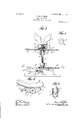
- Figure 1 is a central vertical section of parts of my invention.
- Fig. 2 is a horizontal section taken on the line as a; of Fig. I seen in the direction of the arrow 2.
- Fig. 3 is a detail part-sectional view on an enlarged scale.
- Figs. 4, 5, and 6 are details.
- the immediate object of my present invention is to impart to the car or carrier member of a roundabout, in addition to its usual circular orbital movement, a simultaneous intermittent rotation on its own axis and to provide means whereby said additional movement may be agreeably and safely imparted under conditions insuring requisite economy and practical operativeness.
- A is a central vertically-disposed stationary axle or guide-shaft rigidly fixed to a supporting-frame B.
- B is a rotatory frame sleeved upon axle A and supported by a plurality of rollers, such as 6 rotatably secured thereto and bearing and rotating on a stationary part D, secured to and supported by frame B.
- gear b is a rotatory platform, also sleeved on axle A and secured to, supported by, and rotating with frame B.
- gear-wheel B having spur-gear a and bevel-gear a Gear a meshes with gear a on a power-shaft S, rotated by any preferred means and power.
- a pinion c In bearings b b in frame B rotate and are supported a plurality of vertically-disposed idler-shafts, such as C, which passing through platform b are each loosely or yieldingly coupled, as hereinafter described, with a car or carrier member E. Near the lower extremity of idler-shaft C is secured a pinion c.
- D is provided with an inwardly-disposed continuous rack d, meshing with gear-wheel a, rotatably secured to frame B.
- Gear-Wheel a meshes also with gear-wheel a also rotatably secured to frame B and also meshing with said gear a, sleeved on axle A, whereby leverage is secured and frame B and its connected parts are rotated.
- the outwardlydisposed edge of D is provided with a plurality of segmental racks, such as d.
- levers I I To the lower extremity of idler-shaft C are secured levers I I,radially projecting from C and provided, preferably, with friction-rollers 1" 1*, one of which, 7", is disposed to rotate in a higher plane than 7", as shown in Fig. 3.
- d is an inclined deflector secured to segmental 'uide d and-shaped and disposed substantially as shown in the drawings. (See Figs. 2 and 3.)
- d is an outer guide secured to segmental guide 61 and disposed and shaped substantially as shown in the drawings. (See Figs. 2 and 3.) It will be observed that outer guide 61 is so shaped and proportioned as to contact with and guide roller 1".
- the angle of the arm I, to which said roller 7" is journaled, is so proportioned relatively to the angle of the sides of the teeth of pinion c as to insure in all cases proper presentation of one of said teeth to the first tooth of segmental rack (Z when roller 1" is, as aforesaid, guided by outer guide (F, the adjustmentof said parts being such as to insure that the side of a tooth of said pinion 0 shall make its initial contact with the side of the first tooth of segmental rack (Z at such a presentation as to avoid jamming or looking, as shown particularly in Fig. 5, which ,is a part-sectional detail view of the parts referred to, taken on the line y y of Fig. 3, seen in the direction of the arrow.
- the coupling device shown in Figs. 3 and 4 is constructed and operates as follows, viz: To the top of shaft 0, I secure a circular disk plate M. (Shown in section Fig. 3 plan view Fig. 4.) This disk plate is provided with a plurality of bristles m, rigidly secured thereto and substantially vertically disposed, as shown, the combined disk plate M and its bristles m constituting in substance and effect a disk-backed brush. To the bottom of car E, I secure rigidly a correspondingly-shaped brush e, having its bristles c reversely disposed to the bristles m of the disk plate M and interspersed between said bristles. so that both sets of bristles are mutually interspersed and intercontacted.
- casing 6 will comprise a separate member a as shown in the drawings, though ball-bearings a may be omitted, if preferred, in which case 6 and e will be integral.
- FIG. 6 I have shown another coupling device for accomplishing a similar result, 6 being a casing similar to that shown in Fig. 3 and similarly rigidly secured to car E and rotatably sleeved upon shaft C, h being a head rigidly secured to shaft C and impinging upon leaf-springs s s, secured to casing e*.
- 6 being a casing similar to that shown in Fig. 3 and similarly rigidly secured to car E and rotatably sleeved upon shaft C
- h being a head rigidly secured to shaft C and impinging upon leaf-springs s s, secured to casing e*.
- stationary segmental guides also concentric with said axle intermediate said racks, and levers radially projecting from said idlershaft to intermittently contact with said guides.
Landscapes
- Motorcycle And Bicycle Frame (AREA)
Description
' E. DONALDSON.
ROUNDABOUT. APPLICATION FILED MAR.9.1905.
1 91 so 8 '6 %;@W 69m Q M M 7 I 3,5131% Swan/p 01 Z PATENTED FEB. 27, 1906.
2 SHEETS-SHEET 1.
No. 813,623. PATENTED FEB. 27, 190 E. DONALDSON. ROUNDABOUT.
APPLICATION FILED MAR-9. 1905.
2 SHEBTS-SHEET 2.
' a wuentoz PATENT OFFICE.
EDWIN DONALDSON, OF NEW YORK, N. Y.
ROUNDABOUT- Specification of Letters Patent.
Patented Feb. 27, 1906.
' Applicati fil d March 9.1905. Serial No. 249,325.
To all whom it may concern.-
Be it known that I, EDWIN DONALDSON, a citizen of the United States, and a resident of the borough of Brooklyn, city of New York, county of Kings, and State of New York, have invented certain new and useful Improvements in Roundabouts, of which the following is a specification, reference being had to the accompanying drawings, in which Figure 1 is a central vertical section of parts of my invention. Fig. 2 is a horizontal section taken on the line as a; of Fig. I seen in the direction of the arrow 2. Fig. 3 is a detail part-sectional view on an enlarged scale. Figs. 4, 5, and 6 are details.
The immediate object of my present invention is to impart to the car or carrier member of a roundabout, in addition to its usual circular orbital movement, a simultaneous intermittent rotation on its own axis and to provide means whereby said additional movement may be agreeably and safely imparted under conditions insuring requisite economy and practical operativeness. I attain these objects by means of the various mechanisms hereinafter described and claimed, viz:
A is a central vertically-disposed stationary axle or guide-shaft rigidly fixed to a supporting-frame B.
B is a rotatory frame sleeved upon axle A and supported by a plurality of rollers, such as 6 rotatably secured thereto and bearing and rotating on a stationary part D, secured to and supported by frame B.
b is a rotatory platform, also sleeved on axle A and secured to, supported by, and rotating with frame B. Likewise sleeved on axle A and secured to frame B is gear-wheel B having spur-gear a and bevel-gear a Gear a meshes with gear a on a power-shaft S, rotated by any preferred means and power.
P indicates a stationary platform supported in any convenient manner, from which access may be had to rotatory platform I).
In bearings b b in frame B rotate and are supported a plurality of vertically-disposed idler-shafts, such as C, which passing through platform b are each loosely or yieldingly coupled, as hereinafter described, with a car or carrier member E. Near the lower extremity of idler-shaft C is secured a pinion c.
D is provided with an inwardly-disposed continuous rack d, meshing with gear-wheel a, rotatably secured to frame B. Gear-Wheel a meshes also with gear-wheel a also rotatably secured to frame B and also meshing with said gear a, sleeved on axle A, whereby leverage is secured and frame B and its connected parts are rotated. The outwardlydisposed edge of D is provided with a plurality of segmental racks, such as d.
(1 illustrates one of a plurality of segmental guides stationarily supported intermediately of said segmental racks, but, as shown in the drawings ,at a somewhat lower level.
To the lower extremity of idler-shaft C are secured levers I I,radially projecting from C and provided, preferably, with friction-rollers 1" 1*, one of which, 7", is disposed to rotate in a higher plane than 7", as shown in Fig. 3.
d is an inclined deflector secured to segmental 'uide d and-shaped and disposed substantially as shown in the drawings. (See Figs. 2 and 3.)
d is an outer guide secured to segmental guide 61 and disposed and shaped substantially as shown in the drawings. (See Figs. 2 and 3.) It will be observed that outer guide 61 is so shaped and proportioned as to contact with and guide roller 1". The angle of the arm I, to which said roller 7" is journaled, is so proportioned relatively to the angle of the sides of the teeth of pinion c as to insure in all cases proper presentation of one of said teeth to the first tooth of segmental rack (Z when roller 1" is, as aforesaid, guided by outer guide (F, the adjustmentof said parts being such as to insure that the side of a tooth of said pinion 0 shall make its initial contact with the side of the first tooth of segmental rack (Z at such a presentation as to avoid jamming or looking, as shown particularly in Fig. 5, which ,is a part-sectional detail view of the parts referred to, taken on the line y y of Fig. 3, seen in the direction of the arrow.
The operation of my invention as thus far described is as follows, viz: Power being ap plied to shaft S, frame B,with its connected parts, including car E, is caused to rotate around axle A. When during such rotation pinion 0 reaches one of the segmental racks (Z its cogs mesh with the latter, and idler-shaft C, with its connected parts, is caused to rotate on its own axis, thus imparting to car E, through its coupling therewith, (hereinafter described,) a rotatory movement on its own axis simultaneously with the forward movement of car E in its orbit on a circle concentric with axle A. Said rotatorymovement on its own axis of shaft C and its connected parts is continued until it has passed said segmental rack cl. From thence onward until the next segmental rack is reached shaft 0 ceases to rotate on its own axis, and the rollers r 1" bear against the outwardly-disposed edge of segmental guide d", thus steadymg the movement. As shaft C, with its connected. parts, approaches the beginning of a segmental rack (Z, roller 1' contacts with mclined deflector d whereby .is imparted to shaft C a gently-initiated and gradually-increased rotation, the speed of which at the moment said roller 1" passes beyond said inclined deflector d is substantially equal to that thenceforth imparted to shaft C by segmental rack d, as aforesaid, care being taken to secure this result-by correspondingly proportioning the incline of said deflector 01* and locating it so that its influence upon roller 7' and its connections will terminate approximately simultaneously with the commencement of actuation of pinion c by segmental rack d. a To further relieve the occupants of the car E from undesirable jar at the inception of said rotatory movement of the latter on its own axis, I provide a comparatively loose connection or coupling between said car and shaft 0, together with suitable means for overcoming and compensating lost motion. I prefer to accomplish this by devices illustrated in Figs. 3 and 4, though other devices -might be also employedsuch, for instance,
as that illustrated in Fig. 6.
The coupling device shown in Figs. 3 and 4 is constructed and operates as follows, viz: To the top of shaft 0, I secure a circular disk plate M. (Shown in section Fig. 3 plan view Fig. 4.) This disk plate is provided with a plurality of bristles m, rigidly secured thereto and substantially vertically disposed, as shown, the combined disk plate M and its bristles m constituting in substance and effect a disk-backed brush. To the bottom of car E, I secure rigidly a correspondingly-shaped brush e, having its bristles c reversely disposed to the bristles m of the disk plate M and interspersed between said bristles. so that both sets of bristles are mutually interspersed and intercontacted. I prefer to construct the said bristles of tempered steel wire of such size and length in each instance as to insure sufficient resistance and stability in the connection between the parts thereby affected and at the same time as much elasticity and resiliency as may be desired. To the bottom of the car E is rigidly secured a suitable casing e rotatably journaled or sleeved upon shaft C and supported by frame B, as shown in Fig. 3. To relieve friction, it is preferable to introduce, as shown, ball-bearings e between said casing e and disk plate M, and, if desired, friction may be still further obviated by additional ball bearings 0 in which case casing 6 will comprise a separate member a as shown in the drawings, though ball-bearings a may be omitted, if preferred, in which case 6 and e will be integral.
The operation of my last above-described brush-coupling for obviating jars to the occupants of the car is as follows, viz: When rotation is first imparted to shaft 0, as above described, the bristles of both brushes yield with gradually-increasing resistance until the latter overcomes the inertia of the car and after rotation of shaft C has terminated the inherent resilience of the bristles operates to return them gradually to normal position, thus neutralizing what might otherwise prove disagreeably abrupt shocks or jars to the occupants of'the car.
In Fig. 6 I have shown another coupling device for accomplishing a similar result, 6 being a casing similar to that shown in Fig. 3 and similarly rigidly secured to car E and rotatably sleeved upon shaft C, h being a head rigidly secured to shaft C and impinging upon leaf-springs s s, secured to casing e*. In this instance when rotation is first imparted to shaft C head it tends to rotate and bear against springs s 8 until the inertiaof the car is overcome, thus communicating rotation thereto and without undesirable jar.
By means of my said invention an agreeable and wholesomely exciting additional novel movement may be safely imparted to a roundabout.
Having now described my invention, what I claim as new, and desire to secure by Letters Patent, is the following, viz:
1. In a roundabout, a car for passengers, a
rotatory shaft supporting said car, a yielding connection between said car and said shaft, and means to intermittently rotate said car and shaft around the latters axis.
2. In a roundabout, the combination of a stationary vertically-disposed axle, a rotatory frame sleeved on said axle, a car carried by said frame, an idler-shaft journaled in said frame, springs affixed to said car so as to bear yieldingly against the head of the idlershaft, means to .rotate said idler-shaft upon its own axis, and means to rotate said frame.
3. The combination of a stationary vertically-disposed axle, a rotatory frame sleeved on said axle, an independently-rotatable car supported by said frame, a vertically-disposed idler-shaft journaled in said frame, springs aflixed to said car so as to bear yieldingly against the head of the idler-shaft, means to intermittently rotate said idlershaft, and means to rotate said frame.
4. The combination of a vertically-disposed stationary axle, a rotatory frame sleeved on said axle, means to rotate said frame, an independently-rotatable car supported by an idler-shaft journaled in said frame and yieldingly coupled with said car, a pinion on said idlershaft, a plurality of stationary segmental racks concentric with said axle to intermittently engage said pinion,
stationary segmental guides also concentric with said axle intermediate said racks, and levers radially projecting from said idlershaft to intermittently contact with said guides.
5. The combination of a vertically-disposed stationary axle, a rotatory frame sleeved on said axle, means to rotate said frame, a vertically-disposed idler-shaft journaled in said frame, a pinion on said idlershaft, a plurality of stationary segmental racks concentric with said axle to intermittently engage said pinion, stationary se mental guides also concentric with said ax e intermediate said racks, levers radially projecting from said idler-sl1aft to intermittently contact with said guides so as to prevent rotation of said idler-shaft until said pinion engages with said rack.
6. The combination of a stationary vertically-disposed axle, a rotatory frame sleeved on said axle, means to rotate said frame, an idler-shaft ournaled in said frame, a pinion on said idler-shaft, a segmental rack concentric with said axle to engage said pinion, a lever radially projecting from said idlershaft, and a guide contacting with said lever whereby operative presentation of said pinion to said rack is insured.
EDWIN DONALDSON.
Witnesses:
GEORGE G. MEASURES WILLIAM STAHL.
Priority Applications (1)
| Application Number | Priority Date | Filing Date | Title |
|---|---|---|---|
| US24932505A US813623A (en) | 1905-03-09 | 1905-03-09 | Roundabout. |
Applications Claiming Priority (1)
| Application Number | Priority Date | Filing Date | Title |
|---|---|---|---|
| US24932505A US813623A (en) | 1905-03-09 | 1905-03-09 | Roundabout. |
Publications (1)
| Publication Number | Publication Date |
|---|---|
| US813623A true US813623A (en) | 1906-02-27 |
Family
ID=2882103
Family Applications (1)
| Application Number | Title | Priority Date | Filing Date |
|---|---|---|---|
| US24932505A Expired - Lifetime US813623A (en) | 1905-03-09 | 1905-03-09 | Roundabout. |
Country Status (1)
| Country | Link |
|---|---|
| US (1) | US813623A (en) |
-
1905
- 1905-03-09 US US24932505A patent/US813623A/en not_active Expired - Lifetime
Similar Documents
| Publication | Publication Date | Title |
|---|---|---|
| US813623A (en) | Roundabout. | |
| US1333987A (en) | Windmill | |
| US900820A (en) | Amusement riding device. | |
| US846925A (en) | Amusement device. | |
| US1066396A (en) | Wave-motor. | |
| US938283A (en) | Carousel. | |
| US1156055A (en) | Gearing. | |
| US214292A (en) | Improvement in machines for heading cans | |
| US2239506A (en) | Amusement device | |
| US604614A (en) | Rope-making machine | |
| US864065A (en) | Green-corn husker. | |
| US197438A (en) | Iiviprovement in mechanical movements | |
| US286225A (en) | Mechanism for converting motson | |
| US1146269A (en) | Centrifugal apparatus. | |
| US108915A (en) | Improvement in motive-power apparatus | |
| US470368A (en) | wedgwood | |
| US446022A (en) | Tellurian | |
| US1050430A (en) | Merry-go-round. | |
| USRE5994E (en) | Improvement in corn-shellers | |
| US518675A (en) | Coiler for carding-maghines | |
| US175148A (en) | Improvement in hulling-machines | |
| US1125594A (en) | Water-motor. | |
| US440677A (en) | Liams | |
| US413356A (en) | Spring-motor | |
| US264529A (en) | hallidie |