US8132930B2 - Display device for a tuning apparatus - Google Patents
Display device for a tuning apparatus Download PDFInfo
- Publication number
- US8132930B2 US8132930B2 US12/572,162 US57216209A US8132930B2 US 8132930 B2 US8132930 B2 US 8132930B2 US 57216209 A US57216209 A US 57216209A US 8132930 B2 US8132930 B2 US 8132930B2
- Authority
- US
- United States
- Prior art keywords
- cover
- display device
- light source
- point light
- recited
- Prior art date
- Legal status (The legal status is an assumption and is not a legal conclusion. Google has not performed a legal analysis and makes no representation as to the accuracy of the status listed.)
- Expired - Fee Related, expires
Links
- 239000000463 material Substances 0.000 claims abstract description 17
- 238000009792 diffusion process Methods 0.000 claims abstract description 11
- 238000002955 isolation Methods 0.000 description 3
- 229920003002 synthetic resin Polymers 0.000 description 2
- 239000000057 synthetic resin Substances 0.000 description 2
- NIXOWILDQLNWCW-UHFFFAOYSA-N acrylic acid group Chemical group C(C=C)(=O)O NIXOWILDQLNWCW-UHFFFAOYSA-N 0.000 description 1
- 238000013459 approach Methods 0.000 description 1
- 238000005259 measurement Methods 0.000 description 1
- 230000003287 optical effect Effects 0.000 description 1
- 230000000007 visual effect Effects 0.000 description 1
Images


Classifications
-
- H—ELECTRICITY
- H03—ELECTRONIC CIRCUITRY
- H03J—TUNING RESONANT CIRCUITS; SELECTING RESONANT CIRCUITS
- H03J1/00—Details of adjusting, driving, indicating, or mechanical control arrangements for resonant circuits in general
- H03J1/02—Indicating arrangements
- H03J1/04—Indicating arrangements with optical indicating means
- H03J1/045—Indication of the tuning band, the bandwidth, tone control, the channel number, the frequency, or the like
- H03J1/047—Indication of the tuning band, the bandwidth, tone control, the channel number, the frequency, or the like using electronic means, e.g. LED's
Definitions
- the present invention relates to a display device for a tuning apparatus and a tuning apparatus having a display device, where the display device is an optical system that simulates a mechanical meter.
- Prior displays for tuning apparatuses include displays such as disclosed in Japanese Laid-Open Patent Application Publication (Kokai) Number 2002-323893.
- a tuning guide is configured with a plurality of indicators that are arranged in a row. The higher the pitch that the input musical tone signal is relative to a standard pitch, the further to the right of the center is the indicator that lights. Similarly, the lower the pitch that the input musical tone signal is relative to the standard pitch, the further to the left from the center is the indicator that lights.
- a display device for a tuning apparatus may be configured to increase the visibility and appearance qualities, even if highly bright LEDs are not used. Furthermore, embodiments of the present invention provide a visual appearance of a linear light source without requiring or using light isolation members.
- a display device for a tuning apparatus has a group of point light source units arranged continuously in one row. It is preferable that the point light source units be arranged at a defined constant interval across the row and it is possible to use, for example, LEDs. However, in other embodiments, other suitable intervals (including non-constant intervals) and other suitable types of point light sources may be used.
- a transparent cover is disposed on the front surface of the light emitting sides of each of the point light source units. The cover extends in the longitudinal direction of the row of point light source units and is curved in an arc shape that is perpendicular to that longitudinal direction. The cover does not have a light diffusing material added; in other words, a light diffusing material is not included.
- the cover is formed with a corrugated surface that follows along the arc shape and the corrugated surface is arranged to extend in the along the longitudinal direction of the row of point light sources.
- the cover does not contain a light diffusing material, the diffusion of the light in all directions through the cover is suppressed, and the diffusion of the light in the longitudinal direction of the arrangement of the point light source units is inhibited. Accordingly, in certain embodiments of the present invention, it is not necessary to dispose isolating members between adjacent point light source units.
- the light from the point light sources has the appearance of a linear shape in the direction that is perpendicular to the longitudinal direction in which the point light sources are arrayed, due to the corrugated surface that is formed on the cover.
- the appearance that is exhibited is as a needle shaped display, appearing as if a single linear light source were used.
- the shape of the corrugated surface of the cover may be configured such that the cover forms a plurality of isosceles triangle shapes at least within a specified range from the peak of the arc shape.
- the plurality of isosceles triangles are disposed such that a corresponding plurality of radii that extend radially from the center of the cover pass through the apices of the triangles.
- the shape of the corrugated surface of the cover may be configured such that, a plurality of triangles are formed at least within a specified range from the peak of the arc shape. Those triangles have sides that are approximately horizontal and approximately vertical. As a result, the portion of the light from each point light source that is oriented toward the roughly horizontal side is virtually completely reflected and there is no leakage through to outside the cover. In addition, the portion of the light from each point light source that is oriented toward the roughly vertical side passes through the roughly vertical side and is refracted such that the light approaches the vertical side. As a result, the light from the point light source has the appearance of a more linear form.
- the shape of the corrugated surface of the cover can be configured such that the lengths of the approximately horizontal sides that are close to the peak of the arc shape are made short compared to the lengths of the approximately vertical sides. As a result, it is possible to make the light that is completely reflected by the approximately horizontal sides less and the light that passes through the approximately vertical sides greater. In that manner, it is possible to increase the amount of light that appears a linear form.
- the surface of the side of the cover that faces the point light source units may be configured with an arc shaped cross section.
- the inside of the cover can be made hollow, for example to reduce the weight of the cover.
- each of the point light source units may be positioned at the center of the arc shape of the cover. As a result, light from the point light source units may strike the arc shaped portion uniformly, such that the lengths of the linear form lights that are viewable through the cover have a more uniform appearance.
- a linear form display may be provided that corresponds to the display of a mechanical meter while using an array of point light source units. Moreover, even when the point light source units are arranged in relatively close proximity to each other, it is possible to readily visually determine which of the point light source units emits light, where the emitted light appears in a linear form without blurring of the linear form display. In addition, it is possible to simplify the configuration without the need to dispose isolation members between adjacent point light source units.
- FIG. 1 is a plane drawing of a tuning apparatus according to an embodiment of the present invention
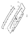
- FIG. 2 is a partially exploded assembly drawing of the tuning apparatus of FIG. 1 ;
- FIG. 3 is a partially exploded assembly drawing of a display section for the tuning apparatus of FIG. 1 ;
- FIG. 4 is a drawing showing a partial perspective and expanded view of the display section of FIG. 3 ;
- FIG. 5 is a longitudinal section lateral drawing of an LED cover for the display section of FIG. 3 ;
- FIGS. 6 a - c are drawings for an explanation of refraction of the light in the LED cover of FIG. 5 ;
- FIGS. 7 a - d show a front view drawing, a plane drawing, a bottom view drawing, and a left lateral drawing, respectively, of another example of an LED cover of FIG. 5 .
- the tuning apparatus is for tuning of an electronic stringed instrument and is shown in FIG. 1 and FIG. 2 .
- the tuning apparatus has a main body section 2 that has a longitudinal dimension in the horizontal direction of FIG. 1 .
- the tuning apparatus may be placed at or near the feet of the instrument operator in a position to allow the operator to visually confirm the state of the tuning from the apparatus.
- a flat tuning button 4 , a mode button 6 , a tuner on/off switch 8 , a pitch button 10 , and a display button 12 are arranged in a row, in that order, at the front (lower portion in FIG. 1 ) of a top surface of the main body section 2 .
- the tuning on/off indicator 14 is disposed next to the tuner on/off switch 8 .
- the display section 16 is disposed in a position at the back (upper portion in FIG. 1 ) of the top surface of the main body section 2 .
- An electronic string instrument to be tuned may be connected to an input jack (not show) on the tuning apparatus and the mode button 6 may be pushed and the tuning mode selected.
- the tuning modes there are for example, the Chromatic mode that tunes the musical intervals of all 12 tones in half tone steps, the Guitar mode that does the tuning with the guitar string numbers, the Bass mode that does the tuning with the bass string numbers, the Drop D mode that does drop D tuning of the guitar, and the DADGAD mode that does DADGAD tuning of the guitar.
- the tuner on/off switch 8 is operated to turn the tuning apparatus on. When the tuning apparatus is turned on, the tuner on/off indicator 14 lights. In this state, a single tone may be generated by the electronic stringed instrument.
- the meter 20 is an electronic meter, but is configured such that a linear dimension and form of the display resembles the display of a mechanical type needle. In those cases where the tone interval is low, the linear display indicator is further to the left than the middle of the meter 20 ; and in those cases where the tone interval is high, the linear display indicator is further to the right than the middle of the meter 20 . In those cases where the tone intervals are in agreement, the display of the linear display indicator is in the middle of the meter 20 .
- the left side of the tuning guide indicator 22 in FIG. 1 lights in those cases where the tone interval is low, while the right side lights in those cases where the tone interval is high, and both light when the tone intervals match.
- the tuning apparatus may have various functions in addition to those described herein.
- FIG. 2 shows the tuning apparatus in a the state in which the upper cover 24 , which covers the display 16 , and the button cover portion (not shown in FIG. 2 ) which covers the flat tuning button 4 , the mode button 6 , the pitch button 10 , and the display button 12 , have been removed.
- the upper cover 24 may be made of any suitable material, including, but not limited to a translucent material such as, but not limited to acrylic that has been colored at appropriate locations.
- the upper cover 24 is attached on the main body unit 2 over and covering the note name and string number indicator 18 , the meter 20 , and the tuning guide indicator 22 .
- each of the switches, the flat tuning button 4 , the mode button 6 , the pitch button 10 , and the display button 12 has an LED that shows the operating state of the display button built into the main body section 2 .
- the display section 16 has a point light source unit group, for example but not limited to an LED group, with a plurality of point light source units, for example but not limited to a total of 101 LED elements 28 disposed in a row at a specified spacing interval (for example, but not limited to 3.08 mm).
- a plurality of LED point light source units 28 are disposed on one side of a rectangular printed circuit board 26 .
- These LEDs 28 may be chip LEDs in which the light emitting section is a point light emitter and, in the FIG. 3 embodiment, are arranged in a line that forms an arc shape.
- a cover, for example, the LED cover 30 , that covers all of the LEDs 28 is attached to the printed circuit board 26 over and in front of the light emitting side of the LEDs 28 .
- the LED cover 30 may be made of any suitable material including, but not limited to a synthetic resin, that does not have a light diffusion material added. Thus, the LED cover 30 does not contain (is free of) a light diffusion material.
- a suitable synthetic resin may be a material that is uncolored and transparent, through which light is transmitted such as, for example but not limited to ABS.
- the LED cover 30 is formed in an arc shape along its longitudinal dimension, corresponding to and matching the arc-shaped line of the LEDs 28 . The side shape of the LED cover 30 , as is shown in FIG. 4 and FIG.
- the inside of the LED cover 30 is hollow and the center of the semicircle is, as is shown in FIG. 4 , positioned above the center of each of the LEDs 28 .
- the note name and string number indicator 18 and the tuning guide indicator 22 also may be attached to the printed circuit board 26 .
- the printed circuit board 26 is arranged in the main body section 2 so that the LED cover 30 is positioned in a window 31 on the top surface of the main body section 2 .
- a plurality of corrugations 32 are formed on the outer surface of the LED cover 30 , around the semicircle arc.
- the corrugation 32 extends from one edge of the LED cover 30 to the other edge, along the longitudinal dimension of the cover 30 .
- the corrugation 32 is arranged continuously, with the shape of their side surfaces forming generally triangular shaped portions (in cross section or side view of FIG. 5 ) having their apices protruding outward from the outer surface of the LED cover 30 .
- the apices of the generally triangular shaped portions of the corrugation 32 and the junctions of the adjacent generally triangular shapes on the outer surface side of the LED cover 30 may be rounded as shown in FIGS. 4 and 5 .
- the generally triangular shapes of the corrugation 32 are configured with the substantially equal side lengths for each side that is connected to the apices. Moreover, the generally triangular shapes may be disposed at an equal pitch in the region “a” in a specified angular range on both sides of a perpendicular line “l” extending from the center of the LED cover 30 . In one example embodiment, the generally triangular shapes are arranged at a pitch of 0.3 mm. However, further embodiments may include generally triangular shapes that are arranged at a pitch of from about 0.25 to about 0.5 mm.
- the sides of the generally triangular shapes in the corrugation that are at the two opposite ends of the region “a” are generally parallel and, for example, are at angle that is slightly greater than one degree with respect to perpendicular line “l”.
- the lengths of the two sides of each of the generally triangular shapes in the corrugation are about equal.
- the side of each generally triangular shape that is more distant from the perpendicular line “l” is generally vertical and is arranged at a generally equal pitch with the corresponding side of each of the other generally triangular shaped portions in region “b.”.
- the pitch in region “b” may be about the same as the pitch of the region “a,” so that an angle of, for example, one degree is made by the generally vertical side of each generally triangular shaped portion in region “b” with respect to the perpendicular line “l.”
- the generally vertical side of each generally triangular shape in region “b” is not as long as the corresponding sides of the generally triangular shapes in region c, discussed below, but is longer than the other side of the generally triangular shape in region “c.”
- the position of the end of the region “b” (the position in region “b” that is most distant from the perpendicular line “l”) is set so that the lengths of the two sides of the generally triangular shape at that position are about equal and, at the same time, is a position where it becomes nearly impossible for the side most distant from the perpendicular line “l” to be vertical.
- the lengths of the two sides of each of the generally triangular shapes in the corrugation 32 are different, where the side that is more distant from the perpendicular line “l” is generally vertical.
- the pitch of the sides furthest from the perpendicular line “l” of the generally triangular shapes in region “c” is different than the pitch in region “b,” such that, for example, an angle of one degree with respect to the perpendicular line “l” is made.
- the pitch is set such that as there is a progression in the distance from the perpendicular line “l,” there is a gradual increase in the pitch even more than in the regions “a” and “b.” Accordingly, the generally triangular shapes in the region “c” each comprise a long side that is positioned about vertical and a short side that is positioned about horizontal.
- the corrugation 32 of the region “a” can be made, as is shown in FIG. 6( a ), to have a lateral shape that closely approximates the lateral shape of a plurality of isosceles triangles that extend continuously on the outer surface of the LED cover 30 .
- the corrugations 32 of the region “b” can be made, as is shown in FIG. 6( b ), to closely approximate a pluralities of isosceles triangle that are each positioned with one side about vertical.
- the corrugations of the region “c” can be made, as is shown in FIG. 6( c ), to closely approximate a plurality of triangles, each having a longer side that is positioned about vertical and a shorter side that is positioned about horizontal.
- the portion of the light that has impacted directly on the inner surface of the LED cover 30 in region “a” is beamed, as is shown in FIG. 6( a ), toward the two sides of the generally triangular shapes in the corrugation 32 .
- the angle of refraction ⁇ of the light that is emitted into the air from the LED cover 30 is greater than the angle of incidence ⁇ . Accordingly, the portion of the light that is incident on the region “a” is beamed generally upward.
- the length of the generally horizontal sides is relatively short, the amount of light that is completely reflected by the roughly horizontal sides is relatively low and, overall, the light that is refracted by the roughly vertical sides and beamed upward is relatively great.
- a portion of the light emitted from the LEDs 29 is also beamed toward and along the longitudinal dimension direction of the LED cover 30 .
- the amount of light that is incident into the LED cover 30 can be relatively small.
- no diffusion material is contained in the LED cover 30 , there is not much diffusion of the light that is incident on the LED cover 30 .
- the light that is viewable through the LED cover 30 appears in a form of a line that is perpendicular to the long direction of the LED cover 30 with preferred visibility when the tuning apparatus is viewed from above. Accordingly, by changing the LEDs 28 with which light is emitted in a consecutive order, it is possible to simulate a condition in which the needle of a mechanical meter moves.
Landscapes
- Illuminated Signs And Luminous Advertising (AREA)
- Auxiliary Devices For Music (AREA)
Abstract
Description
Claims (21)
Applications Claiming Priority (2)
| Application Number | Priority Date | Filing Date | Title |
|---|---|---|---|
| JP2009-019378 | 2009-01-30 | ||
| JP2009019378A JP2010175906A (en) | 2009-01-30 | 2009-01-30 | Display unit of tuning device |
Publications (2)
| Publication Number | Publication Date |
|---|---|
| US20100195324A1 US20100195324A1 (en) | 2010-08-05 |
| US8132930B2 true US8132930B2 (en) | 2012-03-13 |
Family
ID=42397559
Family Applications (1)
| Application Number | Title | Priority Date | Filing Date |
|---|---|---|---|
| US12/572,162 Expired - Fee Related US8132930B2 (en) | 2009-01-30 | 2009-10-01 | Display device for a tuning apparatus |
Country Status (2)
| Country | Link |
|---|---|
| US (1) | US8132930B2 (en) |
| JP (1) | JP2010175906A (en) |
Families Citing this family (1)
| Publication number | Priority date | Publication date | Assignee | Title |
|---|---|---|---|---|
| CN105280108B (en) * | 2015-12-03 | 2018-11-13 | 长沙信元电子科技有限公司 | arc-shaped L ED screen and factory manufacturing and field installation method thereof |
Citations (1)
| Publication number | Priority date | Publication date | Assignee | Title |
|---|---|---|---|---|
| JP2002323893A (en) | 2001-04-24 | 2002-11-08 | Roland Corp | Music control device |
Family Cites Families (6)
| Publication number | Priority date | Publication date | Assignee | Title |
|---|---|---|---|---|
| JPS61152914U (en) * | 1985-03-14 | 1986-09-22 | ||
| JP4661735B2 (en) * | 2005-09-21 | 2011-03-30 | 日本ビクター株式会社 | Surface light source device |
| JP4706428B2 (en) * | 2005-10-19 | 2011-06-22 | ヤマハ株式会社 | Tuner |
| JP2007193156A (en) * | 2006-01-20 | 2007-08-02 | Yamaha Corp | Electronic musical instrument with tuning device |
| JP2010165572A (en) * | 2009-01-16 | 2010-07-29 | Sony Corp | Planar light emitting device, panel, and display device |
| WO2012063758A1 (en) * | 2010-11-12 | 2012-05-18 | シャープ株式会社 | Lighting device and display device |
-
2009
- 2009-01-30 JP JP2009019378A patent/JP2010175906A/en active Pending
- 2009-10-01 US US12/572,162 patent/US8132930B2/en not_active Expired - Fee Related
Patent Citations (1)
| Publication number | Priority date | Publication date | Assignee | Title |
|---|---|---|---|---|
| JP2002323893A (en) | 2001-04-24 | 2002-11-08 | Roland Corp | Music control device |
Also Published As
| Publication number | Publication date |
|---|---|
| JP2010175906A (en) | 2010-08-12 |
| US20100195324A1 (en) | 2010-08-05 |
Similar Documents
| Publication | Publication Date | Title |
|---|---|---|
| US7188989B2 (en) | Light guide plate and support unit for the same | |
| US7086768B2 (en) | Illumination device and illuminated input device | |
| EP0029638B1 (en) | Laminar light guide and an instrument display means comprising such a light guide | |
| US7654679B2 (en) | Illumination system | |
| US7588338B2 (en) | Keyboard equipped with a backlight structure | |
| US20110310615A1 (en) | Light emitting apparatus, surface light source apparatus, display apparatus, and luminous flux control member | |
| JP5835559B2 (en) | Pointer type display device | |
| CN104321810A (en) | Edge-lit flat panel repetitive lighting fixture | |
| JPWO2009128516A1 (en) | Display device | |
| CN103153411B (en) | Decorative devices and game consoles | |
| CN105911631B (en) | Light guide and light-emitting device | |
| US8132930B2 (en) | Display device for a tuning apparatus | |
| JP2011113695A (en) | Illumination device and electronic apparatus | |
| JP6150607B2 (en) | Light emitting device | |
| JP6232670B2 (en) | Dial illumination structure | |
| JP5384924B2 (en) | Light guide plate | |
| JP4223533B2 (en) | Flat lighting device | |
| US6953885B2 (en) | Tuning device | |
| JP2009266802A (en) | Display | |
| JP5190245B2 (en) | Luminous pointer instrument | |
| US20060227261A1 (en) | Light guide plate and backlight module using the same | |
| JP6135921B2 (en) | Display member and display device | |
| CN222839793U (en) | Sound producing device and vehicle | |
| JP2001242808A (en) | Display panel | |
| US20250264662A1 (en) | Optical coupler for a lighting system, in particular for a vehicle passenger compartment |
Legal Events
| Date | Code | Title | Description |
|---|---|---|---|
| AS | Assignment |
Owner name: ROLAND CORPORATION, JAPAN Free format text: ASSIGNMENT OF ASSIGNORS INTEREST;ASSIGNOR:WADA, NORIHIKO;REEL/FRAME:023316/0159 Effective date: 20090929 |
|
| FEPP | Fee payment procedure |
Free format text: PAYOR NUMBER ASSIGNED (ORIGINAL EVENT CODE: ASPN); ENTITY STATUS OF PATENT OWNER: LARGE ENTITY |
|
| ZAAA | Notice of allowance and fees due |
Free format text: ORIGINAL CODE: NOA |
|
| ZAAB | Notice of allowance mailed |
Free format text: ORIGINAL CODE: MN/=. |
|
| STCF | Information on status: patent grant |
Free format text: PATENTED CASE |
|
| FPAY | Fee payment |
Year of fee payment: 4 |
|
| MAFP | Maintenance fee payment |
Free format text: PAYMENT OF MAINTENANCE FEE, 8TH YEAR, LARGE ENTITY (ORIGINAL EVENT CODE: M1552); ENTITY STATUS OF PATENT OWNER: LARGE ENTITY Year of fee payment: 8 |
|
| FEPP | Fee payment procedure |
Free format text: MAINTENANCE FEE REMINDER MAILED (ORIGINAL EVENT CODE: REM.); ENTITY STATUS OF PATENT OWNER: LARGE ENTITY |
|
| LAPS | Lapse for failure to pay maintenance fees |
Free format text: PATENT EXPIRED FOR FAILURE TO PAY MAINTENANCE FEES (ORIGINAL EVENT CODE: EXP.); ENTITY STATUS OF PATENT OWNER: LARGE ENTITY |
|
| STCH | Information on status: patent discontinuation |
Free format text: PATENT EXPIRED DUE TO NONPAYMENT OF MAINTENANCE FEES UNDER 37 CFR 1.362 |
|
| FP | Lapsed due to failure to pay maintenance fee |
Effective date: 20240313 |