US8130622B2 - Optical pickup apparatus having multi-sectional polarizer - Google Patents
Optical pickup apparatus having multi-sectional polarizer Download PDFInfo
- Publication number
- US8130622B2 US8130622B2 US12/761,495 US76149510A US8130622B2 US 8130622 B2 US8130622 B2 US 8130622B2 US 76149510 A US76149510 A US 76149510A US 8130622 B2 US8130622 B2 US 8130622B2
- Authority
- US
- United States
- Prior art keywords
- light
- pickup apparatus
- optical pickup
- objective lens
- optical
- Prior art date
- Legal status (The legal status is an assumption and is not a legal conclusion. Google has not performed a legal analysis and makes no representation as to the accuracy of the status listed.)
- Expired - Fee Related
Links
Images


Classifications
-
- G—PHYSICS
- G11—INFORMATION STORAGE
- G11B—INFORMATION STORAGE BASED ON RELATIVE MOVEMENT BETWEEN RECORD CARRIER AND TRANSDUCER
- G11B7/00—Recording or reproducing by optical means, e.g. recording using a thermal beam of optical radiation by modifying optical properties or the physical structure, reproducing using an optical beam at lower power by sensing optical properties; Record carriers therefor
- G11B7/12—Heads, e.g. forming of the optical beam spot or modulation of the optical beam
- G11B7/135—Means for guiding the beam from the source to the record carrier or from the record carrier to the detector
- G11B7/1398—Means for shaping the cross-section of the beam, e.g. into circular or elliptical cross-section
-
- G—PHYSICS
- G11—INFORMATION STORAGE
- G11B—INFORMATION STORAGE BASED ON RELATIVE MOVEMENT BETWEEN RECORD CARRIER AND TRANSDUCER
- G11B7/00—Recording or reproducing by optical means, e.g. recording using a thermal beam of optical radiation by modifying optical properties or the physical structure, reproducing using an optical beam at lower power by sensing optical properties; Record carriers therefor
- G11B7/12—Heads, e.g. forming of the optical beam spot or modulation of the optical beam
- G11B7/135—Means for guiding the beam from the source to the record carrier or from the record carrier to the detector
- G11B7/1365—Separate or integrated refractive elements, e.g. wave plates
-
- G—PHYSICS
- G11—INFORMATION STORAGE
- G11B—INFORMATION STORAGE BASED ON RELATIVE MOVEMENT BETWEEN RECORD CARRIER AND TRANSDUCER
- G11B7/00—Recording or reproducing by optical means, e.g. recording using a thermal beam of optical radiation by modifying optical properties or the physical structure, reproducing using an optical beam at lower power by sensing optical properties; Record carriers therefor
- G11B7/12—Heads, e.g. forming of the optical beam spot or modulation of the optical beam
- G11B7/125—Optical beam sources therefor, e.g. laser control circuitry specially adapted for optical storage devices; Modulators, e.g. means for controlling the size or intensity of optical spots or optical traces
- G11B7/127—Lasers; Multiple laser arrays
- G11B7/1275—Two or more lasers having different wavelengths
-
- G—PHYSICS
- G11—INFORMATION STORAGE
- G11B—INFORMATION STORAGE BASED ON RELATIVE MOVEMENT BETWEEN RECORD CARRIER AND TRANSDUCER
- G11B7/00—Recording or reproducing by optical means, e.g. recording using a thermal beam of optical radiation by modifying optical properties or the physical structure, reproducing using an optical beam at lower power by sensing optical properties; Record carriers therefor
- G11B7/12—Heads, e.g. forming of the optical beam spot or modulation of the optical beam
- G11B7/135—Means for guiding the beam from the source to the record carrier or from the record carrier to the detector
- G11B7/1365—Separate or integrated refractive elements, e.g. wave plates
- G11B7/1367—Stepped phase plates
-
- G—PHYSICS
- G11—INFORMATION STORAGE
- G11B—INFORMATION STORAGE BASED ON RELATIVE MOVEMENT BETWEEN RECORD CARRIER AND TRANSDUCER
- G11B7/00—Recording or reproducing by optical means, e.g. recording using a thermal beam of optical radiation by modifying optical properties or the physical structure, reproducing using an optical beam at lower power by sensing optical properties; Record carriers therefor
- G11B2007/0003—Recording, reproducing or erasing systems characterised by the structure or type of the carrier
- G11B2007/0006—Recording, reproducing or erasing systems characterised by the structure or type of the carrier adapted for scanning different types of carrier, e.g. CD & DVD
Definitions
- the present general inventive concept relates to an optical pickup apparatus, and more particularly, to an optical pickup apparatus having a multi-sectional polarizer.
- An optical pickup apparatus is used to record information onto an optical disc using light or to reproduce the information recorded on the optical disc.
- the optical pickup apparatus includes an objective lens to focus light onto an optical disc.
- Representative examples of an optical disc may include a Compact Disc (CD) using a laser with a wavelength of 780 nm, and a Digital Versatile Disc (DVD) using a laser with a wavelength of 650 nm.
- a Blu-ray Disc (BD) using a blue-violet laser with a wavelength of about 405 nm has been used.
- a blu-ray disc uses light with a shorter wavelength compared to a CD and a DVD, and accordingly a numerical aperture (NA) of an objective lens for the blu-ray disc is greater than a numerical aperture of an objective lens for the CD and a numerical aperture of an objective lens for the DVD.
- NA numerical aperture
- the objective lens for the CD has a numerical aperture of 0.45
- the objective lens for the DVD has a numerical aperture of 0.55
- the objective lens for the blu-ray disc has a numerical aperture of 0.85.
- the numerical aperture refers to a parameter defined as a combination of an external diameter and a focal distance of a lens.
- the lens becomes more convex. Accordingly, in order to minimize an optical aberration, a lens having a greater numerical aperture requires more precise processing.
- the objective lens for the blu-ray disc having a numerical aperture significantly greater than the numerical aperture of the objective lens for the CD and numerical aperture of the objective lens for the DVD needs to be manufactured through processes with high precision. Accordingly, the objective lens for the blu-ray disc may have a narrow allowable range of manufacturing tolerances, and thus costs of an optical pickup apparatus for the blu-ray disc may increase.
- An optical pickup apparatus may be compatible with a CD, a DVD and a blu-ray disc, so as to be employed for the use of the CD, the DVD and the blu-ray disc.
- This compatible optical pickup apparatus may include a compatible objective lens to be applied to all the CD, the DVD and the blu-ray disc.
- a working distance (WD) between the compatible objective lens and the CD should be ensured to be equal to or greater than a default value, for example 0.4 mm. If the working distance does not reach the default value, it is highly likely that inadvertent contact between the CD and the objective lens occurs during working, which results in damage to the CD or the objective lens.
- a focal distance is substantially equal to or greater than 2.2 mm so that the working distance between the CD and the compatible objective lens may be ensured to be equal to or greater than 0.4 mm.
- the compatible objective lens having the focal distance of about 2.2 mm with respect to the blu-ray disc is contrary to a demand for slimness of the optical pickup apparatus, taking into consideration that an objective lens currently used in a slim optical pickup apparatus has a focal distance of about 1.4 mm with respect to the blu-ray disc.
- Example embodiments of the present general inventive concept provide an optical pickup apparatus to widen an allowable range of manufacturing tolerances while maintaining a recording density at the same level as before. Also, example embodiments of the present general inventive concept provide a compatible optical pickup apparatus to meet a demand for slimness while maintaining a reference working distance (WD) with respect to a Compact Disc (CD).
- WD working distance
- CD Compact Disc
- an optical pickup apparatus including a light generating unit to generate a light to record or reproduce information, an objective lens to focus the light generated from the light generating unit onto a disk, and a multi-sectional polarizer positioned along a light path between the light generating unit and the objective lens and divided into a plurality of sectors having their individual optical axes.
- the multi-sectional polarizer may be manufactured with a half-wavelength plate.
- the plurality of sectors of the multi-sectional polarizer may have the same central angle.
- the number of the plurality of sectors of the multi-sectional polarizer may be an even-number.
- Optical axes of two sectors facing each other may be parallel to each other.
- Optical axes of two sectors facing each other may be perpendicular to each other.
- the multi-sectional polarizer may face the objective lens.
- the light generating unit may include at least one of a light source for a Compact Disc (CD), a light source for a Digital Versatile Disc (DVD) and a light source for a Blu-ray Disc.
- a light source for a Compact Disc CD
- a light source for a Digital Versatile Disc DVD
- a light source for a Blu-ray Disc Blu-ray Disc
- the light generating unit may include the light source for a blu-ray disc only.
- a numerical aperture (NA) of the objective lens may be equal to or greater than 0.70 and less than 0.85.
- the light generating unit may include a light source for a CD, a light source for a DVD and a light source for a blu-ray disc.
- the objective lens may be a compatible objective lens compatible with a CD, a DVD and a blu-ray disc.
- the objective lens may have a numerical aperture of 0.76 with respect to a blu-ray disc, a numerical aperture of 0.53 with respect to a DVD, and a numerical aperture of 0.44 with respect to a CD.
- the light generating unit may include a two-wavelength light source module comprising the light source for the CD and the light source for the DVD, and a light source module for a blu-ray disc comprising the light source for the blu-ray disc.
- the optical pickup apparatus may include a photodetector to detect the light reflected from the disk, a first beam splitter to reflect a light emitted from the two-wavelength light source module and to transmit a light emitted from the light source module for the blu-ray disc, and a second beam splitter to reflect the light incident from the first beam splitter toward the objective lens and to transmit the light incident from the objective lens toward the photodetector.
- the second beam splitter may reflect one half of the P-polarized light and transmit the other half of the P-polarized light.
- a data storage apparatus including a disc to store data and an optical pickup apparatus to perform at least one of reading data from the disc and writing data to the disc.
- the optical pickup apparatus may include a multi-sectional polarizer including at least two sections each having a respective optical axis to polarize light passing through the multi-sectional polarizer to the disc into at least two different orientations according to the respective optical axes.
- the disc may be one of a CD, a DVD, and a blu-ray disc.
- the optical device may further include a controller to control the optical pickup to read data from and write data to the disc.
- FIG. 1 is a schematic view illustrating an optical pickup apparatus according to a first exemplary embodiment of the present general inventive concept
- FIG. 2 is a schematic view of a first embodiment of a multi-sectional polarizer according to the present general inventive concept
- FIG. 3 is a schematic view of a second embodiment of a multi-sectional polarizer according to the present general inventive concept
- FIG. 4 is a view explaining a direction of an optical axis in the first embodiment of the multi-sectional polarizer according to the present general inventive concept
- FIG. 5 is a view explaining a direction of an optical axis in the second embodiment of the multi-sectional polarizer according to the present general inventive concept
- FIG. 6 illustrate operations of a multi-sectional polarizer according to the present general inventive concept
- FIG. 7 is a schematic view illustrating a compatible optical pickup apparatus according to a second exemplary embodiment of the present general inventive concept
- FIGS. 8A and 8B illustrate multi-sectional polarizers according to the present general inventive concept.
- FIG. 9 illustrates an optical device according to the present general inventive concept.
- the optical pickup apparatus 100 is exemplified as an optical pickup apparatus for a Blu-ray Disc, and the following description of the first exemplary embodiment of the present general inventive concept may also be applied to an optical pickup apparatus for a Compact Disc (CD) or an optical pickup apparatus for a Digital Versatile Disc (DVD).
- CD Compact Disc
- DVD Digital Versatile Disc
- FIG. 1 schematically illustrates the optical pickup apparatus 100 according to the first exemplary embodiment of the present general inventive concept.
- the optical pickup apparatus 100 includes a light generating unit 110 , a beam splitter 120 , a collimating lens 130 , a reflective mirror 140 , a multi-sectional polarizer 150 , an objective lens 160 , a sensor lens 170 and a photodetector 180 .
- the light generating unit 110 can generate light that is applicable to an optical disc D such as a blu-ray disc. Accordingly, the light generating unit 110 can include an optical module for the blu-ray disc 111 , which has a light source (not illustrated) to emit light with a wavelength of about 405 nm.
- the light source included in the optical module for the blu-ray disc 111 may be implemented as a laser diode.
- the light generated from the light generating unit 110 is P-polarized light having a single vibration direction, according to essential characteristics of a laser.
- the beam splitter 120 can reflect part of the light generated from the light generating unit 110 toward the reflective mirror 140 . Additionally, the beam splitter 120 can transmit part of light reflected from the optical disc D toward the photodetector 180 .
- the beam splitter 120 has properties to reflect one half of the P-polarized light and transmit the other half when the P-polarized light enters. Accordingly, the beam splitter 120 can reflect one half of the light generated from the light generating unit 110 , and can transmit one half of the light reflected from the optical disc D. Thus, only a quarter of the light generated from the light generating unit 110 may reach the photodetector 180 . However, an amount of light generated from the light generating unit 110 may be appropriately regulated, and thus it is possible to prevent problems such as non-detection of light or false detection of light.
- the collimating lens 130 is an element to convert light into parallel light.
- the collimating lens 130 may be disposed between the beam splitter 120 and the reflective mirror 140 .
- the collimating lens 130 can convert the light generated from the light generating unit 110 into parallel light, before the generated light is incident onto the objective lens 160 .
- the reflective mirror 140 may be disposed between the collimating lens 130 and the multi-sectional polarizer 150 .
- the reflective mirror 140 can reflect the light transferred from the beam splitter 120 , toward the objective lens 160 . Additionally, the reflective mirror 140 can reflect the light, which is reflected from the optical disc D and passes through the objective lens 160 and the multi-sectional polarizer 150 , toward the beam splitter 120 .
- the multi-sectional polarizer 150 may be placed on a light path between the light generating unit 110 and the objective lens 160 .
- the multi-sectional polarizer 150 may be disposed between the reflective mirror 140 and the objective lens 160 , so as to face the objective lens 160 .
- the multi-sectional polarizer 150 is an element to change the polarization status of light, and has an optical anisotropy. Additionally, the multi-sectional polarizer 150 may be manufactured with a half-wavelength plate to generate a phase difference of 180°. The multi-sectional polarizer 150 will be described in greater detail below.
- the objective lens 160 can focus the light generated from the light generating unit 110 onto the optical disc D.
- a numerical aperture (NA) of the objective lens 160 is less than or equal to a typical value.
- an objective lens for the blu-ray disc typically has a numerical aperture of 0.85, but the objective lens 160 has a numerical aperture in a range between 0.70 and 0.85 (namely, 0.70 ⁇ NA ⁇ 0.85).
- the sensor lens 170 may be a concave lens, and may be disposed between the beam splitter 120 and the photodetector 180 .
- the sensor lens 170 can convert the light reflected from the optical disc D into light detectable by the photodetector 180 .
- the photodetector 180 can detect the light reflected from the optical disc D, and convert the detected light into an electrical signal. Information recorded on the optical disc D and a control signal required to operate the optical pickup apparatus 100 can be obtained from the electrical signal.
- the multi-sectional polarizer 150 is now described in greater detail with reference to FIGS. 2 to 6 .
- FIG. 2 is a schematic view of a first embodiment of a multi-sectional polarizer according to the present general inventive concept
- FIG. 3 is a schematic view of a second embodiment of a multi-sectional polarizer according to the present general inventive concept
- FIG. 4 is a view explaining a direction of an optical axis in the first embodiment of the multi-sectional polarizer according to the present general inventive concept
- FIG. 5 is a view explaining a direction of an optical axis in the second embodiment of the multi-sectional polarizer according to the present general inventive concept
- FIG. 6A is a view explaining operations of a multi-sectional polarizer according to the present general inventive concept.
- a multi-sectional polarizer 150 A according to the first exemplary embodiment of the present general inventive concept and a multi-sectional polarizer 150 B according to the second exemplary embodiment of the present general inventive concept can take the form of disks.
- Each of the multi-sectional polarizers 150 A and 1506 can be divided into a plurality of fan-shaped sectors having the same central angle.
- the multi-sectional polarizers 150 A and 1506 are not limited to the disk shape, and the plurality of sectors is not limited to the fan shape.
- the number of sectors included in the multi-sectional polarizers 150 A and 150 B is an even-number, and may desirably be equal to or greater than 4.
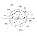
- each of the multi-sectional polarizers 150 A and 1506 has eight sectors.
- reference numerals 150 A 1 , 150 A 2 , . . . , 150 A 7 and 150 A 8 are successively assigned to the eight sectors of the multi-sectional polarizer 150 A counterclockwise
- reference numerals 150 B 1 , 150 B 2 , . . . , 150 B 7 and 150 B 8 are successively assigned to the eight sectors of the multi-sectional polarizer 150 B counterclockwise.
- each arrow illustrated on each sector indicates a direction of an optical axis of a sector.
- optical axes of two sectors facing each other are parallel to each other.
- an optical axis of a second sector 150 A 2 is parallel to an optical axis of a sixth sector 150 A 6 .
- optical axes of two sectors facing each other are perpendicular to each other.
- an optical axis of a third sector 150 B 3 is perpendicular to an optical axis of a seventh sector 150 B 7 .
- the direction of the optical axis for each sector of the multi-sectional polarizers 150 A and 150 B may be represented by equations.
- the multi-sectional polarizers 150 A and 150 B which each have the plurality of sectors having their individual optical axes, can convert P-polarized light P that is one of linearly polarized light into concentric linearly polarized light C 1 formed by combining a plurality of linearly polarized light beams which vibrate in tangential directions of concentric circles, and can convert S-polarized light S that is the other of linearly polarized light into concentric linearly polarized light C 2 formed by combining a plurality of linearly polarized light beams which vibrate in radial directions of a single center.
- the linearly polarized light refers to light having a single vibration direction, for example P-polarized light or S-polarized light
- the concentric linearly polarized light refers to light formed by combining a plurality of linearly polarized light beams which have vibration directions along tangential directions of concentric circles or have vibration directions along radiation directions from a single core.
- the multi-sectional polarizers 150 A and 150 B can also convert the concentric linearly polarized light C 1 and C 2 into the linearly polarized light P and S, respectively.
- the multi-sectional polarizers 150 A and 1508 can convert the linearly polarized light P and S into the concentric linearly polarized light C 1 and C 2 , and can convert the concentric linearly polarized light C 1 and C 2 into the linearly polarized light P and S.
- the P-linearly polarized light generated from the light generating unit 110 can be converted into the concentric linearly polarized light by the multi-sectional polarizer 150 , and can then be incident onto the objective lens 160 .
- the concentric linearly polarized light reflected from the optical disc D can be converted into the P-linearly polarized light by the multi-sectional polarizer 150 , and can then be incident onto the reflective mirror 140 .
- the linearly polarized light generated from the light generating unit 110 is converted into the concentric linearly polarized light
- the converted light is incident onto the objective lens 160 , and accordingly a diameter of a spot formed on the optical disc D can be reduced, as illustrated in Table 1.
- Data of Table 1 is obtained by computing the diameter of spots formed on a blu-ray disc, a DVD and a CD when the linearly polarized light, the circularly polarized light and the concentric linearly polarized light are applied to an objective lens of an optical pickup apparatus.
- the circularly polarized light refers to polarized light which rotates in a direction perpendicular to the vibration direction.
- the diameter of spots formed when the concentric linearly polarized light is applied to the objective lens is reduced compared to when the linearly polarized light or the circularly polarized light is applied.
- the diameter of the spot can be reduced.
- the diameter of the spot can be significantly reduced as the numerical aperture of the objective lens increases.
- the recording density can be maintained at the same level as before, even though the numerical aperture of the objective lens 160 is reduced.
- the multi-sectional polarizer 150 can reduce the diameter of the spot even when the numerical aperture of the objective lens 160 in the optical pickup apparatus 100 is equal to or greater than 0.70 and less than 0.85 (namely, a typical numerical aperture), and it is thus possible to realize the recording density at the same level as before. Accordingly, the allowable range of manufacturing tolerances of the objective lens 160 can be widened, and thus a yield of the objective lens 160 can be increased, thereby reducing production costs of the optical pickup apparatus 100 .
- FIG. 7 is a schematic view illustrating the optical pickup apparatus 200 according to a second exemplary embodiment of the present general inventive concept.
- the optical pickup apparatus 200 includes a light generating unit 210 , a first beam splitter 290 , a second beam splitter 220 , a collimating lens 230 , a reflective mirror 240 , a multi-sectional polarizer 250 , an objective lens 260 , a sensor lens 270 and a photodetector 280 .
- the above-described optical pickup apparatus 100 according to the first exemplary embodiment is applicable to one of a CD, a DVD and a blu-ray disc
- the optical pickup apparatus 200 according to the second exemplary embodiment is a compatible optical pickup apparatus which is compatible with all of the CD, DVD and blu-ray disc.
- the light generating unit 210 of the optical pickup apparatus 200 can include each of the light source for the CD, the light source for the DVD, and the light source for the blu-ray disc.
- the light generating unit 210 includes a two-wavelength light source module 211 and a light source module for the blu-ray disc 212 .
- the two-wavelength light source module 211 includes a light source for the CD and a light source for the DVD which are not illustrated.
- the light source for the CD may be a laser diode to emit light with a wavelength of 780 nm
- the light source for the DVD may be a laser diode to emit light with a wavelength of 650 nm.
- the light source module for the blu-ray disc 212 includes, although not illustrated, a light source for the blu-ray disc which may be, for example, a laser diode to emit light with a wavelength of 405 nm.
- the first beam splitter 290 can transmit light emitted from the light source module for the blu-ray disc 212 toward the second beam splitter 220 without any reflection, and can reflect light emitted from the two-wavelength light source module 211 toward the second beam splitter 220 .
- the second beam splitter 220 may have the same configuration as the beam splitter 120 of the optical pickup apparatus 100 according to the first exemplary embodiment.
- the objective lens 260 may be included as a compatible objective lens.
- the objective lens 260 can be a combined lens applicable to each of the light source for the CD, light source for the DVD and light source for the blu-ray disc.
- the objective lens 260 may have a shape most suitable for the light source for the blu-ray disc, and may have a diffraction structure on one surface thereof (for example, a hologram structure or grating structure) in order to apply the light source for the CD and light source for the DVD.
- optical pickup apparatus 200 has substantially the same configuration as those of the optical pickup apparatus 100 according to the first exemplary embodiment, so no further description thereof is herein provided.
- the optical pickup apparatus 200 also includes the multi-sectional polarizer 250 , the diameter of spots on the disc can be reduced. Accordingly, it is possible to reduce a numerical aperture of the objective lens 260 while maintaining the recording density. Therefore, in the second exemplary embodiment, the numerical aperture of the compatible objective lens 260 can be reduced to 0.76, 0.53 and 0.44 in the case of a blu-ray disc, a DVD and a CD, respectively. In general, the numerical aperture of the objective lens 260 is 0.85, 0.55 and 0.45 with respect to the blu-ray disc, the DVD and the CD, respectively. As described above, the numerical aperture of the objective lens 260 is reduced, and thus the allowable range of manufacturing tolerances of the objective lens 260 can be increased.
- the compatible optical pickup apparatus 200 may have additional advantages, which will be described with reference to Tables 2 and 3.
- Table 2 illustrates the specification of an objective lens of a conventional compatible optical pickup apparatus.
- focal distances for the blu-ray disc, the DVD and the CD are set to be 2.20 mm, 2.36 mm and 2.46 mm, respectively, in order to ensure that a working distance for the CD is greater than 0.40 mm.
- an objective lens currently used in a slim optical pickup apparatus has a focal distance of about 1.4 mm with respect to the blu-ray disc when a numerical aperture is 0.85
- the conventional compatible optical pickup apparatus with the specification of Table 2 does not meet a demand for slimness.
- Table 3 illustrates the specification of the objective lens 260 of the compatible optical pickup apparatus 200 according to the present general inventive concept.
- a working distance for the CD is maintained to 0.40 mm
- focal distances for the blu-ray disc, the DVD and the CD are 1.70 mm, 1.85 mm and 2.00 mm, respectively.
- the focal distance of the objective lens 260 with respect to the blu-ray disc, the DVD and the CD can be reduced compared to the conventional compatible optical pickup apparatus. Accordingly, the compatible optical pickup apparatus 200 according to the present general inventive concept can be made slimmer than conventional compatible optical pickup apparatuses.
- the compatible optical pickup apparatus 200 includes the multi-sectional polarizer 250 , the numerical aperture of the objective lens 260 can be reduced and while maintaining the same recording density. Additionally, according to a reduction in the numerical aperture of the objective lens 260 , the allowable range of manufacturing tolerances of the objective lens 260 can be increased, and also the compatible optical pickup apparatus 200 can be made slimmer.
- the optical pickup apparatuses include a multi-sectional polarizer to convert linearly polarized light into concentric linearly polarized light, and thus it is possible to achieve the recording density at the same level as before, even when an objective lens with a numerical aperture smaller than before is employed. Therefore, the numerical aperture of the objective lens may be reduced, and the allowable range of manufacturing tolerances of the objective lens can thus be increased. Additionally, a compatible optical pickup apparatus can be manufactured to meet the demand for slimness while maintaining a working distance for a CD greater than a reference value.
- FIG. 8A illustrates a multi-sectional polarizer 150 c having 16 sections 151
- FIG. 8B illustrates a multi-sectional polarizer 150 d having 6 sections 151 . Operation of the multi-sectional polarizers 150 c and 150 d is similar to that of 150 , 150 a , and 150 b , described above.
- the optical pickup apparatus 100 may be included in an optical device 900 , such as that illustrated in FIG. 9 .
- the optical device 900 may include a disc holder 930 to hold a disc D to store data.
- a controller 910 may control operation of the optical pickup apparatus 100 to transmit data to and from the disc D.
- An interface 920 may include one or more electrical ports to communicate with external devices, including wired or wireless ports.
- the interface 920 may include a user interface to operate the optical device 900 to transmit data to and from the disc D.
Landscapes
- Physics & Mathematics (AREA)
- Optics & Photonics (AREA)
- Optical Head (AREA)
Abstract
Description
α=−½×θ+45° for 0°≦θ<90°;
α=½×θ−45° for 90°≦θ<180°;
α=−½×θ−45° for 180°≦θ<270°; and
α=½×θ+45° for 270°≦θ<360°.
α=½×θ+45°.
α=−½×θ+45° for 0°≦θ<90°;
α=½×θ−45° for 90°≦θ<180°;
α=−½×θ−45° for 180°≦θ<270°; and
α=½×θ+45° for 270°≦θ<360°.
α=½×θ+45°.
| TABLE 1 | ||||
| Concentric | ||||
| Circularly | linearly | |||
| Linearly polarized light | polarized | polarized | ||
| Major axis | Minor axis | Ellipticity | light | light | ||
| BD | 0.300 | 0.235 | 1.28 | 0.263 | 0.235 |
| DVD | 0.650 | 0.605 | 1.07 | 0.624 | 0.605 |
| CD | 0.936 | 0.890 | 1.05 | 0.913 | 0.890 |
| TABLE 2 | |||||
| Focal distance | Working distance | ||||
| NA | (mm) | (mm) | |||
| BD | 0.85 | 2.20 | 0.69 | ||
| DVD | 0.55 | 2.36 | 0.59 | ||
| CD | 0.45 | 2.46 | 0.41 | ||
| TABLE 3 | |||||
| Focal distance | Working distance | ||||
| NA | (mm) | (mm) | |||
| BD | 0.76 | 1.70 | 0.70 | ||
| DVD | 0.53 | 1.85 | 0.60 | ||
| CD | 0.44 | 2.00 | 0.40 | ||
Claims (17)
α=−½×θ+45° for 0°≦θ<90°;
α=½×θ−45° for 90°≦θ<180°;
α=−½×θ−45° for 180°≦θ<270°; and
α=½×θ+45° for 270°≦θ<360°.
Applications Claiming Priority (3)
| Application Number | Priority Date | Filing Date | Title |
|---|---|---|---|
| KR2009-86462 | 2009-09-14 | ||
| KR10-2009-0086462 | 2009-09-14 | ||
| KR1020090086462A KR20110028847A (en) | 2009-09-14 | 2009-09-14 | Optical pickup device having multi-polarization polarizing element |
Publications (2)
| Publication Number | Publication Date |
|---|---|
| US20110063968A1 US20110063968A1 (en) | 2011-03-17 |
| US8130622B2 true US8130622B2 (en) | 2012-03-06 |
Family
ID=43091626
Family Applications (1)
| Application Number | Title | Priority Date | Filing Date |
|---|---|---|---|
| US12/761,495 Expired - Fee Related US8130622B2 (en) | 2009-09-14 | 2010-04-16 | Optical pickup apparatus having multi-sectional polarizer |
Country Status (4)
| Country | Link |
|---|---|
| US (1) | US8130622B2 (en) |
| EP (1) | EP2296147A1 (en) |
| KR (1) | KR20110028847A (en) |
| CN (1) | CN102024475A (en) |
Families Citing this family (1)
| Publication number | Priority date | Publication date | Assignee | Title |
|---|---|---|---|---|
| TWI790626B (en) * | 2021-05-25 | 2023-01-21 | 逢甲大學 | Radial polarization conversion element, azimuth polarization conversion element and manufacturing method thereof |
Citations (8)
| Publication number | Priority date | Publication date | Assignee | Title |
|---|---|---|---|---|
| DE10056561A1 (en) | 1999-11-15 | 2001-06-07 | Gerhard Leuchs | Device for focusing light onto a photosensitive object, preferably having laminar region, e.g. for microscopy, lithography, optical or magneto-optical data storage such as CD and DVD |
| US20040190417A1 (en) * | 2003-03-25 | 2004-09-30 | Matsushita Electric Industrial Co., Ltd. | Method and apparatus for recognizing optical discs, optical disc drive, and method and apparatus for distinguishing data storage layer |
| US20050180294A1 (en) * | 2004-02-09 | 2005-08-18 | Konica Minolta Opto, Inc. | Optical pick-up apparatus and optical information recording and/or reproducing apparatus |
| US20080068939A1 (en) * | 2006-09-19 | 2008-03-20 | Akihiro Tanaka | Objective lens actuator, diffractive optical element, and optical pickup device |
| WO2008039156A1 (en) | 2006-09-25 | 2008-04-03 | Agency For Science, Technology And Research | Optical focusing system and method |
| US20080232203A1 (en) * | 2004-03-25 | 2008-09-25 | Pioneer Corporation | Optical Pickup |
| US20090016191A1 (en) * | 2006-03-16 | 2009-01-15 | Asahi Glass Company, Limited | Optical head device |
| US20090046548A1 (en) * | 2005-10-28 | 2009-02-19 | Nec Corporation | Optical head apparatus and optical information recording/reproducing apparatus |
Family Cites Families (5)
| Publication number | Priority date | Publication date | Assignee | Title |
|---|---|---|---|---|
| ATE546815T1 (en) * | 2004-12-16 | 2012-03-15 | Reald Inc | QUARTER SHAFT RETARDER OF A CONNECTION FOR READING HEADS OF OPTICAL DISCS |
| CN101140772B (en) * | 2006-09-07 | 2012-10-10 | 松下电器产业株式会社 | Optical head and optical disc device |
| JP2008077708A (en) * | 2006-09-19 | 2008-04-03 | Ricoh Co Ltd | Objective lens actuator |
| JP4874928B2 (en) * | 2006-12-28 | 2012-02-15 | パナソニック株式会社 | Optical pickup device and optical recording medium driving device |
| KR20080078417A (en) * | 2007-02-23 | 2008-08-27 | 삼성전자주식회사 | Compatible optical pickup and optical information storage media system using the same |
-
2009
- 2009-09-14 KR KR1020090086462A patent/KR20110028847A/en not_active Withdrawn
-
2010
- 2010-04-16 US US12/761,495 patent/US8130622B2/en not_active Expired - Fee Related
- 2010-06-22 EP EP10166892A patent/EP2296147A1/en not_active Withdrawn
- 2010-06-24 CN CN2010102155013A patent/CN102024475A/en active Pending
Patent Citations (8)
| Publication number | Priority date | Publication date | Assignee | Title |
|---|---|---|---|---|
| DE10056561A1 (en) | 1999-11-15 | 2001-06-07 | Gerhard Leuchs | Device for focusing light onto a photosensitive object, preferably having laminar region, e.g. for microscopy, lithography, optical or magneto-optical data storage such as CD and DVD |
| US20040190417A1 (en) * | 2003-03-25 | 2004-09-30 | Matsushita Electric Industrial Co., Ltd. | Method and apparatus for recognizing optical discs, optical disc drive, and method and apparatus for distinguishing data storage layer |
| US20050180294A1 (en) * | 2004-02-09 | 2005-08-18 | Konica Minolta Opto, Inc. | Optical pick-up apparatus and optical information recording and/or reproducing apparatus |
| US20080232203A1 (en) * | 2004-03-25 | 2008-09-25 | Pioneer Corporation | Optical Pickup |
| US20090046548A1 (en) * | 2005-10-28 | 2009-02-19 | Nec Corporation | Optical head apparatus and optical information recording/reproducing apparatus |
| US20090016191A1 (en) * | 2006-03-16 | 2009-01-15 | Asahi Glass Company, Limited | Optical head device |
| US20080068939A1 (en) * | 2006-09-19 | 2008-03-20 | Akihiro Tanaka | Objective lens actuator, diffractive optical element, and optical pickup device |
| WO2008039156A1 (en) | 2006-09-25 | 2008-04-03 | Agency For Science, Technology And Research | Optical focusing system and method |
Non-Patent Citations (2)
| Title |
|---|
| Dorn et al.-"Sharper Focus for a Radially Polarized Light Beam" -Physical Review Letters, American Physical Society, New York, US, vo., 91, No. 23, Dec. 2, 2003, pp. 233901/1-233901/4, XP-002592881, ISSN: 0031-9007, DOI, DOI:10.1103/Physrevlett.99.233901. |
| European Search Report issued Nov. 30, 2010 in EP Application No. 10166892.9. |
Also Published As
| Publication number | Publication date |
|---|---|
| US20110063968A1 (en) | 2011-03-17 |
| KR20110028847A (en) | 2011-03-22 |
| EP2296147A1 (en) | 2011-03-16 |
| CN102024475A (en) | 2011-04-20 |
Similar Documents
| Publication | Publication Date | Title |
|---|---|---|
| KR100653289B1 (en) | Optical head and recorder | |
| US8154962B2 (en) | Optical pickup and optical information recording and reproducing device | |
| US7733760B2 (en) | Optical pickup having radially arranged lenses in a low profile construction | |
| KR100459108B1 (en) | Optical pickup and optical device used therefor | |
| US7233562B2 (en) | Optical pickup device | |
| JP4472563B2 (en) | Optical unit, optical pickup, and optical information processing apparatus | |
| US8130622B2 (en) | Optical pickup apparatus having multi-sectional polarizer | |
| JPWO2003073152A1 (en) | OPTICAL ELEMENT, OPTICAL HEAD DEVICE USING SAME, OPTICAL INFORMATION DEVICE USING THE OPTICAL HEAD DEVICE, COMPUTER, OPTICAL PLAYER, CAR NAVIGATION SYSTEM, OPTICAL DISC RECORDER, AND OPTICAL DISK SERVER USING THE OPTICAL INFORMATION DEVICE | |
| CN100511445C (en) | Compatible optical pickup and optical recording and/or reproducing apparatus employing the same | |
| KR100782813B1 (en) | Active correction device and compatible optical pickup and optical recording and / or reproducing apparatus employing the same | |
| JPWO2006106725A1 (en) | Optical pickup and optical disk apparatus | |
| JP4377253B2 (en) | Optical pickup and optical information reproducing apparatus or optical information recording / reproducing apparatus | |
| KR20110097260A (en) | Light forming device | |
| US20090262629A1 (en) | Optical head, optical disc device and information recording and/or reproducing device | |
| US20090310465A1 (en) | Optical head and optical information device | |
| US20110188367A1 (en) | Optical pickup device | |
| KR101275322B1 (en) | Optical pickup and optical information storage medium system employing the same | |
| JP4732289B2 (en) | Optical pickup device | |
| JP2000021008A (en) | Optical pickup device | |
| US8223615B2 (en) | Compatible near field optical recording/reproducing apparatus | |
| CN101632122B (en) | Optical pickup device and information recording and reproducing device | |
| JP2007188577A (en) | Optical pickup and optical information storage device including the optical pickup | |
| EP1936618A2 (en) | Optical pickup having optical path length correction function | |
| JP2005190615A (en) | Optical pickup device | |
| KR20050047186A (en) | Apparatus for optical pick-up |
Legal Events
| Date | Code | Title | Description |
|---|---|---|---|
| AS | Assignment |
Owner name: SAMSUNG ELECTRONICS CO., LTD., KOREA, REPUBLIC OF Free format text: ASSIGNMENT OF ASSIGNORS INTEREST;ASSIGNORS:PARK, SEONG-SU;PARK, SOO-HAN;KIM, BONG-GI;AND OTHERS;SIGNING DATES FROM 20100201 TO 20100203;REEL/FRAME:024243/0141 |
|
| ZAAA | Notice of allowance and fees due |
Free format text: ORIGINAL CODE: NOA |
|
| ZAAB | Notice of allowance mailed |
Free format text: ORIGINAL CODE: MN/=. |
|
| FEPP | Fee payment procedure |
Free format text: PAYOR NUMBER ASSIGNED (ORIGINAL EVENT CODE: ASPN); ENTITY STATUS OF PATENT OWNER: LARGE ENTITY |
|
| STCF | Information on status: patent grant |
Free format text: PATENTED CASE |
|
| FPAY | Fee payment |
Year of fee payment: 4 |
|
| MAFP | Maintenance fee payment |
Free format text: PAYMENT OF MAINTENANCE FEE, 8TH YEAR, LARGE ENTITY (ORIGINAL EVENT CODE: M1552); ENTITY STATUS OF PATENT OWNER: LARGE ENTITY Year of fee payment: 8 |
|
| FEPP | Fee payment procedure |
Free format text: MAINTENANCE FEE REMINDER MAILED (ORIGINAL EVENT CODE: REM.); ENTITY STATUS OF PATENT OWNER: LARGE ENTITY |
|
| LAPS | Lapse for failure to pay maintenance fees |
Free format text: PATENT EXPIRED FOR FAILURE TO PAY MAINTENANCE FEES (ORIGINAL EVENT CODE: EXP.); ENTITY STATUS OF PATENT OWNER: LARGE ENTITY |
|
| STCH | Information on status: patent discontinuation |
Free format text: PATENT EXPIRED DUE TO NONPAYMENT OF MAINTENANCE FEES UNDER 37 CFR 1.362 |
|
| FP | Lapsed due to failure to pay maintenance fee |
Effective date: 20240306 |