US8119014B2 - Systems and methods to remove liquid product and fines from a slurry reactor - Google Patents
Systems and methods to remove liquid product and fines from a slurry reactor Download PDFInfo
- Publication number
- US8119014B2 US8119014B2 US12/592,168 US59216809A US8119014B2 US 8119014 B2 US8119014 B2 US 8119014B2 US 59216809 A US59216809 A US 59216809A US 8119014 B2 US8119014 B2 US 8119014B2
- Authority
- US
- United States
- Prior art keywords
- slurry
- catalyst
- bed
- liquid
- reactor
- Prior art date
- Legal status (The legal status is an assumption and is not a legal conclusion. Google has not performed a legal analysis and makes no representation as to the accuracy of the status listed.)
- Active, expires
Links
Images


Classifications
-
- B—PERFORMING OPERATIONS; TRANSPORTING
- B01—PHYSICAL OR CHEMICAL PROCESSES OR APPARATUS IN GENERAL
- B01J—CHEMICAL OR PHYSICAL PROCESSES, e.g. CATALYSIS OR COLLOID CHEMISTRY; THEIR RELEVANT APPARATUS
- B01J8/00—Chemical or physical processes in general, conducted in the presence of fluids and solid particles; Apparatus for such processes
- B01J8/005—Separating solid material from the gas/liquid stream
- B01J8/0055—Separating solid material from the gas/liquid stream using cyclones
-
- B—PERFORMING OPERATIONS; TRANSPORTING
- B01—PHYSICAL OR CHEMICAL PROCESSES OR APPARATUS IN GENERAL
- B01J—CHEMICAL OR PHYSICAL PROCESSES, e.g. CATALYSIS OR COLLOID CHEMISTRY; THEIR RELEVANT APPARATUS
- B01J8/00—Chemical or physical processes in general, conducted in the presence of fluids and solid particles; Apparatus for such processes
- B01J8/005—Separating solid material from the gas/liquid stream
- B01J8/0065—Separating solid material from the gas/liquid stream by impingement against stationary members
-
- B—PERFORMING OPERATIONS; TRANSPORTING
- B01—PHYSICAL OR CHEMICAL PROCESSES OR APPARATUS IN GENERAL
- B01J—CHEMICAL OR PHYSICAL PROCESSES, e.g. CATALYSIS OR COLLOID CHEMISTRY; THEIR RELEVANT APPARATUS
- B01J8/00—Chemical or physical processes in general, conducted in the presence of fluids and solid particles; Apparatus for such processes
- B01J8/18—Chemical or physical processes in general, conducted in the presence of fluids and solid particles; Apparatus for such processes with fluidised particles
- B01J8/20—Chemical or physical processes in general, conducted in the presence of fluids and solid particles; Apparatus for such processes with fluidised particles with liquid as a fluidising medium
- B01J8/22—Chemical or physical processes in general, conducted in the presence of fluids and solid particles; Apparatus for such processes with fluidised particles with liquid as a fluidising medium gas being introduced into the liquid
- B01J8/224—Chemical or physical processes in general, conducted in the presence of fluids and solid particles; Apparatus for such processes with fluidised particles with liquid as a fluidising medium gas being introduced into the liquid the particles being subject to a circulatory movement
- B01J8/226—Chemical or physical processes in general, conducted in the presence of fluids and solid particles; Apparatus for such processes with fluidised particles with liquid as a fluidising medium gas being introduced into the liquid the particles being subject to a circulatory movement internally, i.e. the particles rotate within the vessel
-
- B—PERFORMING OPERATIONS; TRANSPORTING
- B01—PHYSICAL OR CHEMICAL PROCESSES OR APPARATUS IN GENERAL
- B01J—CHEMICAL OR PHYSICAL PROCESSES, e.g. CATALYSIS OR COLLOID CHEMISTRY; THEIR RELEVANT APPARATUS
- B01J8/00—Chemical or physical processes in general, conducted in the presence of fluids and solid particles; Apparatus for such processes
- B01J8/18—Chemical or physical processes in general, conducted in the presence of fluids and solid particles; Apparatus for such processes with fluidised particles
- B01J8/20—Chemical or physical processes in general, conducted in the presence of fluids and solid particles; Apparatus for such processes with fluidised particles with liquid as a fluidising medium
- B01J8/22—Chemical or physical processes in general, conducted in the presence of fluids and solid particles; Apparatus for such processes with fluidised particles with liquid as a fluidising medium gas being introduced into the liquid
- B01J8/224—Chemical or physical processes in general, conducted in the presence of fluids and solid particles; Apparatus for such processes with fluidised particles with liquid as a fluidising medium gas being introduced into the liquid the particles being subject to a circulatory movement
- B01J8/228—Chemical or physical processes in general, conducted in the presence of fluids and solid particles; Apparatus for such processes with fluidised particles with liquid as a fluidising medium gas being introduced into the liquid the particles being subject to a circulatory movement externally, i.e. the particles leaving the vessel and subsequently re-entering it
-
- C—CHEMISTRY; METALLURGY
- C10—PETROLEUM, GAS OR COKE INDUSTRIES; TECHNICAL GASES CONTAINING CARBON MONOXIDE; FUELS; LUBRICANTS; PEAT
- C10G—CRACKING HYDROCARBON OILS; PRODUCTION OF LIQUID HYDROCARBON MIXTURES, e.g. BY DESTRUCTIVE HYDROGENATION, OLIGOMERISATION, POLYMERISATION; RECOVERY OF HYDROCARBON OILS FROM OIL-SHALE, OIL-SAND, OR GASES; REFINING MIXTURES MAINLY CONSISTING OF HYDROCARBONS; REFORMING OF NAPHTHA; MINERAL WAXES
- C10G2/00—Production of liquid hydrocarbon mixtures of undefined composition from oxides of carbon
- C10G2/30—Production of liquid hydrocarbon mixtures of undefined composition from oxides of carbon from carbon monoxide with hydrogen
-
- C—CHEMISTRY; METALLURGY
- C10—PETROLEUM, GAS OR COKE INDUSTRIES; TECHNICAL GASES CONTAINING CARBON MONOXIDE; FUELS; LUBRICANTS; PEAT
- C10G—CRACKING HYDROCARBON OILS; PRODUCTION OF LIQUID HYDROCARBON MIXTURES, e.g. BY DESTRUCTIVE HYDROGENATION, OLIGOMERISATION, POLYMERISATION; RECOVERY OF HYDROCARBON OILS FROM OIL-SHALE, OIL-SAND, OR GASES; REFINING MIXTURES MAINLY CONSISTING OF HYDROCARBONS; REFORMING OF NAPHTHA; MINERAL WAXES
- C10G31/00—Refining of hydrocarbon oils, in the absence of hydrogen, by methods not otherwise provided for
- C10G31/09—Refining of hydrocarbon oils, in the absence of hydrogen, by methods not otherwise provided for by filtration
-
- B—PERFORMING OPERATIONS; TRANSPORTING
- B01—PHYSICAL OR CHEMICAL PROCESSES OR APPARATUS IN GENERAL
- B01J—CHEMICAL OR PHYSICAL PROCESSES, e.g. CATALYSIS OR COLLOID CHEMISTRY; THEIR RELEVANT APPARATUS
- B01J2208/00—Processes carried out in the presence of solid particles; Reactors therefor
- B01J2208/00796—Details of the reactor or of the particulate material
- B01J2208/00823—Mixing elements
- B01J2208/00831—Stationary elements
- B01J2208/0084—Stationary elements inside the bed, e.g. baffles
Definitions
- the present invention relates generally to the separation of either catalyst, reaction product or both in a three-phase liquid slurry process. More particularly, the present invention is concerned with the use of such systems and methods in a process for the synthesis of hydrocarbons in which a mixture of hydrogen and carbon monoxide are contacted with a slurry of catalyst particles in a liquid in a three-phase slurry reactor.
- Three-phase slurry processes are widely reported in scientific literature and, hence, are well known to those skilled in the art.
- An example of such a three-phase slurry process is the production of hydrocarbons by means of the Fischer-Tropsch process.
- a Fischer-Tropsch hydrocarbon synthesis process is conducted by contacting a stream of synthesis gas (comprising H 2 and CO) with a liquid suspension of solid catalyst.
- the synthesis gas generally will have a H 2 /CO molar ratio of from 1:1 to 3:1.
- the dispersing liquid is primarily linear hydrocarbon reaction product.
- the gas is fed into the bottom of the bubble column through a gas distributor that produces small gas bubbles.
- slurry phase processes are conducted under conditions sufficient to prevent slumping of the bed, that is, under conditions that prevent catalyst particles from accumulating near the bottom of the bubble column.
- the settling tendency of the catalyst particles is opposed by dispersion forces created by the rising gas bubbles from the gas fed into the bottom of the bubble column.
- liquid products are continuously or periodically removed from the reactor. In doing so, however, it is important to separate dispersed catalyst particles from the liquid being removed to maintain a constant inventory of catalyst in the reactor.
- the separation is conducted in a filtration zone located inside the slurry bed.
- the filtration zone typically comprises cylindrical filtering media through which liquid product passes from the exterior to the interior of the filtering media where it is collected and removed from the reactor.
- liquid product is filtered in an external filtration system.
- One of the problems associated with filtration systems is the decrease in filter efficiency over time, necessitating remedial action such as backwashing the filter media, and eventually removing and cleaning the filter element or replacing it.
- the decrease in filter efficiency is due mainly to the presence in the liquid product of very small catalyst particles known as “fines,” which cause filters to plug.
- the presence of catalyst fines in the slurry liquid is due to the attrition of the catalyst that occurs over time under the turbulent hydrodynamic conditions existing in the reactor vessel.
- the present invention provides methods and means for separating slurry liquid from catalyst in a three-phase slurry process.
- the embodiments of the invention are characterized by conducting the three-phase process under conditions to provide an upper region in the slurry bed where the concentration of the solids in the slurry is less than about 20 wt %.
- a portion of the three-phase slurry in the upper region is degassed and passed to liquid-solid separation devices other than filters.
- the slurry process is operated in a slumped-bed mode, thereby providing an upper region in the slurry bed where the slurry solids concentration is less than about 20 wt % of solids.
- FIG. 1 is a schematic diagram illustrating an embodiment of the invention.
- FIG. 2 is a partial schematic diagram illustrating use of an alternate separator in the practice of the invention.
- FIG. 3 represents a preferred embodiment of the invention in which the slurry reactor is provided with an external downcomer for removal of degassed slurry for separation according to the invention.
- FIG. 4 is a partial schematic diagram representing yet another alternate embodiment of the invention.
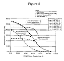
- FIG. 5 is a graph showing the slurry catalyst loading versus bed height when operating in a slumped bed mode and a dispersed bed mode.
- the present invention is applicable to chemical reactions which are carried out in a three-phase slurry reactor.
- a specific example of such reactions is the Fischer-Tropsch synthesis process, and for convenience, the invention will be described by specific reference to the Fischer-Tropsch hydrocarbon synthesis process.
- the reactor for a Fischer-Tropsch synthesis process conducted according to the present invention comprises a vertical vessel for containing a catalyst suspended in a liquid phase through which synthesis gas is bubbled.
- the synthesis gas comprises H 2 and CO in the molar ratio of from about 1:1 to about 3:1.
- the ratio preferably is 2.1:1.
- the catalyst will comprise effective amounts of Co and one or more of Re, Ru, Fe, Ni, Th, Zr, Hf, U, Mg and La on a suitable inorganic support material.
- Those linear hydrocarbon reaction products that are liquids at reaction conditions comprise the slurry liquid in the reactor.
- the Fischer-Tropsch reaction is carried out at temperatures in the range of about 320° F. to 850° F. and pressures in the range of 80 to 600 psi.
- the synthesis gas is injected at or near the bottom of the reactor at a superficial gas velocity sufficient to overcome the settling velocity of catalyst particles.
- the synthesis gas is injected at or near the bottom of the reactor at a superficial velocity sufficient to provide a non-homogeneous slurry having an upper region and a lower region.
- the catalyst concentration in the upper region of the slurry bed will contain less than about 20 wt % of catalyst solids, preferably the solids concentration in the slurry will be less than 10 wt %, and most preferably the solids concentration will be less than 5 wt %.
- FIG. 5 shows two examples of the slumped bed operation where the solids concentration in the upper region of the bed range between about 20 wt % and about 1 wt % catalyst solids.
- the catalyst concentration profile along the reactor height in the slurry bed will depend, of course, not only on the gas velocity but also on the catalyst particle size, particle density, total loading of the catalyst, the height and diameter of the reactor, and the slurry liquid density and viscosity.
- the catalyst particle size refers to the effective catalyst particle diameter.
- the bulk catalyst refers to catalyst particles having an average size greater than or equal to about 10 microns, for example, in the range of about 10 to 150 microns.
- fines is meant particles having a particle size below about 10 microns, for example, in the range of about 0.1 to 10 microns.
- the Fischer-Tropsch is operated in a slumped-bed mode.
- this is achieved by using a reactor without internal downcomers and injecting the synthesis operating gas at or near the bottom of the reactor at a superficial gas velocity sufficient that the catalyst concentration in the upper region of the slurry is less than about 20 wt % solids.
- the slumped-bed operation is achieved using a reactor that is provided with internal downcomers for circulating slurry in the reactor. These downcomers are sized and positioned in the reactor so that under operating conditions the concentration of catalyst solids in the slurry in the upper region of the slurry bed is less than about 20 wt %.
- liquid in the upper region of the slurry containing less than about 20 wt % solids is degassed and passed to a liquid-solids separation device for separation of bulk solids.
- the bulk catalyst particles that are separated from the liquid are returned at or near the bottom of the reactor.
- the liquid separated may be subjected to a second-stage separation step for removal of fines and the liquid product may be sent for further processing, if needed.
- FIG. 1 shows a reactor vessel 10 containing a slurry liquid 11 which has an upper region 12 and a lower region 14 .
- Vessel 10 includes a gas head space 15 and a gas distributor 16 .
- Conduit means is provided for injecting synthesis gas into the slurry liquid for reaction therein.
- Conduit means 18 is provided for removing gaseous products from head space 15 .
- Vessel 10 includes a gas disengaging zone 19 located in region 12 . As shown in FIG. 1 , the gas disengaging zone 19 is in the form of a cup-like top 20 on downcomer 21 .
- Conduit means 22 is provided for removing degassed slurry for transfer to a liquid-solid separation device 23 .
- FIG. 1 shows a reactor vessel 10 containing a slurry liquid 11 which has an upper region 12 and a lower region 14 .
- Vessel 10 includes a gas head space 15 and a gas distributor 16 .
- Conduit means is provided for injecting synthesis gas into the
- separator 23 is shown representing an inclined plate separator other solid liquid separators may be used.
- Conduit means 25 is provided for returning bulk catalyst particles to the bottom region of the slurry liquid.
- Conduit 26 is provided for removing slurry liquid for the separation of catalyst fines in a second separation stage and for other processing as required.
- vessel 10 may include downcomers that do not span the entire length of slurry bed 11 and are located in the lower region 14 for circulating catalyst at the bottom of the reactor.
- Downcomer 27 shown in FIG. 1 , represents one such downcomer.
- vessel 10 does not require internal filters for removing product, internal filters (not shown) may be used.
- a hydroclone 29 is used to separate the solids from the liquid.
- degassed slurry is transferred via conduit 22 to hydroclone 29 , which separates the slurry stream into an overflow stream and a catalyst-containing underflow stream.
- the slurry liquid overflow stream is removed via conduit 26 for the separation of catalyst fines in a second separation stage and for other processing as required.
- the bulk catalyst is returned to the bottom region of the slurry liquid via conduit 25 .
- degassed slurry is withdrawn from the main vertical section 30 of an external downcomer via line 31 for separation in a liquid-solid separation device 32 , such as an inclined plate separator or a hydroclone. Liquid is removed via line 33 for fines separation and any additional processing while bulk catalyst is returned to the slurry reactor via line 34 .
- a liquid-solid separation device 32 such as an inclined plate separator or a hydroclone.
- the slurry can be withdrawn, as shown in FIG. 4 , from the main vertical section 21 of an internal downcomer for separation and further treatment similar to that shown in FIG. 3 .
- the liquids-solids separation is simplified.
- the present invention makes it possible to eliminate the use of filters to separate solids from the liquid removed from the slurry bubble column. This is done by reducing the solids concentration in the slurry sent to liquid-solids separation.
- a computer model of the slurry reactor system was used to illustrate the solid catalyst distribution in a slurry bed as a function of slurry bed height.
- the model couples reaction kinetics with slurry bubble hydrodynamics.
- the model was provided with the feed composition, reaction temperature and pressure, the catalyst type, density and particle size distribution, and the reactor geometry.
- the catalyst concentration for both a slumped bed operation and a dispersed bed operation was determined and shown graphically in FIG. 5 .
- operating in a slumped bed mode is capable of achieving much less than about 20 wt % catalyst concentration as the reactor height increases.
- the same effect can also be achieved by decreasing the reactor downcomer height.
- the slurry catalyst concentration in a dispersed bed operation starts to decrease rapidly once the slurry level is above the downcomer height, which in this example is 66 feet.
Landscapes
- Chemical & Material Sciences (AREA)
- Organic Chemistry (AREA)
- Chemical Kinetics & Catalysis (AREA)
- Engineering & Computer Science (AREA)
- Oil, Petroleum & Natural Gas (AREA)
- Combustion & Propulsion (AREA)
- General Chemical & Material Sciences (AREA)
- Devices And Processes Conducted In The Presence Of Fluids And Solid Particles (AREA)
Abstract
Description
Claims (6)
Priority Applications (5)
| Application Number | Priority Date | Filing Date | Title |
|---|---|---|---|
| US12/592,168 US8119014B2 (en) | 2008-12-23 | 2009-11-20 | Systems and methods to remove liquid product and fines from a slurry reactor |
| EP09796162A EP2379675A1 (en) | 2008-12-23 | 2009-12-23 | Systems and methods to remove liquid product and fines from a slurry reactor |
| PCT/US2009/006708 WO2010074762A1 (en) | 2008-12-23 | 2009-12-23 | Systems and methods to remove liquid product and fines from a slurry reactor |
| AU2009330672A AU2009330672B2 (en) | 2008-12-23 | 2009-12-23 | Systems and methods to remove liquid product and fines from a slurry reactor |
| CN200980154987.XA CN102292416B (en) | 2008-12-23 | 2009-12-23 | System and method for removing liquid product and fines from a slurry reactor |
Applications Claiming Priority (2)
| Application Number | Priority Date | Filing Date | Title |
|---|---|---|---|
| US20352508P | 2008-12-23 | 2008-12-23 | |
| US12/592,168 US8119014B2 (en) | 2008-12-23 | 2009-11-20 | Systems and methods to remove liquid product and fines from a slurry reactor |
Publications (2)
| Publication Number | Publication Date |
|---|---|
| US20100160460A1 US20100160460A1 (en) | 2010-06-24 |
| US8119014B2 true US8119014B2 (en) | 2012-02-21 |
Family
ID=42267045
Family Applications (1)
| Application Number | Title | Priority Date | Filing Date |
|---|---|---|---|
| US12/592,168 Active 2030-02-11 US8119014B2 (en) | 2008-12-23 | 2009-11-20 | Systems and methods to remove liquid product and fines from a slurry reactor |
Country Status (5)
| Country | Link |
|---|---|
| US (1) | US8119014B2 (en) |
| EP (1) | EP2379675A1 (en) |
| CN (1) | CN102292416B (en) |
| AU (1) | AU2009330672B2 (en) |
| WO (1) | WO2010074762A1 (en) |
Cited By (1)
| Publication number | Priority date | Publication date | Assignee | Title |
|---|---|---|---|---|
| US20130084223A1 (en) * | 2010-08-16 | 2013-04-04 | Emerging Fuels Technology, Inc. | Three phase reactor |
Families Citing this family (13)
| Publication number | Priority date | Publication date | Assignee | Title |
|---|---|---|---|---|
| US8389585B2 (en) * | 2009-02-13 | 2013-03-05 | Exxonmobil Research And Engineering Company | Slurry reactor fines segregation and removal |
| CN102773050B (en) * | 2012-08-14 | 2014-05-28 | 迈瑞尔实验设备(上海)有限公司 | Structure and method for solid-liquid separation and circulation |
| CN103977747B (en) * | 2013-02-08 | 2018-01-30 | 上海碧科清洁能源技术有限公司 | Paste state bed reactor and the method that slurry reactor is carried out with the paste state bed reactor |
| WO2014121722A1 (en) * | 2013-02-08 | 2014-08-14 | Shanghai Bi Ke Clean Energy Technology Co., Ltd. | A slurry-bed reactor and method of use |
| CN103170284B (en) * | 2013-04-03 | 2016-02-17 | 神华集团有限责任公司 | Fischer-Tropsch synthesis system and process of high-temperature and high-pressure slurry bed reactor |
| CN103263790A (en) * | 2013-04-27 | 2013-08-28 | 北京市环境卫生设计科学研究所 | Three-phase separation method for household refuse and ventilation blast cap |
| CN104549064A (en) * | 2013-10-28 | 2015-04-29 | 中国石油化工股份有限公司 | Slurry bed reactor and applications thereof |
| BR112018003216B1 (en) * | 2015-08-19 | 2022-04-19 | Sasol Technology Proprietary Limited | Method for starting a column reactor with mud bubbles |
| EP3235560A1 (en) * | 2016-04-22 | 2017-10-25 | Evonik Röhm GmbH | Method for performing a heterogeneously catalysed reaction |
| CN107720959B (en) * | 2017-11-23 | 2020-08-04 | 青岛理工大学 | A gas-liquid-solid three-phase separator |
| CN111036150B (en) * | 2019-12-02 | 2023-07-25 | 河南金鹏化工有限公司 | Thiodicarb alcohol washing continuous production process and device |
| CN111905659B (en) * | 2020-08-24 | 2022-04-19 | 中国科学院青岛生物能源与过程研究所 | Method and device for extracting cleaning liquid from slurry bed |
| EP4371660A1 (en) * | 2022-11-21 | 2024-05-22 | Röhm GmbH | Method for preparing a catalyst for the production of methyl methacrylate using clarification |
Citations (22)
| Publication number | Priority date | Publication date | Assignee | Title |
|---|---|---|---|---|
| US4230556A (en) | 1978-12-15 | 1980-10-28 | Gulf Oil Corporation | Integrated coal liquefaction-gasification process |
| US5157054A (en) | 1990-04-04 | 1992-10-20 | Exxon Research And Engineering Company | Catalyst fluidization improvements (C-2546) |
| US5776988A (en) | 1995-11-10 | 1998-07-07 | Institut Francais Du Petrole | Process for converting synthesis gas into hydrocarbons |
| US5866621A (en) | 1997-05-06 | 1999-02-02 | Exxon Research And Engineering Company | Gas and solids reducing slurry downcomer |
| US5900159A (en) | 1996-02-29 | 1999-05-04 | Shell Oil Company | Method for separating liquid from a slurry |
| US6068760A (en) | 1997-08-08 | 2000-05-30 | Rentech, Inc. | Catalyst/wax separation device for slurry Fischer-Tropsch reactor |
| US6096789A (en) | 1998-04-23 | 2000-08-01 | Agip Petroli S.P.A. | Process for the preparation of hydrocarbons from synthesis gas |
| US6331196B1 (en) | 2000-06-01 | 2001-12-18 | Negev Tornado Ltd. | Low turbulence co-current cyclone separator |
| US6420497B1 (en) | 1999-12-03 | 2002-07-16 | Phillips Petroleum Company | Solids concentration in slurry polymerization |
| US6462098B1 (en) | 1999-02-05 | 2002-10-08 | Sasol Technology (Proprietary) Limited | Process for producing liquid and, optionally, gaseous products from gaseous reactants |
| US20040050806A1 (en) | 2002-09-13 | 2004-03-18 | Conoco Inc. | Solid-liquid separation system |
| US6716887B2 (en) | 2000-06-06 | 2004-04-06 | Bp Exploration Operating Company Limited | Fischer-tropsch process |
| US6730221B2 (en) | 2001-05-29 | 2004-05-04 | Rentech, Inc. | Dynamic settler |
| US20040250973A1 (en) | 2000-08-17 | 2004-12-16 | Johns Philip Kenneth | Kaolin products and their production |
| US20050004238A1 (en) | 2003-06-25 | 2005-01-06 | Eni S.P.A. | Process for the production in continuous of hydrocarbons from synthesis gas in slurry reactors and for the separation of the liquid phase produced from the solid phase |
| US20050109715A1 (en) | 2003-11-24 | 2005-05-26 | Texaco Inc. | Method and apparatus for separating solids from a slurry |
| US6903141B2 (en) | 1999-09-21 | 2005-06-07 | Hydrocarbon Technologies, Inc. | Slurry-phase skeletal iron catalyst process for synthesis gas conversion to hydrocarbons |
| US7078439B2 (en) | 2001-12-28 | 2006-07-18 | Conocophillips Company | Systems and methods for catalyst/hydrocarbon product separation |
| US7111738B2 (en) | 2002-07-22 | 2006-09-26 | Mba Polymers, Inc. | Technique for enhancing the effectiveness of slurried dense media separations |
| US20070014703A1 (en) | 2001-06-25 | 2007-01-18 | Jean-Mare Schweitzer | Apparatus and process for optimising the circulation of a suspension in a facility comprising a three-phase reactor |
| US20070039852A1 (en) | 2005-08-16 | 2007-02-22 | Khakdaman Hamid R | Continuous catalyst / wax separation method |
| US20070161715A1 (en) | 2005-12-28 | 2007-07-12 | Long David C | Filtration system for slurry hydrocarbon synthesis process using both small and large pore filter elements |
Family Cites Families (1)
| Publication number | Priority date | Publication date | Assignee | Title |
|---|---|---|---|---|
| SG82693A1 (en) * | 1999-09-03 | 2001-08-21 | Sumitomo Chemical Co | Fluidized bed reactor for gas phase olefin polymerization, process for polymerizing olefin and process for producing olefin polymer |
-
2009
- 2009-11-20 US US12/592,168 patent/US8119014B2/en active Active
- 2009-12-23 EP EP09796162A patent/EP2379675A1/en not_active Withdrawn
- 2009-12-23 WO PCT/US2009/006708 patent/WO2010074762A1/en not_active Ceased
- 2009-12-23 CN CN200980154987.XA patent/CN102292416B/en not_active Expired - Fee Related
- 2009-12-23 AU AU2009330672A patent/AU2009330672B2/en not_active Ceased
Patent Citations (23)
| Publication number | Priority date | Publication date | Assignee | Title |
|---|---|---|---|---|
| US4230556A (en) | 1978-12-15 | 1980-10-28 | Gulf Oil Corporation | Integrated coal liquefaction-gasification process |
| US5157054A (en) | 1990-04-04 | 1992-10-20 | Exxon Research And Engineering Company | Catalyst fluidization improvements (C-2546) |
| US5776988A (en) | 1995-11-10 | 1998-07-07 | Institut Francais Du Petrole | Process for converting synthesis gas into hydrocarbons |
| US5900159A (en) | 1996-02-29 | 1999-05-04 | Shell Oil Company | Method for separating liquid from a slurry |
| US5866621A (en) | 1997-05-06 | 1999-02-02 | Exxon Research And Engineering Company | Gas and solids reducing slurry downcomer |
| US6068760A (en) | 1997-08-08 | 2000-05-30 | Rentech, Inc. | Catalyst/wax separation device for slurry Fischer-Tropsch reactor |
| US6096789A (en) | 1998-04-23 | 2000-08-01 | Agip Petroli S.P.A. | Process for the preparation of hydrocarbons from synthesis gas |
| US6462098B1 (en) | 1999-02-05 | 2002-10-08 | Sasol Technology (Proprietary) Limited | Process for producing liquid and, optionally, gaseous products from gaseous reactants |
| US6903141B2 (en) | 1999-09-21 | 2005-06-07 | Hydrocarbon Technologies, Inc. | Slurry-phase skeletal iron catalyst process for synthesis gas conversion to hydrocarbons |
| US6420497B1 (en) | 1999-12-03 | 2002-07-16 | Phillips Petroleum Company | Solids concentration in slurry polymerization |
| US6331196B1 (en) | 2000-06-01 | 2001-12-18 | Negev Tornado Ltd. | Low turbulence co-current cyclone separator |
| US6716887B2 (en) | 2000-06-06 | 2004-04-06 | Bp Exploration Operating Company Limited | Fischer-tropsch process |
| US20040250973A1 (en) | 2000-08-17 | 2004-12-16 | Johns Philip Kenneth | Kaolin products and their production |
| US6730221B2 (en) | 2001-05-29 | 2004-05-04 | Rentech, Inc. | Dynamic settler |
| US20070014703A1 (en) | 2001-06-25 | 2007-01-18 | Jean-Mare Schweitzer | Apparatus and process for optimising the circulation of a suspension in a facility comprising a three-phase reactor |
| US7078439B2 (en) | 2001-12-28 | 2006-07-18 | Conocophillips Company | Systems and methods for catalyst/hydrocarbon product separation |
| US7111738B2 (en) | 2002-07-22 | 2006-09-26 | Mba Polymers, Inc. | Technique for enhancing the effectiveness of slurried dense media separations |
| US20040050806A1 (en) | 2002-09-13 | 2004-03-18 | Conoco Inc. | Solid-liquid separation system |
| US6833078B2 (en) | 2002-09-13 | 2004-12-21 | Conocophillips Company | Solid-liquid separation system |
| US20050004238A1 (en) | 2003-06-25 | 2005-01-06 | Eni S.P.A. | Process for the production in continuous of hydrocarbons from synthesis gas in slurry reactors and for the separation of the liquid phase produced from the solid phase |
| US20050109715A1 (en) | 2003-11-24 | 2005-05-26 | Texaco Inc. | Method and apparatus for separating solids from a slurry |
| US20070039852A1 (en) | 2005-08-16 | 2007-02-22 | Khakdaman Hamid R | Continuous catalyst / wax separation method |
| US20070161715A1 (en) | 2005-12-28 | 2007-07-12 | Long David C | Filtration system for slurry hydrocarbon synthesis process using both small and large pore filter elements |
Non-Patent Citations (1)
| Title |
|---|
| J. K. Neathery, et al., Quarterly Report, "Separation of Fischer-Tropsch Wax Products from Ultrafine Iron Catalyst Particles", Reporting period-Apr. 1, 2005 to Sep. 30, 2005, The University of Kentucky Center for Applied Energy Research, DE-FC26-03NT41965. |
Cited By (2)
| Publication number | Priority date | Publication date | Assignee | Title |
|---|---|---|---|---|
| US20130084223A1 (en) * | 2010-08-16 | 2013-04-04 | Emerging Fuels Technology, Inc. | Three phase reactor |
| US8894939B2 (en) * | 2010-08-16 | 2014-11-25 | Emerging Fuels Technology, Inc. | Three phase reactor |
Also Published As
| Publication number | Publication date |
|---|---|
| AU2009330672B2 (en) | 2014-11-27 |
| AU2009330672A1 (en) | 2011-07-21 |
| US20100160460A1 (en) | 2010-06-24 |
| CN102292416A (en) | 2011-12-21 |
| CN102292416B (en) | 2014-04-16 |
| EP2379675A1 (en) | 2011-10-26 |
| WO2010074762A1 (en) | 2010-07-01 |
Similar Documents
| Publication | Publication Date | Title |
|---|---|---|
| US8119014B2 (en) | Systems and methods to remove liquid product and fines from a slurry reactor | |
| AU664429B2 (en) | Catalytic multi-phase reactor | |
| US5770629A (en) | Slurry hydrocarbon synthesis with external product filtration | |
| AU2003235080B2 (en) | Solid-liquid separation system | |
| US9278891B2 (en) | Apparatus and method for conducting a fischer-tropsch synthesis reaction | |
| JP2000506061A (en) | Method for separating liquid from slurry and method for producing hydrocarbon | |
| US8114915B2 (en) | Method and system for handling slurries of varying liquid rates and solids content | |
| AU720266B2 (en) | Catalyst/wax separation device for slurry fischer-tropsch reactor | |
| US8389585B2 (en) | Slurry reactor fines segregation and removal | |
| US20140286834A1 (en) | Integrated multi-step solid/liquid separation system for fischer-tropsch processes | |
| US10590348B2 (en) | Slurry bubble column reactor for a fischer-tropsch process | |
| EP2379215B1 (en) | Method for fines management in slurry processes |
Legal Events
| Date | Code | Title | Description |
|---|---|---|---|
| AS | Assignment |
Owner name: EXXONMOBIL RESEARCH AND ENGINEERING COMPANY,NEW JE Free format text: ASSIGNMENT OF ASSIGNORS INTEREST;ASSIGNORS:SOTO, JORGE L., MR.;COULALOGLOU, COSTAS A., MR.;SIGNING DATES FROM 20100115 TO 20100125;REEL/FRAME:023949/0889 Owner name: EXXONMOBIL RESEARCH AND ENGINEERING COMPANY, NEW J Free format text: ASSIGNMENT OF ASSIGNORS INTEREST;ASSIGNORS:SOTO, JORGE L., MR.;COULALOGLOU, COSTAS A., MR.;SIGNING DATES FROM 20100115 TO 20100125;REEL/FRAME:023949/0889 |
|
| STCF | Information on status: patent grant |
Free format text: PATENTED CASE |
|
| FPAY | Fee payment |
Year of fee payment: 4 |
|
| MAFP | Maintenance fee payment |
Free format text: PAYMENT OF MAINTENANCE FEE, 8TH YEAR, LARGE ENTITY (ORIGINAL EVENT CODE: M1552); ENTITY STATUS OF PATENT OWNER: LARGE ENTITY Year of fee payment: 8 |
|
| MAFP | Maintenance fee payment |
Free format text: PAYMENT OF MAINTENANCE FEE, 12TH YEAR, LARGE ENTITY (ORIGINAL EVENT CODE: M1553); ENTITY STATUS OF PATENT OWNER: LARGE ENTITY Year of fee payment: 12 |