US8110325B2 - Substrate treatment method - Google Patents
Substrate treatment method Download PDFInfo
- Publication number
- US8110325B2 US8110325B2 US13/022,811 US201113022811A US8110325B2 US 8110325 B2 US8110325 B2 US 8110325B2 US 201113022811 A US201113022811 A US 201113022811A US 8110325 B2 US8110325 B2 US 8110325B2
- Authority
- US
- United States
- Prior art keywords
- treatment
- treatment process
- resist pattern
- wafer
- substrate
- Prior art date
- Legal status (The legal status is an assumption and is not a legal conclusion. Google has not performed a legal analysis and makes no representation as to the accuracy of the status listed.)
- Expired - Fee Related
Links
Images


Classifications
-
- H10P76/204—
-
- G—PHYSICS
- G03—PHOTOGRAPHY; CINEMATOGRAPHY; ANALOGOUS TECHNIQUES USING WAVES OTHER THAN OPTICAL WAVES; ELECTROGRAPHY; HOLOGRAPHY
- G03F—PHOTOMECHANICAL PRODUCTION OF TEXTURED OR PATTERNED SURFACES, e.g. FOR PRINTING, FOR PROCESSING OF SEMICONDUCTOR DEVICES; MATERIALS THEREFOR; ORIGINALS THEREFOR; APPARATUS SPECIALLY ADAPTED THEREFOR
- G03F1/00—Originals for photomechanical production of textured or patterned surfaces, e.g., masks, photo-masks, reticles; Mask blanks or pellicles therefor; Containers specially adapted therefor; Preparation thereof
- G03F1/60—Substrates
-
- G—PHYSICS
- G03—PHOTOGRAPHY; CINEMATOGRAPHY; ANALOGOUS TECHNIQUES USING WAVES OTHER THAN OPTICAL WAVES; ELECTROGRAPHY; HOLOGRAPHY
- G03F—PHOTOMECHANICAL PRODUCTION OF TEXTURED OR PATTERNED SURFACES, e.g. FOR PRINTING, FOR PROCESSING OF SEMICONDUCTOR DEVICES; MATERIALS THEREFOR; ORIGINALS THEREFOR; APPARATUS SPECIALLY ADAPTED THEREFOR
- G03F7/00—Photomechanical, e.g. photolithographic, production of textured or patterned surfaces, e.g. printing surfaces; Materials therefor, e.g. comprising photoresists; Apparatus specially adapted therefor
- G03F7/0035—Multiple processes, e.g. applying a further resist layer on an already in a previously step, processed pattern or textured surface
-
- H10P72/0458—
-
- H10P74/23—
-
- H10P76/2041—
-
- H10P74/203—
Definitions
- Embodiments described herein relate generally to a substrate treatment method.
- photolithography is used as a patterning technology for forming a circuit pattern on a semiconductor wafer (hereinafter, referred to as a wafer) that is a substrate to be processed.
- a wafer a semiconductor wafer
- photolithography is used by applying a resist liquid on a wafer to form a resist film, irradiating a light, exposing the resist film so as to correspond to the circuit pattern, and developing the exposed resist film.
- LLE lithography-lithography etching
- a first-time patterning process is performed to form a first-time resist pattern and a second-time patterning process is performed to form a second-time resist pattern, such that an etching process is performed by using the first-time and second-time resist patterns as masks.
- a first-time patterning process is performed to form a first-time resist pattern (e.g., a first resist pattern) and then a second-time patterning process is performed to form a second-time resist pattern (e.g., a second resist pattern).
- a treatment condition in the first-time patterning process is required to be controlled or compensated so as to reduce a variation between wafers or in surfaces of the wafers, each of which has a line width (e.g., CD) of the first resist pattern.
- a treatment condition in the second-time patterning process is required to be controlled or compensated so as to reduce a variation between the wafers or in the surfaces of the wafers, each of which has a line width (e.g., CD) of the second resist pattern.
- a line width e.g., CD
- double patterning is performed through a lithography-lithography etching (LLE) such that a variation in line widths of the first-time and second-time resist patterns is reduced between wafers and in surfaces of the wafers upon forming fine resist patterns.
- LLE lithography-lithography etching
- a method of processing a substrate includes a first treatment process for exposing an initial substrate on which a first resist film is formed, heating the exposed initial substrate, and developing the heated initial substrate, thereby forming a first resist pattern; and a second treatment process for forming a second resist film on the initial substrate on which the first resist pattern is formed, exposing the initial substrate on which the second resist film is formed, heating the exposed initial substrate, and developing the heated initial substrate, thereby forming a second resist pattern, wherein, after the second treatment process is performed on the initial substrate, a line width of the second resist pattern formed on the initial substrate is measured, a first treatment condition in the first treatment process is compensated based on a measured value of the line width of the second resist pattern, the first treatment process is performed on one of subsequent substrates in compliance with the compensated first treatment condition, a line width of the first resist pattern formed on the initial substrate is measured, a second treatment condition in the second treatment process is compensated based on a measured value of the line
- FIG. 1 is a schematic perspective view showing a configuration of a substrate treatment system in accordance with Embodiment 1 of the present disclosure.
- FIG. 2 is a schematic horizontal sectional view showing a part of a DEV layer of the substrate treatment system in accordance with Embodiment 1 of the present disclosure.
- FIG. 3 is a schematic lateral view of the substrate treatment system in accordance with Embodiment 1 of the present disclosure.
- FIG. 4 is a perspective view showing a layout of the DEV layer.
- FIG. 5 is a vertical sectional view showing a heating unit and a main arm of the DEV layer.
- FIG. 6 is a vertical sectional view showing a schematic configuration of a line width measuring apparatus.
- FIGS. 7A and 7B are flow charts showing respective processes of a substrate treatment method in accordance with Embodiment 1 of the present disclosure.
- FIGS. 8A to 8J are sectional views showing states of a wafer in the respective processes of the substrate treatment method in accordance with Embodiment 1 of the present disclosure.
- FIGS. 9A to 9D are graphs showing relationships between space widths of first and second resist patterns and first and second temperatures.
- FIG. 10 is a graph showing the sensitivity of a space width with respect to temperature.
- FIGS. 11A and 11B are flow charts showing respective processes of a substrate treatment method in accordance with Embodiment 2 of the present disclosure.
- FIGS. 12A to 12J are sectional views showing states of a wafer in respective processes of a substrate treatment method in accordance with Embodiment 2 of the present disclosure.
- FIGS. 13A to 13D are graphs showing relationships between space widths of first and second resist patterns and first and second dose amounts.
- FIG. 14 is a graph showing the sensitivity of a space width with respect to a dose amount.
- FIG. 1 is a schematic perspective view showing a configuration of a substrate treatment system 100 according to this embodiment.
- FIG. 2 is a schematic horizontal sectional view showing a part of a DEV layer of the substrate treatment system 100 and
- FIG. 3 is a schematic lateral view showing the substrate treatment system 100 .
- the substrate treatment system 100 is configured to perform on a wafer W a coating treatment of a coating film including a photo resist and a developing treatment after an exposing treatment.
- the substrate treatment system 100 may correspond to double patterning or performing a patterning process twice. Also, the substrate treatment system 100 may be disposed in a clean room having an atmosphere of air.
- the substrate treatment system 100 includes a carrier block S 1 , a treatment block S 2 , and an interface block S 3 .
- the carrier block S 1 is configured to take in and out a carrier 20 which accommodates a plurality of wafers W to be processed.
- the treatment block S 2 is configured to perform a coating treatment on the wafer W to form a coating film including a photoresist film that serves as a photosensitive material and a developing treatment to develop a photoresist film that has been exposed through an exposure pattern.
- the substrate treatment system 100 may be used in a state where an exposing apparatus 200 is connected to the interface block S 3 .
- a main body control unit 10 that may control the entire operation of the substrate treatment system 100 is disposed at a lower portion of the carrier block S 1 .
- the main body control unit 10 will be described later in detail.
- a control unit (not shown) is disposed in the exposing apparatus 200 .
- a width direction of the substrate treatment system 100 is in an X-direction
- an arrangement direction of the carrier block S 1 , the treatment block S 2 and the interface block S 3 , which are perpendicular to the X-direction, is in a Y-direction.
- a vertical direction with respect to the X-direction is in a Z-direction.
- a mounting table 21 capable of mounting a plurality of carriers 20 , an opening/closing unit 22 arranged on a front wall from the mounting table 21 , and a transfer arm C for taking out the wafer W from the carrier 20 through the opening/closing unit 22 are disposed.
- the transfer arm C is configured to be extendable, retractable, elevatable, descendible, rotatable around a vertical axis, and movable in an arrangement direction of the carriers 20 .
- a line width measuring apparatus 110 for measuring a line width of a resist pattern on the wafer W is disposed at the carrier block S 1 .
- the treatment block S 2 is enclosed by a housing 24 and connected to the carrier block S 1 .
- the treatment block S 2 includes first and second sub-blocks SB 1 and SB 2 which are made of a plurality of treatment layers that are stacked and arranged in parallel in the Y-direction.
- a second developing treatment unit 12 for performing a second-time developing treatment is arranged on a bottom side, and a first coating treatment unit 11 for performing a first-time coating treatment is arranged over the second developing treatment unit 12 .
- the second developing treatment unit 12 is configured with two developing treatment layers B 1 (e.g., DEV layers) which have the same structure as each other and are stacked in a vertical direction.
- the first coating treatment unit 11 is configured with a bottom anti-reflective coating treatment layer B 2 (e.g., a BCT layer), a resist coating treatment layer B 3 (e.g., a COT layer), and a top anti-reflective coating treatment layer B 4 (e.g., a TCT layer), which are stacked in turn from a bottom side.
- the bottom anti-reflective coating treatment layer B 2 e.g., the BCT layer
- the resist coating treatment layer B 3 is configured to perform a coating treatment of a resist liquid.
- the top anti-reflective coating treatment layer B 4 (e.g., the TCT layer) is configured to perform a coating treatment of a top anti-reflective coating (TARC) film that is formed on a top layer of the resist film.
- the first sub-block SB 1 further includes a first transfer layer M 1 between the second developing treatment unit 12 and the first coating treatment unit 11 , and a second transfer layer M 2 at a lowermost stage.
- a first developing treatment unit 14 for performing a first-time developing treatment is arranged on a bottom side, and a second coating treatment unit 13 for performing a second-time coating treatment is arranged over the first developing treatment unit 14 .
- the first developing treatment unit 14 is configured with two developing treatment layers B 5 (e.g., DEV layers) which have the same structure as each other and are stacked in a vertical direction.
- the DEV layers B 5 have the same structure as those in the DEV layers B 1 .
- the second coating treatment unit 13 is configured with a cleaning/surface treatment layer B 6 (e.g., a C/S layer), a resist coating treatment layer B 7 (e.g., a COT layer), and a top anti-reflective coating treatment layer B 8 (e.g., a TCT layer), which are stacked in turn from a bottom side.
- the cleaning/surface treatment layer B 6 e.g., the C/S layer
- the cleaning/surface treatment layer B 6 is configured to perform a cleaning treatment and/or a surface treatment, e.g., a cure treatment, of a TARC film.
- the cleaning/surface treatment layer B 6 (e.g., the C/S layer) is disposed so as to prevent a coating treatment from being performed while particles are attached to a surface of a TARC film, or a leaching from occurring, when a second-time treatment is performed on the TARC film that is a top film upon performing the first-time coating treatment.
- the resist coating treatment layer B 7 (e.g., the COT layer) is configured to perform a coating treatment using a resist liquid.
- the top anti-reflective coating treatment layer B 8 (e.g., the TCT layer) is configured to perform a coating treatment for an antireflection film that is formed on a top layer of a resist film.
- the second sub-block SB 2 further includes a third transfer layer M 3 between the first developing treatment unit 14 and the second coating treatment unit 13 , and a fourth transfer layer M 4 at a lowermost stage. Also, the respective layers of the first and second sub-blocks SB 1 and SB 2 are partitioned by partition plates (e.g., base bodies).
- partition plates e.g., base bodies
- the treatment block S 2 includes a first transfer rack unit TU 1 at a side of the carrier block 51 .
- the first transfer rack unit TU 1 is configured with a plurality of transfer stages which are stacked in a vertical direction along the treatment layers B 1 to B 4 and the transfer layers M 1 and M 2 .
- the treatment block S 2 includes a second transfer rack unit TU 2 which is provided between the first sub-block SB 1 and the second sub-block SB 2 .
- the second transfer rack unit TU 2 is configured with a multiplicity of transfer stages which are stacked in a vertical direction along the treatment layers B 1 to B 4 and the transfer layers M 1 and M 2 , and the treatment layers B 5 to B 8 and the transfer layers M 3 and M 4 .
- the treatment block S 2 further includes a third transfer rack unit TU 3 at a side of the interface block S 3 .
- the third transfer rack unit TU 3 is configured with a number of transfer stages which are stacked in a vertical direction along the treatment layers B 5 to B 8 and the transfer layers M 3 and M 4 .
- FIG. 4 is a perspective view showing a layout of the DEV layer.
- FIG. 5 is a vertical sectional view showing a heating unit and a main arm of the DEV layer.
- a transfer passage RS 1 is disposed at a center portion of the DEV layer B 1 .
- a main transfer arm A 1 e.g., a main arm
- a developing treatment unit 3 serving as a liquid treatment unit for performing a developing treatment is disposed along the transfer passage RS 1 .
- four rack units U 1 , U 2 , U 3 , and U 4 that are formed by combining a treatment unit for heating and cooling, and an exhaust unit 5 ; and disposing them along the transfer passage RS 1 . Therefore, the developing treatment unit 3 and the rack units U 1 to U 4 are disposed to face each other while having the transfer passage RS 1 therebetween.
- the developing treatment unit 3 includes a housing 30 and a spin chuck 31 , e.g., three spin chucks, serving as a wafer holding support unit is arranged in the housing 30 .
- the spin chuck 31 is configured to be rotatable or movable up and down around a vertical axis by a driving unit that is not shown.
- a cup 33 is disposed around the spin chuck 31 .
- the wafer W is carried in the housing 30 by the main arm A 1 through a transfer hole 37 that is disposed to face the transfer passage RS 1 , thereby being transferred to the spin chuck 31 .
- the transfer hole 37 is capable of being opened and closed by a shutter 38 .
- a developing solution is supplied from a nozzle, which is not shown, to a surface of the wafer W, thereby forming a liquid film of the developing solution on the surface of the wafer W.
- the developing solution on the surface of the wafer W is cleaned by a cleaning solution from a cleaning solution supply device which is not shown, and then the wafer W is rotated and dried, thereby terminating the developing treatment.
- a heat-series treatment unit for performing a pre-treatment and a post-treatment, which are to be performed in the developing unit 3 is stacked in two stages in the respective rack units U 1 to U 4 .
- an exhaust unit 5 is disposed at a bottom portion of the respective rack units U 1 to U 4 .
- a heating treatment unit 4 of heating the wafer W after exposure or drying the same after development, or a cooling unit of controlling the wafer W after the treatment in the heating treatment unit 4 to a predetermined temperature may be included.
- the heating treatment unit 4 is stacked in two stages in the respective rack units U 1 , U 2 , and U 3
- the cooling treatment unit is stacked in two stages in the rack unit U 4 .
- the heating treatment unit 4 includes a housing 40 and a base 41 is disposed in the housing 40 .
- a transfer hole 42 for the wafer W is formed on a portion of the housing 40 , which faces the transfer passage RS 1 .
- a cooling plate 43 for primary heat removal and a hot plate 44 are disposed in the housing 40 .
- the cooling plate 43 is configured to be movable between a cooling position shown in FIG. 5 and a transfer position on the hot plate 44 .
- a reference numeral 45 of FIG. 5 is a plate used for rectification.
- An elevating pin 47 transfers the wafer W to the cooling plate 43 .
- an elevating pin 48 transfers the wafer W to the hot plate 44 and between the cooling plate 43 and the hot plate 44 .
- cooling unit that constitutes the rack unit U 4
- an apparatus having a housing with a cooling plate of a water cooling type therein and a transfer hole that is opened toward the transfer passage RS 1 may be used as the cooling treatment unit.
- an exhaust unit 5 in the housing 50 , includes a suction hole 51 that is opened toward the transfer passage RS 1 and an exhaust pipe 54 that sucks and exhausts the inside of an exhaust room 53 in the housing 50 .
- the exhaust unit 5 exhausts the inside of the exhaust room 53 to create negative pressure, thereby introducing gas in the transfer passage RS 1 and removing particles contained therein.
- the main arm A 1 is configured to transfer the wafer W among the treatment units in the rack units U 1 to U 4 , the developing treatment unit 3 , a transfer stage of the first transfer rack unit TU 1 , and a transfer stage of the second transfer rack unit TU 2 .
- the main arm A 1 includes, for example, two arm bodies 61 and 62 for supporting a circumference region on a back surface of the wafer W.
- the arm bodies 61 and 62 are configured to be extended and retracted, independently, on a transfer base 63 .
- the arm bodies 61 and 62 are configured to be extended into and retracted from the housing 30 of the developing treatment unit 3 through the transfer hole 37 .
- the transfer base 63 is disposed on an elevating base 64 so as to be capable of rotating around a vertical axis of the same.
- the elevating base 64 is configured to be elevated along an elevating guide rail 67 .
- a guide rail 65 is horizontally disposed on the front sides of the four exhaust units 5 of the rack units U 1 to U 4 .
- the main arm A 1 is configured to move in a horizontal direction along the guide rail 65 through the elevating guide rail 67 .
- a hole 66 is formed on a position of the guide rail 65 , which corresponds to the suction hole 51 . Exhaust of the transfer passage RS 1 is performed through the hole 66 .
- a lower portion of the elevating guide rail 67 reaches the inside of the exhaust unit 5 beyond a lower portion of the guide rail 65 , thereby being suspended on a drive belt 55 for moving the elevating guide rail 67 along the guide rail 65 .
- the DEV layer B 5 is configured to be the same as the DEV layer B 1 and transfers the wafer W through a main arm A 5 that is configured to be the same as the main arm A 1 .
- the BCT layer B 2 , the COT layers B 3 and B 7 , and the TCT layers B 4 and B 8 employ a coating unit instead of the developing treatment unit 3 of the DEV layer B 1 .
- the coating unit is configured to apply a chemical solution for forming an antireflection film or a chemical solution (e.g., a resist liquid) for forming a resist film.
- a basic structure of the coating unit is nearly the same as that in the developing treatment unit 3 .
- the coating unit drops the chemical solution for coating at the center of the wafer W while the spin chuck rotates, and spreads the dropped chemical solution through centrifugal force, thereby forming a coating film.
- the treatment layers B 2 , B 3 , B 4 , B 7 , and B 8 of such coating lineages are partially different from the DEV layer B 1 in units which constitute the rack units U 1 to U 4 . That is, apart from including a heating unit and a cooling unit which are the same as those in the rack units U 1 to U 4 of the DEV layer B 1 , a circumference exposing unit for exposing a circumference of the wafer W is disposed in any one of the treatment layers.
- a unit for performing a hydrophobic treatment on the wafer W is included in the rack units U 1 to U 4 of the COT layer B 3 and B 7 .
- main arms A 2 , A 3 , A 4 , A 7 , and A 8 having the same configurations as the main arm A 1 are disposed such that the wafer W is transferred through these arms.
- a cleaning/surface treatment layer B 6 (e.g., a C/S layer) employs a cleaning unit instead of the developing treatment unit 3 of the DEV layer B 1 .
- a basic structure of the cleaning unit has a structure in which a cup is disposed around the spin chuck, similar to the developing treatment unit 3 .
- the cleaning unit drops de-ionized water or a chemical solution for cleaning at the center of the wafer W while the spin chuck spins and spreads the dropped water or solution through centrifugal force, thereby cleaning a surface of the wafer W.
- the cleaning/surface treatment layer B 6 (e.g., the C/S layer) is partially different from the DEV layer B 1 in units that constitute the rack units U 1 to U 4 . That is, apart from including a heating unit and a cooling unit which are the same as those in the rack units U 1 to U 4 of the DEV layer B 1 , a curing unit that is not shown is disposed.
- the curing unit irradiates ultraviolet light to the wafer W, thereby performing a curing treatment on an uppermost layer of the wafer W.
- the wafer W is transferred by the main arm A 6 which has the same structure as that in the main arm A 1 .
- the first transfer layer M 1 is disposed between the DEV layer B 1 at an upper side of the first sub-block SB 1 and the BCT layer B 2 thereof.
- the first transfer layer M 1 is configured to transfer the wafer W from the first transfer rack unit TU 1 adjacent to the carrier block S 1 to the second transfer rack unit TU 2 , which is arranged in a middle position, by moving straight to the same.
- the first transfer layer M 1 includes a shuttle arm 7 .
- the second transfer layer M 2 is disposed on a lowermost stage of the first sub-block SB 1 . Besides transferring the wafer W from the second transfer rack unit TU 2 to the first transfer rack unit TU 1 by moving straight to the same, the second transfer layer M 2 is configured to be the same as the first transfer layer M 1 .
- the third transfer layer M 3 is disposed between the DEV layer B 5 on an upper side of the second sub-block SB 2 and the C/S layer B 6 thereof. Besides transferring the wafer W from the second transfer rack unit TU 2 to the third transfer rack unit TU 3 , which is adjacent to the interface bock S 3 , by moving straight to the same, the third transfer layer M 3 is configured to be the same as the first transfer layer M 1 .
- the fourth transfer layer M 4 is disposed on a lowermost stage of the second sub-block SB 2 . Besides transferring the wafer W from the third transfer rack unit TU 3 to the second transfer rack unit TU 2 , the fourth transfer layer M 4 is configured to be the same as the first transfer layer M 1 .
- a region in proximity with the carrier block 51 is configured as a first wafer transfer region RS 2 .
- the first transfer rack unit TU 1 is disposed in the first wafer transfer region RS 2 .
- a transfer arm D 1 serving as an elevating transfer device is disposed so as to transfer the wafer W to the first transfer rack unit TU 1 .
- the first transfer rack unit TU 1 includes a transfer stage TRSB at a position corresponding to the second transfer layer M 2 , transfer stages TRS 1 at positions corresponding to the respective DEV layers B 1 , and a transfer stage TRSA at a position corresponding to the first transfer layer M 1 . Also, the first transfer rack unit TU 1 includes two transfer stages TRS 2 at positions corresponding to the BCT layer B 2 , two transfer stages TRS 3 at positions corresponding to the COT layer B 3 , and two transfer stages TRS 4 at positions corresponding to the TCT layer B 4 .
- a transfer arm C is configured to access to the transfer stage TRS 2 corresponding to the BCT layer B 2 from the transfer stage TRSB corresponding to the second transfer layer M 2 which is arranged at the lowermost stage of the first transfer rack unit TU 1 . Also, the transfer arm D 1 is configured to access from the lowermost stage TRSB to the uppermost stage TRS 4 corresponding to the TCT layer B 4 .
- the shuttle arm 7 is configured to access the transfer stages TRSA and TRSB which correspond to the first and second transfer layers M 1 and M 2 , respectively.
- the main arms A 1 to A 4 of the respective treatment layers are configured to access the transfer stages TRS 1 to TRS 4 which correspond to the DEV layer B 1 , the BCT layer B 2 , the COT layer B 3 , and the TCT layer B 4 , respectively.
- a second wafer transfer region RS 3 between the transfer passage RS 1 of the treatment layers B 1 to B 4 of the first sub-block SB 1 and the transfer passage RS 1 of the treatment layers B 5 to B 8 of the second sub-block SB 2 .
- a second transfer rack unit TU 2 is disposed in the second wafer transfer region RS 3 .
- a transfer arm D 2 serving as an elevating transfer device is disposed so as to transfer the wafer W to the second transfer rack unit TU 2 .
- the second transfer rack unit TU 2 includes a transfer stage TRSD at a position corresponding to the fourth transfer layer M 4 , two transfer stages TRS 5 at positions corresponding to the DEV layers B 5 , and a transfer stage TRSC at position corresponding to the third transfer layer M 3 . Also, the second transfer rack unit TU 2 includes two transfer stages TRS 6 at positions corresponding to the C/S layer B 6 , two transfer stages TRS 7 at positions corresponding to the COT layer B 7 , and two transfer stages at positions corresponding to the TCT layer B 8 .
- the transfer arm D 2 is configured to access from the lowermost transfer stage TRSD to the uppermost transfer stage TRS 8 corresponding to the TCT layer B 8 .
- the shuttle arm 7 is configured to access the transfer stages TRSC and TRSD corresponding to the third and fourth transfer layers M 3 and M 4 .
- the main arms A 5 to A 8 of the respective treatment layers are configured to access the transfer stages TRS 5 to TRS 8 which correspond to the DEV layer B 5 , the C/S layer B 6 , the COT layer B 7 , and the TCT layer B 8 , respectively.
- a region in proximity with the interface block S 3 is configured as a third wafer transfer region RS 4 .
- the third transfer rack unit TU 3 is disposed in the third wafer transfer region RS 4 .
- the third transfer rack unit TU 3 includes a transfer stage TRSF at a position corresponding to the fourth transfer layer M 4 , two transfer stages TRS 9 at positions corresponding to the DEV layers B 5 , and a transfer stage TRSE at a position corresponding to the third transfer layer M 3 .
- the shuttle arm 7 is configured to access the transfer stages TRSE and TRSF which correspond to the third and fourth transfer layers M 3 and M 4 , respectively. Also, the main arm A 5 is configured to access the transfer stage TRS 9 corresponding to the DEV layer B 5 .
- the transfer stages TRS 1 to TRS 9 and TRSA to TRSF have the same structure, in which, for example, a housing of a rectangular parallelepiped shape is provided, a stage for mounting the wafer W is interposed in the corresponding housing, and a pin capable of being protruded and depressed on the corresponding stage is disposed. Also, these transfer stages include a device for controlling a temperature of the wafer W to a predetermined temperature.
- two transfer stages are disposed on the respective treatment layers B 2 to B 4 and B 6 to B 8 and one transfer stage is disposed on the DEV layers B 1 and B 5 and the transfer layers M 1 to M 4 , but it is not limited thereto. Therefore, the number of transfer stages on each treatment layer may be appropriately decided depending upon a scheduled transfer sequence.
- the interface block S 3 includes a buffer unit 9 so as to temporarily wait for a plurality of the wafers W upon being carried in and out from the exposing apparatus 200 .
- the buffer unit 9 includes a first carry-in buffer cassette (Bu IN 1 ) 91 , a first carry-out buffer cassette (Bu OUT 1 ) 92 , a second carry-in buffer cassette (Bu IN 2 ) 93 , and a second carry-out buffer cassette (Bu OUT 2 ) 94 .
- the first carry-in buffer cassette (Bu IN 1 ) 91 is configured to receive the wafer W that is carried in the exposing apparatus 200 when a first-time exposing treatment is performed.
- the first carry-out buffer cassette (Bu OUT 1 ) 92 is configured to receive the wafer W that is discharged from the exposing apparatus 200 after the first-time exposing treatment is completed.
- the second carry-in buffer cassette (Bu N 2 ) 93 is configured to receive the wafer W that is carried in the exposing apparatus 200 when a second-time exposing treatment is performed.
- the second carry-out buffer cassette (Bu OUT 2 ) 94 is configured to receive the wafer W that is discharged from the exposing apparatus 200 after the second-time exposing treatment is completed.
- these cassettes are disposed from the top of the buffer 9 in the order of the second carry-in buffer cassette (Bu IN 2 ) 93 , the first carry-in buffer cassette (Bu IN 1 ) 91 , the first carry-out buffer cassette (Bu OUT 1 ) 92 , and the second carry-out buffer cassette (Bu OUT 2 ) 94 .
- a carry-in interface arm E 1 and a carry-out interface arm E 2 are disposed between the buffer unit 9 and the treatment block S 2 .
- the carry-in interface arm E 1 is configured to carry the wafer W in the carry-in buffer cassette 91 or 93 after a coating treatment.
- the carry-out interface arm E 2 is configured to carry out the wafer W from the carry-out buffer cassette 92 or 94 .
- the interface arms E 1 and E 2 are configured to access the transfer stages TRS 9 , TRSE, and TRSF of the third transfer rack unit TU 3 . Therefore, the wafer W is transferred first to the transfer stage TRSE by the shuttle arm 7 of the third transfer layer M 3 and then carried in the carry-in buffer cassette 91 or 93 by the carry-in interface arm E 1 . Also, when the wafer W that is carried out from the carry-out buffer cassette 92 or 94 is returned, it is transferred first to the transfer stage TRS 9 or TRSF by the carry-out interface arm E 2 .
- a first-time exposure interface arm E 3 and a second-time exposure interface arm E 4 are disposed between the buffer unit 9 and the exposing apparatus 200 .
- the first-time exposure interface arm E 3 is configured to transfer the wafer W between the buffer unit 9 and the exposing apparatus 200 for a first-time exposing treatment.
- the second-time exposure interface arm E 4 is configured to transfer the wafer W between the buffer unit 9 and the exposing apparatus 200 for a second-time exposing treatment.
- FIG. 6 is a vertical sectional view showing a schematic configuration of the line width measuring apparatus 110 .
- the line width measuring apparatus 110 includes, for example, a mounting table 111 for mounting the wafer W in a horizontal direction and an optical surface topography measuring arrangement 112 .
- the mounting table 111 is made of, for example, an X-Y stage, and configured to be movable in a 2-dimensional transverse direction.
- the optical surface topography measuring arrangement 112 includes, for example, a light irradiation unit 113 , a light detection unit 114 , and a calculation unit 115 .
- the light irradiation unit 113 is configured to irradiate light onto the wafer W from an inclined direction.
- the light detection unit 114 is configured to detect the light that is irradiated from the light irradiation unit 113 and then reflected from the wafer W.
- the calculation unit 115 is configured to calculate a line width CD of a resist pattern on the wafer W based on information related to the detected light from the light detection unit 114 .
- the line width measuring apparatus 110 is configured to measure the line width of the resist pattern by using, for example, a Scatterometry technique.
- the calculation unit 15 may collate a light intensity distribution, which is detected by the light detection unit 114 , on the surface of the wafer W with a virtual light intensity distribution that is stored in advance. As such, a line width CD of a resist pattern corresponding to the collated virtual light intensity distribution is calculated to be measured.
- the line width measuring apparatus 110 may measure line widths at a plurality of measurement points on a surface of the wafer W by moving the wafer W in a relative horizontal direction with respect to the light irradiation unit 113 and the light detection unit 114 .
- a first-time patterning process is performed on each wafer W of a wafer group consisting of the plurality of wafers W by changing the heating temperature (e.g., a first temperature T 1 ) of the heating treatment with respect to each wafer W through the heating treatment unit 4 , thereby forming a first-time resist pattern P 1 (e.g., a first resist pattern).
- a second-time patterning process is performed on each wafer W that have been subject to the first-time patterning process, thereby forming a second-time resist pattern P 2 (e.g., a second resist pattern).
- line widths CD 1 and CD 2 of the first and second resist patterns P 1 and P 2 are measured by using the line width measuring apparatus 110 .
- first data (e.g., a sensitivity ST 12 to be described later) is prepared, which represents a relationship between the first temperature T 1 and the line width CD 2 of the second resist pattern P 2 .
- a wafer treatment which is performed in a coating/developing treatment system 1 having the above-described configuration, may be controlled by the main body control unit 10 shown in FIG. 1 .
- the main body control unit 10 is also configured to control measuring a line width of a resist pattern on the wafer W through the line width measuring apparatus 110 .
- the main body control unit 10 is configured with, for example, a general purpose computer having a central processing unit (CPU), a memory and the like, and to execute a program stored therein, thereby controlling the wafer treatment and the measurement of a line width.
- the program of the main body control unit 10 may be installed through a computer-readable storage medium.
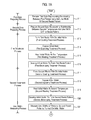
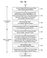
- FIGS. 7A and 7B are flow charts showing respective processes of the substrate treatment method according to this embodiment.
- FIGS. 8A through 8J are sectional views showing states of a wafer in the respective processes of the substrate treatment method according to this embodiment.
- FIGS. 9A through 9D are graphs showing relationships between space widths of first and second resist patterns and first and second temperatures.
- FIG. 10 is a graph showing the sensitivity of a space width with respect to temperature.
- the substrate treatment method includes a first data preparing process (Step S 11 ), a second data preparing process (Step S 12 ), a first treatment process (Step S 13 to Step S 16 ), a second treatment process (Step S 17 to Step S 20 ), a line width measuring process (Step S 21 ), a first treatment process (Step S 22 to Step S 25 ), and a second treatment process (Step S 26 to Step S 29 ).
- the first treatment process (Step S 13 to S 16 ) and the second treatment process (Step S 17 to S 20 ) perform a first treatment process and a second treatment process on an initial wafer W.
- the first treatment process (Step S 13 to Step S 16 ) includes a first coating treatment process (Step S 13 ), a first exposing treatment process (Step S 14 ), a first heating treatment process (Step S 15 ), and a first developing treatment process (Step S 16 ).
- the second treatment process (Step S 17 to Step S 20 ) includes a second coating treatment process (Step S 17 ), a second exposing treatment process (Step S 18 ), a second heating treatment process (Step S 19 ), and a second developing treatment process (Step S 20 ).
- the first treatment process (Step S 22 to Step S 25 ) and the second treatment process (Step S 26 to Step S 29 ) perform a first treatment process and a second treatment process on a subsequent wafer W.
- the first treatment process (Step S 22 to Step S 25 ) includes a first coating treatment process (Step S 22 ), a first exposing treatment process (Step S 23 ), a first heating treatment process (Step S 24 ), and a first developing treatment process (Step S 25 ).
- the second treatment process includes a second coating treatment process (Step S 26 ), a second exposing treatment process (Step S 27 ), a second heating treatment process (Step S 28 ), and a second developing treatment process (Step S 29 ).
- first data preparing process (Step S 11 ) is performed.
- first data is prepared, which represents a relationship between a first temperature T 1 and a space width SP 2 ′ of a second resist pattern P 2 .
- the first coating treatment process (Step S 13 ) and the first exposing treatment process (Step S 14 ), which will be described later, are performed on each wafer W of a wafer group consisting of plurality of wafers W comprising the initial wafer and subsequent wafers, and then the first heating treatment process (Step S 15 ) to be described later is performed with the first temperature T 1 changed on each wafer W.
- the first developing treatment process (Step S 16 ) through the second developing treatment process (Step S 20 ) are performed, thereby forming a first resist pattern P 1 and the second resist pattern P 2 on the initial wafer W as shown in FIGS. 8A through 8J .
- the space width SP 2 ′ of the second resist pattern P 2 formed on the initial wafer W is measured by using the line width measuring apparatus 110 .
- the first data (corresponding to ST 12 to be described later) is prepared, which represents the relationship between the first temperature T 1 and the space width SP 2 ′ of the second resist pattern P 2 .
- a space width SP 1 ′ of the first resist pattern P 1 as formed is measured by using the line width measuring apparatus 110 .
- third data (corresponding to ST 11 to be described later) is also prepared, which represents a relationship between the first temperature T 1 and the space width SP 1 ′ of the first resist pattern P 1 .
- the space width SP 1 ′ of the first resist pattern P 1 and the space width SP 2 ′ of the second resist pattern P 2 may correspond to line widths of resist patterns according to the present disclosure.
- Step S 12 second data is prepared, which represents a relationship between a second temperature T 2 and the space width SP 1 ′ of the first resist pattern P 1 .
- the first coating treatment process (Step S 13 ) through the second exposing treatment process (Step S 18 ), which will be described later, are performed on each wafer W of the wafer group consisting of the plurality of wafers W, and then the second heating treatment process (Step S 19 ) to be described later is performed with the second temperature T 2 changed on each wafer W.
- the second developing treatment process (Step S 20 ) to be described later is performed to form the first resist pattern P 1 and the second resist pattern P 2 on the initial wafer W.
- the space width SP 1 ′ of the first resist pattern P 1 as formed is measured by using the line width measuring apparatus 110 .
- the second data (corresponding to ST 21 to be described later) is prepared, which represents a relationship between the second temperature T 2 and the space width SP 1 ′ of the first resist pattern P 1 .
- the space width SP 2 ′ of the second resist pattern P 2 as formed is measured by using the line width measuring apparatus 110 .
- fourth data (corresponding to ST 22 to be described later) is also prepared, which represents a relationship between the second temperature T 2 and the space width SP 2 ′ of the second resist pattern P 2 .
- the first treatment process and the second treatment process may be performed on each wafer W of the wafer group consisting of the plurality of wafers W under a plurality of conditions which are set to a two-by-two matrix by independently changing two variables that consist of the first temperature T 1 and the second temperature T 2 with respect to each wafer W.
- the first data preparing process (Step S 11 ) and the second data preparing process (Step S 12 ) may be performed at a time.
- the first temperature T 1 and the second temperature T 2 may be setting temperatures of a hot plate 44 .
- the initial wafer W may be subject to a heating treatment by a heat source such as an ultraviolet lamp.
- a heat source such as an ultraviolet lamp.
- an ambient temperature of the heat source or the initial wafer W, which is subject to a heating treatment by the heat source may be the first temperature T 1 and the second temperature T 2 .
- Step S 13 to Step S 16 the first treatment process is performed on the initial wafer W.
- the first coating treatment process (Step S 13 ) is performed on the initial wafer W.
- a resist is applied on the initial wafer W to form a first resist film 133 .
- FIG. 8A shows a state of the initial wafer W in the first coating treatment process (Step S 13 ).
- a bottom anti-reflective coating 132 has been formed over the wafer 130 (e.g., the initial wafer W) having a film 131 to be etched which has been formed in advance on a surface of the wafer 130 .
- the carrier 20 in which the plurality of wafers W are received is carried in the carrier block S 1 from outside and then one sheet of the wafers W is taken out from the carrier 20 by the transfer arm C to be carried in the treatment block S 2 . And then, the wafer W is carried in the first coating treatment unit 11 .
- the initial wafer W is transferred first from the transfer arm C to the transfer stage TRS 2 of the first transfer rack unit TU 1 , and then the main arm A 2 of the BCT layer B 2 receives the initial wafer W on the transfer stage TRS 2 . Thereafter, the initial wafer W is sequentially subject to treatments according to a transfer order of a cooling treatment unit ⁇ an anti-reflective coating treatment unit (corresponding to the developing treatment unit 3 of FIG.
- the bottom anti-reflective coating (BARC) 132 is formed over the wafer 130 (e.g., the initial wafer W) having the film 131 to be etched that has been formed on the surface of the wafer 130 . Afterwards, the initial wafer W is returned to the transfer stage TRS 2 .
- the initial wafer W on the transfer stage TRS 2 is transferred to the transfer stage TRS 3 of the first transfer rack unit TU 1 by the transfer arm D 1 , and then, the main arm A 3 of the COT layer B 3 receives the initial wafer W on the transfer stage TRS 3 .
- the initial wafer W is sequentially subject to treatments according to a transfer order of the cooling treatment unit ⁇ a resist coating treatment unit (corresponding to the developing treatment unit 3 of FIG. 4 ) ⁇ the heating treatment unit.
- the first resist film 133 is formed on top of the bottom anti-reflective coating (BARC) 132 .
- the initial wafer W is transferred to a circumference exposing treatment unit so as to be subject to a circumference exposing treatment, and then, is returned to the transfer stage TRS 3 .
- An example of a resist, which is used for forming the first resist film 133 may be a chemically amplified resist.
- a chemically amplified positive resist may be used in this embodiment, which is capable of corresponding to an exposing treatment using an ArF excimer laser (having a wavelength of 193 nm).
- a top anti-reflective coating may be formed on top of the first resist layer 133 .
- the initial wafer W of the transfer stage TRS 3 is transferred to the transfer stage TRS 4 of the first transfer rack unit TU 1 by the transfer arm D 1 , and then, the main arm A 4 receives the initial wafer W on the transfer stage TRS 4 . Thereafter, the initial wafer W is sequentially subject to treatments according to a transfer order of the cooling treatment unit ⁇ a second anti-reflective coating forming unit (corresponding to the developing treatment unit 3 of FIG. 4 ) ⁇ the heating treatment unit. In this way, the top anti-reflective coating (TARC) may be formed on top of the first resist film 133 .
- the initial wafer W is returned to the transfer stage TRS 4 . As such, the first-time coating treatment is completed.
- the first exposing treatment process (Step S 14 ) is performed on the initial wafer W.
- the initial wafer W on which the first resist film 133 has been formed is exposed.
- FIG. 8B shows a state of the initial wafer W in the first exposing treatment process (Step S 14 ).
- the initial wafer W which is returned to the transfer stage TRS 4 , is transferred to the transfer stage TRSA by the transfer arm D 1 .
- the shuttle arm 7 of the first transfer layer M 1 receives the initial wafer W on the transfer stage TRSA.
- the shuttle arm 7 turns toward and moves to the second transfer rack unit TU 2 , thereby transferring the initial wafer W to the transfer stage TRSC of the second transfer rack unit TU 2 .
- the shuttle arm 7 of the third transfer layer M 3 that belongs to the second sub-block SB 2 receives the initial wafer W on the transfer stage TRSC.
- the shuttle arm 7 turns toward and moves to the third transfer rack unit TU 3 , thereby transferring the initial wafer W to the transfer stage TRSE of the third transfer rack unit TU 3 .
- the initial wafer W on the transfer stage TRSE is carried in the first carry-in buffer cassette (Bu IN 1 ) 91 of the buffer unit 9 .
- a selected portion of the first resist film 133 is exposed by using a first reticle R 1 and then a soluble portion 133 a , which is selectively solubilized against a developing solution that is made of, e.g., an alkali solvent, is generated.
- a developing solution that is made of, e.g., an alkali solvent
- the first resist pattern P 1 is obtained by using, for example, the first reticle R 1 having a pattern of which lines are arranged. As shown in FIG. 8B , a line width L 1 and the space width SP 1 of the first resist pattern P 1 may be, for example, 32 nm and 32 nm, respectively.
- the initial wafer W for which the first-time exposing treatment has been completed is carried in the interface block S 3 .
- the initial wafer W is carried in the first carry-out buffer cassette (Bu OUT 1 ) 92 by the first-time exposure interface arm E 3 .
- the first heating treatment process (Step S 15 ) is performed on the initial wafer W.
- the initial wafer W is subject to a heating treatment at the first temperature T 1 .
- FIG. 8C shows a state of the initial wafer W in the first heating treatment process (Step S 15 ).
- the initial wafer W of the first carry-out buffer cassette (Bu OUT 1 ) 92 is carried in the treatment block S 2 to be subject to a first-time developing treatment by the first developing treatment unit 14 of the second sub-block SB 2 .
- the initial wafer W of the first carry-out buffer cassette (Bu OUT 1 ) 92 is taken out by the carry-out interface arm E 2 to be transferred to the transfer stage TRS 9 which corresponds to one of the DEV layers B 5 of the third transfer rack unit TU 3 .
- the initial wafer W on the transfer stage TRS 9 is received by the main arm A 5 of the DEV layer B 5 , and then transferred to the heating unit 4 that is included in the rack units U 1 to U 4 , thereby being subject to a bake treatment after an exposing treatment in the DEV layer B 5 .
- the initial wafer W is carried in first from a transfer hole 42 to be mounted on a cooling plate 43 shown in FIG. 5 . Subsequently, the cooling plate 43 moves such that the initial wafer W is moved to an upper portion of the hot plate 44 . The initial wafer W is transferred from the cooling plate 43 to an elevating pin 48 , thereby being mounted on the hot plate 44 by the elevating pin 48 . As such, the heating treatment (e.g., the bake treatment after the exposing treatment) of the initial wafer W is started. After a predetermined time has passed, the initial wafer W is separated from the hot plate 44 by the elevating pin 48 such that the heating treatment of the initial wafer W is completed.
- the heating treatment e.g., the bake treatment after the exposing treatment
- the initial wafer W is transferred from the elevating pin 48 to the cooling plate 43 , thereby being cooled. Subsequently, the initial wafer W is transferred from the cooling plate 43 to a postion outside of the heating unit 4 through the transfer hole 42 .
- Step S 15 Through the first heating treatment process (Step S 15 ), a change from the insoluble portion 133 b to the soluble portion 133 a is promoted. Therefore, as shown in FIG. 8C , the line width L 1 of the first pattern P 1 is slightly reduced to become L 1 ′ and the space width SP 1 of the first pattern P 1 is slightly increased to become SP 1 ′.
- the first developing treatment process (Step S 16 ) is performed on the initial wafer W.
- the initial wafer W for which the first heating treatment process (Step S 15 ) has been performed is subject to a developing treatment, thereby forming the first resist pattern P 1 .
- FIG. 8D shows a state of the initial wafer W in the first developing treatment process (Step S 16 ).
- the initial wafer W which has been subject to the first heating treatment process (Step S 15 ), is transferred to the developing unit 3 such that the first resist film 133 on the initial wafer W is subject to the developing treatment.
- the soluble portion 133 a of the first resist film 133 is dissolved and removed by using an alkali solution, for example, TMAH (TetraMethyl Ammonium Hydroxide) and the like, such that the insoluble portion 133 b is left only as shown in FIG. 8D to thereby form the first resist pattern P 1 .
- TMAH TetraMethyl Ammonium Hydroxide
- the initial wafer W on which the first resist pattern P 1 has been formed is sequentially subject to treatments such as a post-bake treatment and the like according to a transfer order of the heating treatment unit 4 ⁇ the cooling treatment unit. Thereafter, the initial wafer W on which the first resist pattern P 1 has been formed is transferred to the transfer stage TRS 5 of the second transfer rack unit TU 2 . As such, the first-time developing treatment is terminated.
- Step S 17 to Step S 20 the second treatment process is performed on the initial wafer W.
- the second coating treatment process (Step S 17 ) is performed first on the initial wafer W.
- a resist is applied on the initial wafer W to form a second resist film 135 .
- FIGS. 8E to 8F show states of the initial wafer W in the second coating treatment process (Step S 17 ).
- a second-time coating treatment is performed by a second coating treatment unit 13 of the second sub-block SB 2 .
- the initial wafer W on the transfer stage TRS 5 is transferred to the transfer stage TRS 6 by the transfer arm D 2 , and then the main arm A 6 of the C/S layer B 6 receives the initial wafer W on the transfer stage TRS 6 . Thereafter, the initial wafer W is transferred in the order of the cleaning treatment unit (corresponding to the developing treatment unit 3 of FIG.
- the heating treatment unit ⁇ the cooling treatment unit ⁇ a cure treatment unit, such that a cleaning treatment and a surface treatment, e.g., a cure treatment by ultraviolet irradiation, are performed on a pattern which is formed by the first-time coating, exposing, and developing treatments.
- a cleaning treatment and a surface treatment e.g., a cure treatment by ultraviolet irradiation
- a surface treatment e.g., a cure treatment by ultraviolet irradiation
- the initial wafer W of the transfer stage TRS 6 is transferred to the transfer stage TRS 7 of the second transfer rack unit TU 2 by the transfer arm D 2 such that the main arm A 7 of the COT layer B 7 receives the initial wafer W on the transfer stage TRS 7 .
- the initial wafer W is sequentially subject to treatments according to a transfer order of the cooling treatment unit ⁇ the resist coating treatment unit (corresponding to the developing treatment unit 3 of FIG. 4 ) ⁇ the heating treatment unit.
- the second resist film 135 is formed on the initial wafer W on which the first resist pattern P 1 has been formed.
- the initial wafer W is transferred to the circumference exposing treatment unit, subject to the circumference exposing treatment, and then returned to the transfer stage TRS 7 .
- An example of a resist, which is used for forming the second resist film 135 may be a chemically amplified resist that corresponds to an exposure treatment using an ArF excimer laser (having a wavelength of 193 nm) as a light source.
- a top anti-reflective coating may be formed on top of the second resist film 135 .
- the initial wafer W on the transfer stage TRS 7 is transferred to the transfer stage TRS 8 of the second transfer rack unit TU 2 by the transfer arm D 2 , and then the main arm A 8 of the TCT layer B 8 receives the initial wafer W on the transfer stage TRS 8 .
- the initial wafer W is transferred in the order of the cooling treatment unit ⁇ the second anti-reflective coating forming unit (corresponding to the developing treatment unit 3 of FIG. 4 ) ⁇ the heating treatment unit, such that the top anti-reflective coating (TARC) is formed on top of the second resist film 135 .
- the initial wafer W is returned to the transfer stage TRS 8 . In this way, the second coating treatment is completed.
- Step S 18 the second exposing treatment process is performed on the initial wafer W.
- the initial wafer W on which the second resist film 135 has been formed is exposed.
- FIG. 8G shows a state of the initial wafer W in the second exposing treatment process (Step S 18 ).
- the initial wafer W on the transfer stage TRS 8 is transferred to the transfer stage TRSC by the transfer arm D 2 .
- the shuttle arm 7 of the third transfer layer M 3 which belongs to the second sub-block SB 2 , receives the initial wafer W on the transfer stage TRSC. And then, the shuttle arm 7 turns toward and moves to the third transfer rack unit TU 3 , thereby transferring the initial wafer W to the transfer stage TRSE of the third transfer rack unit TU 3 .
- the initial wafer W on the transfer stage TRSE is carried in the second carry-in buffer cassette (Bu IN 2 ) 93 of the buffer unit 9 by the carry-in interface arm E 1 of the interface block S 3 .
- a selected portion of the second resist film 135 is exposed by using a second reticle R 2 , and then a soluble portion 135 a , which is selectively solubilized against a developing solution made of, for example, an alkali solvent, is generated.
- the soluble portion 135 a is selectively generated such that the second resist pattern P 2 , which is made of the soluble portion 135 a and an insoluble portion 135 b that are soluble and insoluble against the developing solution, respectively, is obtained in the second resist film 135 .
- the second resist pattern P 2 is obtained by using the second reticle R 2 having, for example, a pattern of which lines are arranged. As shown in FIG. 8G , a line width L 2 and a space width SP 2 of the second resist pattern P 2 may be 32 nm and 32 nm, respectively.
- the initial wafer W for which the second-time exposing treatment has been completed is transferred to the interface block S 3 .
- the initial wafer W is carried in the second carry-out buffer cassette (Bu OUT 2 ) 94 by the second-time exposing interface arm E 4 .
- Step S 19 the second heating treatment process is performed on the initial wafer W.
- the initial wafer W is subject to a heating treatment at the temperature T 2 .
- FIG. 8H shows a state of the initial wafer W in the second heating treatment process (Step S 19 ).
- the initial wafer W of the second carry-out buffer cassette (Bu OUT 2 ) 94 is carried in the treatment block S 2 and then subject to the second-time developing treatment by the second developing treatment unit 12 of the first sub-block SB 1 .
- the initial wafer W of the second carry-out buffer cassette (Bu OUT 2 ) 94 is taken out by the carry-out interface arm E 2 , and then transferred to the transfer stage TRSF that corresponds to the fourth transfer layer M 4 of the third transfer rack unit TU 3 . Thereafter, the shuttle arm 7 of the fourth transfer layer M 4 receives the initial wafer W on the transfer stage TRSF and turns its direction toward the second transfer rack unit TU 2 to move thereto.
- the shuttle arm 7 transfers the initial wafer W to the transfer stage TRSD of the second transfer rack unit TU 2 .
- the initial wafer W on the transfer stage TRSD is transferred to the transfer stage TRS 5 , which corresponds to one of the DEV layers B 1 that belong to the second developing treatment unit 12 of the first sub-block SB 1 , by the transfer arm D 2 .
- the main arm A 1 of the DEV layer B 1 receives the initial wafer W on the transfer stage TRS 5 , and then, in that DEV layer B 1 , the initial wafer W is transferred to the heating unit 4 included in the rack units U 1 to U 4 to be subject to the bake treatment after the exposing treatment.
- the initial wafer W is carried in first from the transfer hole 42 to be mounted on the cooling plate 43 shown in FIG. 5 .
- the cooling plate 43 moves to move the initial wafer W to an upper portion of the hot plate 44 .
- the initial wafer W is transferred from the cooling plate 43 to the elevating pin 48 , thereby being mounted on the hot plate 44 by the elevating pin 48 .
- the heating treatment e.g., the bake treatment after the exposing treatment
- the initial wafer W is separated from the hot plate 44 by the elevating pin 48 such that the heating treatment of the initial wafer W is completed.
- the initial wafer W is cooled after being transferred from the elevating pin 48 to the cooling plate 43 and then transferred from the cooling plate 43 to a position outside of the heating treatment unit 4 through the transfer hole 42 .
- the second heating treatment process (Step S 19 ) is performed such that a change from the insoluble portion 135 b to the soluble portion 135 a is promoted. Therefore, as shown in FIG. 8H , the line width L 2 of the second pattern P 2 is slightly reduced to become L 2 ′ and the space width SP 2 of the second pattern P 2 is slightly increased to become SP 2 ′.
- the second developing treatment process (Step S 20 ) is performed on the initial wafer W.
- the initial wafer W for which the second heating treatment process (Step S 19 ) has been performed is subject to a developing treatment, thereby forming the second resist pattern P 2 .
- FIG. 8I shows a state of the initial wafer W in the second developing treatment process (Step S 20 ).
- the initial wafer W for which the second heating treatment process (Step S 19 ) has been completed is transferred to the developing treatment unit 3 , and then the second resist film 135 on the initial wafer W is subject to the developing treatment.
- the soluble portion 135 a of the second resist film 135 is removed by using an alkali solvent, for example, TMAH and the like, such that the insoluble portion 135 b is left only as shown in FIG. 8I to form the second resist pattern P 2 .
- an alkali solvent for example, TMAH and the like
- the initial wafer W on which the second resist pattern P 2 has been formed is subject to treatments according to a transfer order of the heating treatment unit 4 ⁇ the cooling treatment unit. In this way, the initial wafer W on which the second resist pattern P 2 has been formed is transferred to the transfer stage TRS 1 of the first transfer rack unit TU 1 . Therefore, the second-time developing treatment is completed.
- the initial wafer W for which the second-time developing treatment has been completed on the transfer stage TRS 1 is received in the carrier 20 by the transfer arm C.
- Step S 21 a line width CD 1 of the first resist pattern P 1 and a line width CD 2 of the second resist pattern P 2 , which are formed on the initial wafer W, are measured.
- the initial wafer W that has been received in the carrier 20 is transferred to the line width measuring apparatus 110 by the transfer arm C. And then, a line width L 1 ′ of the first resist pattern P 1 , a space width SP 1 ′ of the first resist pattern P 1 , a line width L 2 ′ of the second resist pattern P 2 , and a space width SP 2 ′ of the second resist pattern P 2 , which are shown in FIG. 8I , are measured by using the line width measuring apparatus 110 .
- the line width CD 1 may imply the space width SP 1 ′ and the line width CD 2 may imply the space width SP 2 ′.
- the line width CD 1 implies the line width L 1 ′ and the line width CD 2 implies the line width L 2 ′, signs of sensitivities ST 11 , ST 12 , ST 21 , and ST 22 are conversed in a plus or minus so that it may also be applicable to this embodiment.
- a representative point such as a center point in a surface of the initial wafer W may be measured, or a plurality of measurement points in the surface of the initial wafer W may be measured.
- a line width measurement of the line width measuring process may be performed on the representative point.
- a line width measurement of the line width measuring process may be performed on a plurality of corresponding measurement points.
- Step S 22 to Step S 25 the first treatment process is performed on a subsequent wafer W.
- the first coating treatment process (Step S 22 ) is performed first on the subsequent wafer W.
- a resist is applied on the subsequent wafer W to form a first resist film 133 .
- a state of the subsequent wafer W in the first coating treatment process (Step S 22 ) is shown in FIG. 8A as well as the state of the initial wafer W in the first coating treatment process (Step S 13 ).
- specific formations of a bottom anti-reflective coating 132 , a first resist film 133 , and a top anti-reflective coating may be realized to be the same as those in the first coating treatment process (Step S 13 ) with respect to the initial wafer W.
- the first exposing treatment process (Step S 23 ) is performed on the subsequent wafer W.
- the subsequent wafer W on which the first resist film 133 has been formed is exposed.
- a state of the subsequent wafer W in the first exposing treatment process (Step S 23 ) is shown in FIG. 8B as well as the state of the initial wafer W in the first exposing treatment process (Step S 14 ).
- a specific exposing treatment may be performed in the same way as that in the first exposing treatment process (Step S 14 ) with respect to the initial wafer W.
- the first heating treatment process (Step S 24 ) is performed on the subsequent wafer W.
- the first temperature T 1 is compensated based on the first data ST 12 and the measured value CD c2 of the line width CD 2 of the second resist pattern P 2 , and then the subsequent wafer W is subject to the heating treatment at the compensated first temperature T 1 .
- a state of the subsequent wafer W in the first heating treatment process (Step S 24 ) is shown in FIG. 8C as well as the state of the initial wafer Win the first heating treatment process (Step S 15 ).
- the first temperature T 1 is compensated based on the first to fourth data ST 12 , ST 21 , ST 11 , and ST 22 , the measured values CD c1 and CD c2 , and objective values CD t1 and CD t2 with respect to the space widths SP 1 ′ and SP 2 ′ of the first and second resist patterns P 1 and P 2 .
- the measured values CD c1 and CD c2 are values with respect to the line widths CD 1 and CD 2 of the first and second resist patterns P 1 and P 2 that are formed on the initial wafer W, respectively, and measured in the line width measuring process (Step S 21 ).
- a specific heating treatment may be performed in the same way as that in the first heating treatment process (Step S 15 ) with respect to the initial wafer W.
- the first heating treatment process (Step S 24 ) is performed such that a change from the insoluble portion 133 b to the soluble portion 133 a is promoted. Therefore, as shown in FIG. 8C , the space width SP 1 of the first resist pattern P 1 is slightly increased to become SP 1 ′.
- the first developing treatment process (Step S 25 ) is performed on the subsequent wafer W.
- the subsequent wafer W for which the first heating treatment process (Step S 24 ) has been performed is subject to the developing treatment to form the first resist pattern P 1 .
- a state of the subsequent wafer W in the first developing treatment process (Step S 25 ) is shown in FIG. 8D as well as the state of the initial wafer W in the first developing treatment process (Step S 16 ).
- a specific developing treatment may be performed in the same way as that in the first developing treatment process (Step S 16 ) with respect to the initial wafer W.
- Step S 26 to Step S 29 the second treatment process is performed on the subsequent wafer W.
- the second coating treatment process (Step S 26 ) is performed first on the subsequent wafer W.
- a resist is applied on the subsequent wafer W to form the second resist film 135 .
- a state of the subsequent wafer W in the second coating treatment process (Step S 26 ) is shown in FIGS. 8E and 8F as well as the state of the initial wafer W in the second coating treatment process (Step S 17 ).
- a specific formation of a second resist film 135 may be performed in the same way as that in the second coating treatment process (Step S 17 ) with respect to the initial wafer W.
- the second exposing treatment process (Step S 27 ) is performed on the subsequent wafer W.
- the subsequent wafer W on which the second resist film 135 has been formed is exposed.
- a state of the subsequent wafer W in the second exposing treatment process (Step S 27 ) is shown in FIG. 8G as well as the state of the initial wafer E in the second exposing treatment process (Step S 18 ).
- a specific exposing treatment may be performed in the same way as that in the second exposing treatment process (Step S 18 ) with respect to the initial wafer W.
- the second heating treatment process (Step S 28 ) is performed on the subsequent wafer W.
- the second temperature T 2 is compensated based on the second data ST 21 and the measured value CD c1 of the line width CD 1 of the first resist pattern P 1 , and then the subsequent wafer W is subject to the heating treatment at the compensated temperature T 2 .
- a state of the subsequent wafer W in the second heating treatment process (Step S 26 ) is shown in FIG. 8H as well as the state of the initial wafer W in the second heating treatment process (Step S 19 ).
- the second temperature T 2 is compensated based on the first to fourth data ST 12 , ST 21 , ST 11 , and ST 22 , the measured values CD c1 and CD c2 , and the objective values CD t1 and CD t2 with respect to the space widths SP 1 ′ and SP 2 ′ of the first and second resist patterns P 1 and P 2 .
- the measured values CD c1 and CD c2 are values with respect to the line widths CD 1 and CD 2 of the first and second resist patterns P 1 and P 2 which are formed on the initial wafer W, respectively, and measured in the line width measuring process (Step S 21 ).
- a specific heating treatment may be performed in the same way as that in the second heating treatment process (Step S 19 ) with respect to the initial wafer W.
- the second heating treatment process (Step S 28 ) is performed such that a change from the insoluble portion 135 b to the soluble portion 135 a is promoted. Therefore, as shown in FIG. 8H , the space width SP 2 of the second resist pattern P 2 is slightly increased to become SP 2 ′.
- the first temperature T 1 has been compensated in the first heating treatment process (Step S 24 ) whereas the second temperature T 2 has been compensated in the second heating treatment process (Step S 28 ).
- the space width SP 1 ′ e.g., CD c1
- the space width SP 2 ′ e.g., CD c2
- the second developing treatment process (Step S 29 ) is performed on the subsequent wafer W.
- the subsequent wafer W for which the second heating treatment process (Step S 28 ) has been performed is subject to the developing treatment to form the second resist pattern P 2 .
- a state of the subsequent wafer W in the second developing treatment process (Step S 29 ) is shown in FIG. 8I as well as the state of the initial wafer W in the second developing treatment process (Step S 20 ).
- a specific developing treatment may be performed in the same way as that in the second developing treatment process (Step S 20 ) with respect to the initial wafer W.
- the initial and subsequent wafers W for which the substrate treatment method according to this embodiment has been completed are subject to an etching treatment in an etching apparatus that is separately disposed with the substrate treatment system, such that the film 131 to be processed is etched as shown in FIG. 8J .
- Step S 24 the methods for compensating the first temperature T 1 in the first heating treatment process
- Step S 28 the second temperature T 2 in the second heating treatment process
- the space width SP 1 of the first resist pattern P 1 is slightly increased to become SP 1 ′ and the space width SP 2 of the second resist pattern P 2 is slightly increased to become SP 2 ′.
- a chemical reaction of which the insoluble portion 133 b is solubilized proceeds rapidly as the first temperature T 1 becomes higher, such that the line width L 1 ′ of the first resist pattern P 1 is reduced whereas the space width SP 1 ′ thereof is increased. That is, a relationship between the first temperature T 1 and the space width SP 1 ′ (e.g., CD 1 ) of the first resist pattern P 1 may be represented as a linear relationship having a positive slope (e.g., a sensitivity) ST 11 , as shown in FIG. 9A .
- a chemical reaction of which the insoluble portion 135 b is solubilized proceeds rapidly as the second temperature T 2 becomes higher, such that the line width L 2 ′ of the second resist pattern P 2 is reduced whereas the space width SP 2 ′ thereof is increased. That is, a relationship between the second temperature T 2 and the space width SP 2 ′ (e.g., CD 2 ) of the second resist pattern P 2 may be represented as a linear relationship having a positive slope (e.g., a sensitivity) ST 22 , as shown in FIG. 9D .
- the space width SP 2 ′ of the second resist pattern P 2 may be affected by the first temperature T 1 . That is, a relationship between the first temperature T 1 and the space width SP 2 ′ (e.g., CD 2 ) of the second resist pattern P 2 may be represented as a linear relationship having a slope (e.g., a sensitivity) ST 12 , as shown in FIG. 9B . This is the reason why the space width SP 1 ′ of the first resist pattern P 1 is varied by the first temperature T 1 so that a shape of the first resist pattern P 1 is varied to thereby cause a change in the space width SP 2 ′ of the second resist pattern P 2 , which is formed after the shape variation of the first resist pattern P 1 .
- the space width SP 1 ′ of the first resist pattern P 1 may be affected by the second temperature T 2 . That is, a relationship between the second temperature T 1 and the space width SP 1 ′ (e.g., CD 1 ) of the first resist pattern P 1 may be represented as a linear relationship having a slope (e.g., a sensitivity) ST 21 , as shown in FIG. 9C . This is the reason why the second heating treatment process is performed at the second temperature T 2 so that the shape of the first resist pattern P 1 , which has been formed on the initial wafer W, is varied to thereby cause a change in the space width SP 1 ′ of the first resist pattern P 1 .
- a slope e.g., a sensitivity
- FIG. 10 there are shown the sensitivity ST 11 (e.g., the third data), the sensitivity ST 12 (e.g., the first data), the sensitivity ST 21 (e.g., the second data), and the sensitivity ST 22 (e.g., the fourth data), which are obtained through the first and second data preparing processes.
- ST 12 is standardized in terms of ST 11
- ST 21 is standardized in terms of ST 22 .
- the first temperature T 1 is compensated based on the sensitivity ST 12 (e.g., the first data) as well as the sensitivity ST 11 (e.g., the third data) such that a line width of a resist pattern may be compensated with high accuracy. That is, the first temperature T 1 is compensated based on the sensitivity ST 12 (e.g., the first data) and the measured value CD c2 of the line width CD 2 of the second resist pattern P 2 on the initial wafer W such that a variation in the measured value of the line width of the resist pattern on the subsequent wafer W may be reduced.
- the sensitivity ST 12 e.g., the first data
- the measured value CD c2 of the line width CD 2 of the second resist pattern P 2 on the initial wafer W such that a variation in the measured value of the line width of the resist pattern on the subsequent wafer W may be reduced.
- the second temperature T 2 is compensated based on the sensitivity ST 21 (e.g., the second data) as well as the sensitivity ST 22 (e.g., the fourth data) such that a line width of a resist pattern may be compensated with high accuracy. That is, the second temperature T 2 is compensated based on the sensitivity ST 21 (e.g., the second data) and the measured value CD c1 of the line width CD 1 of the first resist pattern P 1 on the initial wafer W such that a variation in the measured value of the line width of the resist pattern on the subsequent wafer W may be reduced.
- the sensitivity ST 21 e.g., the second data
- the measured value CD c1 of the line width CD 1 of the first resist pattern P 1 on the initial wafer W such that a variation in the measured value of the line width of the resist pattern on the subsequent wafer W may be reduced.
- this compensation may be accomplished by using the following equations.
- the space width SP 1 ′ (e.g., CD 1 ) of the first resist pattern P 1 has the sensitivities ST 11 and ST 21 with respect to the first and second temperatures T 1 and T 2 , respectively. Therefore, a relationship between the measured value CD c1 and the objective value CD t1 with respect to the line width CD 1 of the first resist pattern P 1 may be expressed as Equation 1.
- CD t1 CD c1 +ST 11 ( T i1 ⁇ T c1 )+ ST 21 ( T i2 ⁇ T c2 ) (Equation 1)
- T c1 is a pre-compensation first temperature
- T a is a post-compensation first temperature
- T c1 is a pre-compensation second temperature
- T i2 is a post-compensation second temperature
- the space width SP 2 ′ (e.g., CD 2 ) of the second resist pattern P 2 has the sensitivities ST 12 and ST 22 with respect to the first and second temperatures T 1 and T 2 , respectively. Therefore, a relationship between the measured value CD c2 and the objective value CD t2 with respect to the line width CD 2 of the second resist pattern P 2 may be expressed as Equation 2.
- CD t2 CD c2 +ST 12 ( T i1 ⁇ T c1 )+ ST 22 ( T i2 ⁇ T c2 ) (Equation 2)
- Equation 3 a relationship between the pre-compensation first temperature T c1 and the post-compensation first temperature T a may be expressed as Equation 3.
- T i ⁇ ⁇ 1 T c ⁇ ⁇ 1 + CD t ⁇ ⁇ 1 - CD c ⁇ ⁇ 1 ST 21 - CD t ⁇ ⁇ 2 - CD c ⁇ ⁇ 2 ST 22 ST 11 ST 21 - ST 12 ST 22 ( Equation ⁇ ⁇ 3 )
- Equation 4 a relationship between the pre-compensation second temperature T c2 and the post-compensation second temperature T i2 may be expressed as Equation 4.
- T i ⁇ ⁇ 2 T c ⁇ ⁇ 2 + CD t ⁇ ⁇ 1 - CD c ⁇ ⁇ 1 ST 11 - CD t ⁇ ⁇ 2 - CD c ⁇ ⁇ 2 ST 12 ST 21 ST 11 - ST 22 ST 12 ( Equation ⁇ ⁇ 4 )
- the first and second temperatures T 1 and T 2 may be compensated based on the sensitivities ST 11 , ST 12 , ST 21 , and ST 22 , the measured values CD c1 and CD c2 , and the objective values CD t1 and CD t2 with respect to the line widths.
- the line width CD 2 of the second resist pattern P 2 depends upon the first temperature T 1 whereas the line width CD 1 of the first resist pattern P 1 depends upon the second temperature T 2 . Therefore, a compensation with higher accuracy may be obtained in comparison with compensating the first temperature T 1 based only on the sensitivity ST 11 of the line width CD 1 with respect to the temperature T 1 and the second temperature T 2 based only on the sensitivity ST 22 of the line width CD 2 with respect to the second temperature T 2 .
- a first temperature is compensated based on the sensitivity of a line width of a second resist pattern with respect to the first temperature
- a second temperature is compensated based on the sensitivity of a line width of a first resist pattern with respect to the second temperature.
- a variation in line widths of first and second resist patterns between wafers may be reduced.
- a variation in line widths of first and second resist patterns at each measuring point in a surface of a wafer may be reduced between the wafers such that a variation in line widths in the surfaces of the wafers may also be reduced.
- respective lines of the second resist pattern P 2 are approximately in parallel with each other and arranged alternately therewith.
- this embodiment may also be applicable when the respective lines of the second resist pattern P 2 are not in parallel with the respective lines of the resist pattern P 1 and also intersected with the respective lines thereof as it is viewed in a plane.
- the second resist pattern P 2 is formed to cross over the respective lines of the first resist pattern P 1 .
- the shapes of the first resist pattern P 1 and the second resist pattern P 2 influence each other such that the sensitivities ST 12 and ST 21 are increased to cause a line width to be easily varied. Therefore, according to this embodiment, there may be a great possibility of reducing a variation in line widths between wafers and in a surface of the wafer.
- the substrate treatment method according to this embodiment there is a difference from the substrate treatment method according to Embodiment 1 where a dose amount of an exposing treatment in a first treatment process is compensated based on a measured value of a line width of a second resist pattern whereas a dose amount of an exposing treatment in a second treatment process is compensated based on a measured value of a line width of a first resist pattern.
- a substrate treatment system for performing the substrate treatment method according to this embodiment may be the same as that in Embodiment 1.
- FIGS. 11A and 11B are flow charts showing respective processes of the substrate treatment method according to this embodiment.
- FIGS. 12A through 12J are sectional views showing states of a wafer in the respective processes of the substrate treatment method according to this embodiment.
- FIGS. 13 A through 13 D are graphs showing relationships between space widths of first and second resist patterns and first and second dose amounts.
- FIG. 14 is a graph showing the sensitivity of a space width with respect to temperature. Also, in the following description, parts corresponding to the above description may have the same reference numerals and the description thereof will be omitted.
- the substrate treatment method includes a first data preparing process (Step S 31 ), a second data preparing process (Step S 32 ), a first treatment process (Step S 33 to Step S 36 ), a second treatment process (Step S 37 to Step S 40 ), a line width measuring process (Step S 41 ), a first treatment process (Step S 42 to Step S 45 ), and a second treatment process (Step S 46 to Step S 49 ).
- the first treatment process (Step S 33 to Step S 36 ) and the second treatment process (Step S 37 to Step S 40 ) perform a first treatment process and a second treatment process on an initial wafer W.
- the first treatment process (Step S 33 to Step S 36 ) includes a first coating treatment process (Step S 33 ), a first exposing treatment process (Step S 34 ), a first heating treatment process (Step S 35 ), and a first developing treatment process (Step S 36 ).
- the second treatment process (Step S 37 to Step S 40 ) includes a second coating treatment process (Step S 37 ), a second exposing treatment process (Step S 38 ), a second heating treatment process (Step S 39 ), and a second developing treatment process (Step S 40 ).
- the first treatment process (Step S 42 to Step S 45 ) and the second treatment process (Step S 46 to Step S 49 ) perform a first treatment process and a second treatment process on a subsequent wafer W.
- the first treatment process (Step S 42 to Step S 45 ) includes a first coating treatment process (Step S 42 ), a first exposing treatment process (Step S 43 ), a first heating treatment process (Step S 44 ), and a first developing treatment process (Step S 45 ).
- the second treatment process (Step S 46 to Step S 49 ) includes a second coating treatment process (Step S 46 ), a second exposing treatment process (Step S 47 ), a second heating treatment process (Step S 48 ), and a second developing treatment process (Step S 49 ).
- the first data preparing process (Step S 31 ) is performed first.
- first data that represents a relationship between a first dose amount D 1 and a space width SP 2 ′ of a second resist pattern P 2 is prepared.
- the first coating treatment process (Step S 33 ) to be described later is performed on each wafer W of a wafer group consisting of a plurality of wafers W comprising the initial wafer and subsequent wafers and then the first exposing treatment process (Step S 34 ) to be described later is performed with a first dose amount D 1 changed on each wafer W. Thereafter, the first heating treatment process (Step S 35 ) to the second developing treatment process (Step S 40 ), which will be described later, are performed and then a first resist pattern P 1 and a second resist pattern P 2 are formed on the initial wafer W, as will be described later with reference to FIG. 12 .
- the space width SP 2 ′ of the second resist pattern P 2 as formed is measured by using the line width measuring apparatus 110 .
- the first data (corresponding to SD 12 to be described) is prepared, which represents a relationship between the first dose amount D 1 and the space width SP 2 ′ of the second resist pattern P 2 .
- third data (corresponding to ST 11 to be described later) is prepared, which represents a relationship between the first dose amount D 1 and a space width SP 1 ′ of the first resist pattern P 1 .
- Step S 32 the second data preparing process (Step S 32 ) is performed.
- second data is prepared, which represents a relationship between a second dose amount D 2 and the space width SP 1 ′ of the first resist pattern P 1 .
- the first coating treatment process (Step S 33 ) to the second coating treatment process (Step S 37 ), which will be described later, are performed on each wafer W of the wafer group consisting of the plurality of wafers W and then the second exposing treatment process (Step S 38 ) to be described later is performed with the second dose amount D 2 changed on each wafer W.
- the second heating treatment process (Step S 39 ) and the second developing treatment process (Step S 40 ) are performed, and then the first and second resist patterns P 1 and P 2 are formed on the initial wafer W, as will be described later with reference to FIG. 12 .
- the space width SP 1 ′ of the first resist pattern P 1 as formed is measured by using the line width measuring apparatus 110 .
- the second data (corresponding to SD 21 to be described later) is prepared, which represents a relationship between the second dose amount D 2 and the space width SP 1 ′ of the first resist pattern P 1 .
- fourth data (corresponding to ST 22 to be described later) is prepared, which represents a relationship between the second dose amount D 2 and the space width SP 2 ′ of the second resist pattern P 2 .
- Step S 33 to Step S 36 the first treatment process is performed on the initial wafer W of the wafer group.
- the coating treatment process (Step S 33 ) is performed first on the initial wafer W.
- the first coating treatment process (Step S 33 ) is the same as the first coating treatment process (Step S 13 ) in Embodiment 1.
- a state of the initial wafer W in the first coating treatment process (Step S 33 ) is shown in FIG. 12A .
- FIG. 12A is the same as FIG. 8A .
- the first exposing treatment process (Step S 34 ) is performed on the initial wafer W.
- the initial wafer W on which a first resist film 133 has been formed is exposed to the first dose amount D 1 .
- FIG. 12B shows a state of the initial wafer W in the first exposing treatment process (Step S 34 ).
- FIG. 12B is the same as FIG. 8B .
- a first-time exposing treatment is performed on the initial wafer W which has been transferred to the exposing apparatus 200 .
- a first resist film 133 is exposed to a dose amount D such as the first dose amount D 1 , thereby obtaining the first resist pattern P 1 which is made of a soluble portion 133 a and an insoluble portion 133 b .
- the initial wafer W for which the first-time exposing treatment has been completed is carried in the interface block S 3 , as described in Embodiment 1.
- the first heating treatment process (Step S 35 ) to the second coating treatment process (Step S 37 ) are performed on the initial wafer W such that a first resist pattern P 1 is formed and then a second resist film 135 is formed on the first resist pattern P 1 .
- the first heating treatment process (Step S 35 ) to the second coating treatment process (Step S 37 ) are the same as the first heating treatment process (Step S 15 ) to the second coating treatment process (Step S 17 ) in Embodiment 1, respectively.
- States of the initial wafer W in the first heating treatment process (Step S 35 ) to the second coating treatment process (Step S 37 ) are shown in FIGS. 12C to 12F , respectively.
- FIGS. 12C to 12F are the same as FIGS. 8C to 8I , respectively.
- the second exposing treatment process (Step S 38 ) is performed on the initial wafer W.
- the initial wafer W on which the second resist film 135 has been formed is exposed to a second dose amount D 2 .
- FIG. 12G shows a state of the initial wafer W in the second exposing treatment process (Step S 38 ).
- a second-time exposing treatment is performed on the initial wafer W which has been transferred to the exposing apparatus 200 .
- the second-time exposing treatment is performed, as shown in FIG. 12G , the second resist film 135 is exposed to a dose amount such as the second dose amount D 2 , thereby obtaining the second resist pattern P 2 which is made of a soluble portion 135 a and an insoluble portion 135 b .
- the initial wafer W for which the second-time exposing treatment has been completed is carried in the carry-out buffer cassette (Bu OUT 2 ) 94 , as described in Embodiment 1.
- the second heating treatment process (Step S 39 ) and the second developing treatment process (Step S 40 ) are performed on the initial wafer W so as to form the second resist pattern P 2 .
- the second heating treatment process (Step S 39 ) and the second developing treatment process (Step S 40 ) are the same as the second heating treatment process (Step S 19 ) and the second developing treatment process (Step S 20 ) in Embodiment 1, respectively.
- states of the initial wafer W in the second heating treatment process (Step S 39 ) and the second developing treatment process (Step S 40 ) are shown in FIGS. 12H and 12I , respectively.
- FIGS. 12H and 12I are the same as FIGS. 8H and 8I , respectively.
- the line width measuring process (Step S 41 ) is the same as the line width measuring process (Step S 21 ) in Embodiment 1.
- Step S 42 to Step S 45 the first treatment process is performed on a subsequent wafer W.
- the first coating treatment process (Step S 42 ) is performed first on the subsequent wafer W.
- the first coating treatment process (Step S 42 ) is the same as the first coating treatment process (Step S 22 ) in Embodiment 1.
- a state of the subsequent wafer W in the first coating treatment process (Step S 42 ) is shown in FIG. 12A .
- the first exposing treatment process (Step S 43 ) is performed on the subsequent wafer W.
- the first dose amount D 1 is compensated based on the first data SD 12 and a measured value CD c2 of a line width CD 2 of the second resist pattern P 2 , and then the subsequent wafer W is exposed to the compensated first dose amount D 1 .
- FIG. 12B shows a state of the subsequent wafer W in the first exposing process (Step S 43 ).
- a first-time exposing treatment is performed on the subsequent wafer W which has been transferred to the exposing apparatus 200 .
- the first-time exposing treatment is performed, as shown in FIG. 12B , the first resist film 133 is exposed to the compensated first dose amount D 1 , thereby obtaining the first resist pattern P 1 which is made of a soluble portion 133 a and an insoluble portion 133 b .
- the subsequent wafer W for which the first-time exposing treatment has been completed is carried in the interface block S 3 , as described in Embodiment 1.
- the first heating treatment process (Step S 44 ) and the second coating treatment process (Step S 46 ) are performed on the subsequent wafer W such that the first resist pattern P 1 is formed and then the second resist film 135 is formed on the first resist pattern P 1 .
- the first heating treatment process (Step S 44 ) to the second coating treatment process (Step S 46 ) are the same as the first heating treatment process (Step S 24 ) to the second coating treatment process (Step S 26 ) in Embodiment 1, respectively.
- states of the subsequent wafer W in the first heating treatment process (Step S 44 ) to the second coating treatment process (Step S 46 ) are shown in FIGS. 12C to 12F , respectively.
- the second exposing treatment process (Step S 47 ) is performed on the subsequent wafer W.
- the second dose amount D 2 is compensated based on the second data SD 21 and a measured value CD c1 of a line width CD 1 of the first resist pattern P 1 and then the subsequent wafer W is exposed to the compensated second dose amount D 2 .
- FIG. 12G shows a state of the subsequent wafer W in the second exposing treatment process (Step S 47 ).
- a second-time exposing treatment is performed on the subsequent wafer W which has been transferred to the exposing apparatus 200 .
- the second-time exposing treatment is performed, as shown in FIG. 12G , the second resist film 135 is exposed to the compensated second dose amount D 2 , thereby obtaining the second resist pattern P 2 which is made of a soluble portion 135 a and an insoluble portion 135 b .
- the subsequent wafer W for which the second-time exposing treatment has been completed is carried in the second carry-out buffer cassette (Bu OUT 2 ) 94 , as described in Embodiment 1.
- the second heating treatment process (Step S 48 ) and the second developing treatment process (Step S 49 ) are performed on the subsequent wafer W such that the second resist pattern P 2 is formed.
- the second heating treatment process (Step S 48 ) and the second developing treatment process (Step S 49 ) are the same as the second heating treatment process (Step S 28 ) and the second developing treatment process (Step S 29 ), respectively.
- states of the subsequent wafer W in the second heating treatment process (Step S 48 ) and the second developing treatment process (Step S 49 ) are shown in FIGS. 12H and 12I , respectively.
- the subsequent wafer W for which the second-time developing treatment has been completed is received in the carrier 20 by the transfer arm C, in the same way as done for the initial wafer W.
- the subsequent wafer W for which the substrate treatment method according to this embodiment has been completed may be subject to an etching treatment with respect to a film 131 to be processed in an etching apparatus that is separately disposed with the substrate treatment system, as shown in FIG. 12J .
- Step S 43 methods of compensating the first dose amount D 1 in the first exposing treatment process
- Step S 47 methods of compensating the second dose amount D 2 in the second exposing treatment process
- a relationship between the first dose amount D 1 and the space width SP 1 ′ (e.g., CD 1 ) of the first resist pattern P 1 may be a linear relationship of a positive slope (e.g., a sensitivity) SD 11 , as shown in FIG. 13A .
- a relationship between the second dose amount D 2 and the space width SP 2 ′ (e.g., CD 2 ) of the second resist pattern P 2 may be a linear relationship of a positive slope (e.g., a sensitivity) SD 22 , as shown in FIG. 13D .
- a relationship between the first dose amount D 1 and the space width SP 2 ′ (e.g., CD 2 ) of the second resist pattern P 2 may be a linear relationship of a slope (e.g., a sensitivity) SD 12 , as shown in FIG. 13B .
- a slope e.g., a sensitivity
- a relationship between the second dose amount D 2 and the space width SP 1 ′ (e.g., CD 1 ) of the first resist pattern P 1 may be a linear relationship of a slope (e.g., a sensitivity) SD 21 , as shown in FIG. 13C .
- a slope e.g., a sensitivity
- FIG. 14 shows a graph representing a sensitivity SD 141 (e.g., third data), a sensitivity SD 12 (e.g., first data), a sensitivity SD 21 (e.g., second data), and a sensitivity SD 22 (fourth data), which are obtained through the first and second data preparing processes.
- SD 12 is standardized in terms of SD 11
- SD 21 is standardized in terms of SD 22 .
- the first dose amount D 1 is compensated based on the sensitivity SD 12 (e.g., the first data) as well as the sensitivity SD 11 (e.g., the third data) such that it may realize the decrease of a variation in the measured values of the line widths of the resist patterns of the subsequent wafer W.
- the second dose amount D 2 is compensated based on the sensitivity SD 21 (e.g., the second data) as well as the sensitivity SD 22 (e.g., the fourth data) such that it may realize the decrease of a variation in the measured values of the line widths of the resist patterns of the subsequent wafer W.
- the compensation of the dose amounts may be performed by using the following equations.
- the space width SP 1 ′ e.g., CD 1
- the space width SP 1 ′ of the first resist pattern P 1 has the sensitivities SD 11 and SD 21 with respect to the first dose amount D 1 and the second dose amount D 2 , respectively. Therefore, a relationship between a measured value CD c1 and an objective value CD t1 of the line width of the first resist pattern P 1 is expressed as Equation 5.
- CD t1 CD c1 +SD 11 ( D i1 ⁇ D c1 )+ SD 22 ( D i2 ⁇ D c2 ) (Equation 5)
- D c1 is a pre-compensation first dose amount
- D i1 is a post-compensation first dose amount
- D c2 is a pre-compensation second dose amount
- D i2 is a post-compensation second dose amount.
- the space width SP 2 ′ (e.g., CD 2 ) of the second resist pattern P 2 has the sensitivities SD 12 and SD 22 with respect to the first dose amount D 1 and the second dose amount D 2 , respectively. Therefore, a relationship between a measured value CD c2 and an objective value CD t2 of the line width CD 2 of the second resist pattern P 2 is expressed as Equation 6.
- CD t2 CD c2 +SD 12 ( D i1 ⁇ D c1 )+ SD 22 ( D i2 ⁇ D c2 ) (Equation 6)
- Equation 7 a relationship between the pre-compensation first dose amount D c1 and the post-compensation first dose amount D i1 may be expressed as Equation 7.
- Equation 8 a relationship between the pre-compensation second dose amount D c2 and the post-compensation second dose amount D i1 is expressed as Equation 8.
- D i ⁇ ⁇ 2 D c ⁇ ⁇ 2 + CD t ⁇ ⁇ 1 - CD c ⁇ ⁇ 1 SD 11 - CD t ⁇ ⁇ 2 - CD c ⁇ ⁇ 2 SD 12 SD 21 SD 11 - SD 22 SD 12 ( Equation ⁇ ⁇ 8 )
- the first dose amount D 1 and the second dose amount D 2 may be compensated based on the sensitivities SD 11 , SD 12 , SD 21 , and SD 22 , the measured values CD c1 and CD c2 of the line widths, and the objective values CD t1 and CD t2 .
- a dose amount D may be determined depending upon process conditions such as an output of an exposing source, an exposure time and the like. Therefore, in this embodiment, an output of an exposing source or an exposure time may be compensated instead of the dose amount D. Alternatively, in some embodiments, it may be used as exposure process conditions such as an exposure temperature, a distance between a light source and a wafer, and a liquid concentration upon performing a liquid immersion lithography.
- the line width CD 2 of the second resist pattern P 2 depends upon the first dose amount D 1 whereas the line width CD 1 of the first resist pattern P 1 depends upon the second dose amount D 2 . Therefore, the compensation may be obtained with higher accuracy in comparison with compensating the first dose amount D 1 based only on the sensitivity SD 11 of the line width CD 1 with respect to the first dose amount D 1 and the second dose amount D 2 based only on the sensitivity SD 22 of the line width CD 2 with respect to the second dose amount D 2 .
- a first dose amount is compensated based on the sensitivity of the line width of the second resist pattern with respect to the first dose amount whereas a second dose amount is compensated based on the sensitivity of the line width of the first resist pattern with respect to the second does amount.
- a variation in the line widths of the first and second resist patterns between wafers may be reduced.
- a variation in the line widths of the first and second patterns may be reduced between the wafers such that a variation in the line widths in the surfaces of the wafers is also reduced.
- the respective lines of the second resist pattern P 2 are approximately in parallel with the respective lines of the first resist pattern P 1 and arranged alternately with the respective lines thereof.
- the respective lines of the second resist pattern P 2 may not be in parallel with the respective lines of the first resist pattern P 1 and intersect with the respective lines thereof.
- the second resist pattern P 2 is formed to cross over the respective lines of the first resist pattern P 1 .
- a shape of the first resist pattern P 1 and a shape of the second resist pattern P 2 influence each other such that the sensitivities SD 12 and SD 21 are increased to cause the line widths to be easily varied.
- it may dramatically reduce a variation in line widths between wafers and in surfaces of the wafers.
- the heating temperature of the heating treatment in the first treatment process is compensated based on the measured value of the line width of the second resist pattern whereas the heating temperature of the heating treatment in the second treatment process is compensated based on the measured value of the line width of the first resist pattern.
- the dose amount in the exposing treatment of the first treatment process is compensated based on the measured value of the line width of the second resist pattern whereas the dose amount in the exposing treatment of the second treatment process is compensated based on the measured value of the line width of the first resist pattern.
- one of the treatment conditions in the first treatment process may be compensated based on the measured value of the line width of the second resist pattern whereas one of the treatment conditions in the second treatment process may be compensated based on the measured value of the line width of the first resist pattern. That is, in some embodiments, a first treatment condition in the first treatment process may be compensated based on the measured value of the line width of the second resist pattern whereas a second treatment condition in the second treatment process may be compensated based on the measured value of the line width of the first resist pattern.
- a condition (e.g., a first treatment condition or a second treatment condition) may include a heating time of the heating treatment, a post-exposure delay (PED) time after the exposing treatment has been completed before the heating treatment is initiated, a heat treatment atmosphere, a wafer temperature in the coating or developing treatment, the number of revolutions of a wafer, a supply speed of a resist or a developing solution, or the like.
- PED post-exposure delay
- the substrate treatment method according to the present disclosure may be applicable to an apparatus which includes a process of treating a semiconductor substrate, a glass substrate and the like.
Landscapes
- Physics & Mathematics (AREA)
- General Physics & Mathematics (AREA)
- Exposure Of Semiconductors, Excluding Electron Or Ion Beam Exposure (AREA)
- Exposure And Positioning Against Photoresist Photosensitive Materials (AREA)
- Photosensitive Polymer And Photoresist Processing (AREA)
Abstract
Description
CDt1=CDc1 +ST 11(T i1 −T c1)+ST 21(T i2 −T c2) (Equation 1)
CDt2=CDc2 +ST 12(T i1 −T c1)+ST 22(T i2 −T c2) (Equation 2)
CDt1=CDc1 +SD 11(D i1 −D c1)+SD 22(D i2 −D c2) (Equation 5)
CDt2=CDc2 +SD 12(D i1 −D c1)+SD 22(D i2 −D c2) (Equation 6)
Claims (7)
Applications Claiming Priority (2)
| Application Number | Priority Date | Filing Date | Title |
|---|---|---|---|
| JP2010-029338 | 2010-02-12 | ||
| JP2010029338A JP4917652B2 (en) | 2010-02-12 | 2010-02-12 | Substrate processing method |
Publications (2)
| Publication Number | Publication Date |
|---|---|
| US20110200923A1 US20110200923A1 (en) | 2011-08-18 |
| US8110325B2 true US8110325B2 (en) | 2012-02-07 |
Family
ID=44369872
Family Applications (1)
| Application Number | Title | Priority Date | Filing Date |
|---|---|---|---|
| US13/022,811 Expired - Fee Related US8110325B2 (en) | 2010-02-12 | 2011-02-08 | Substrate treatment method |
Country Status (5)
| Country | Link |
|---|---|
| US (1) | US8110325B2 (en) |
| JP (1) | JP4917652B2 (en) |
| KR (1) | KR20110093611A (en) |
| CN (1) | CN102169826B (en) |
| TW (1) | TWI471906B (en) |
Families Citing this family (6)
| Publication number | Priority date | Publication date | Assignee | Title |
|---|---|---|---|---|
| JP5501086B2 (en) * | 2010-04-30 | 2014-05-21 | 東京エレクトロン株式会社 | Development processing method |
| JP5806350B2 (en) * | 2014-02-13 | 2015-11-10 | 東京エレクトロン株式会社 | Manufacturing method of semiconductor device |
| TWI636344B (en) | 2014-09-04 | 2018-09-21 | 日商尼康股份有限公司 | Processing system and component manufacturing method |
| CN111948913B (en) * | 2015-02-23 | 2023-09-01 | 株式会社尼康 | Substrate processing system and substrate processing method |
| TWI805389B (en) * | 2021-05-07 | 2023-06-11 | 大陸商河南烯力新材料科技有限公司 | Heat disspation structure and electronic device |
| CN116053116B (en) * | 2023-01-28 | 2023-07-11 | 合肥晶合集成电路股份有限公司 | Method for patterning semiconductor device |
Citations (3)
| Publication number | Priority date | Publication date | Assignee | Title |
|---|---|---|---|---|
| JPH07147219A (en) | 1993-11-24 | 1995-06-06 | Sony Corp | Pattern formation method |
| US5652084A (en) * | 1994-12-22 | 1997-07-29 | Cypress Semiconductor Corporation | Method for reduced pitch lithography |
| US7527918B2 (en) * | 2003-11-21 | 2009-05-05 | Kabushiki Kaisha Toshiba | Pattern forming method and method for manufacturing a semiconductor device |
Family Cites Families (9)
| Publication number | Priority date | Publication date | Assignee | Title |
|---|---|---|---|---|
| JPH07134422A (en) * | 1993-09-14 | 1995-05-23 | Oki Electric Ind Co Ltd | Pattern forming method |
| JPH11168052A (en) * | 1997-12-04 | 1999-06-22 | Mitsubishi Electric Corp | Method for manufacturing semiconductor device |
| JP4861893B2 (en) * | 2006-07-28 | 2012-01-25 | 東京エレクトロン株式会社 | Substrate processing method, program, computer storage medium, and substrate processing system |
| CN101542390A (en) * | 2006-11-14 | 2009-09-23 | Nxp股份有限公司 | Double patterning for lithography to increase feature spatial density |
| KR100809717B1 (en) * | 2007-01-12 | 2008-03-06 | 삼성전자주식회사 | Semiconductor device and pattern control method thereof capable of controlling electrical characteristics of double patterned pattern |
| JP4872691B2 (en) * | 2007-02-02 | 2012-02-08 | Jsr株式会社 | Resist pattern forming method |
| JP5154395B2 (en) * | 2008-02-28 | 2013-02-27 | 東京エレクトロン株式会社 | Semiconductor device manufacturing method and resist coating / developing system |
| JP5017147B2 (en) * | 2008-03-06 | 2012-09-05 | 東京エレクトロン株式会社 | Substrate processing method, program, computer storage medium, and substrate processing system |
| JP5007827B2 (en) * | 2008-04-04 | 2012-08-22 | 信越化学工業株式会社 | Double pattern formation method |
-
2010
- 2010-02-12 JP JP2010029338A patent/JP4917652B2/en active Active
- 2010-11-25 TW TW99140794A patent/TWI471906B/en active
-
2011
- 2011-01-11 KR KR1020110002503A patent/KR20110093611A/en not_active Ceased
- 2011-02-08 US US13/022,811 patent/US8110325B2/en not_active Expired - Fee Related
- 2011-02-12 CN CN201110036950.6A patent/CN102169826B/en active Active
Patent Citations (3)
| Publication number | Priority date | Publication date | Assignee | Title |
|---|---|---|---|---|
| JPH07147219A (en) | 1993-11-24 | 1995-06-06 | Sony Corp | Pattern formation method |
| US5652084A (en) * | 1994-12-22 | 1997-07-29 | Cypress Semiconductor Corporation | Method for reduced pitch lithography |
| US7527918B2 (en) * | 2003-11-21 | 2009-05-05 | Kabushiki Kaisha Toshiba | Pattern forming method and method for manufacturing a semiconductor device |
Also Published As
| Publication number | Publication date |
|---|---|
| JP2011166027A (en) | 2011-08-25 |
| JP4917652B2 (en) | 2012-04-18 |
| CN102169826A (en) | 2011-08-31 |
| KR20110093611A (en) | 2011-08-18 |
| CN102169826B (en) | 2014-08-13 |
| TW201145353A (en) | 2011-12-16 |
| US20110200923A1 (en) | 2011-08-18 |
| TWI471906B (en) | 2015-02-01 |
Similar Documents
| Publication | Publication Date | Title |
|---|---|---|
| KR101422853B1 (en) | Substrate treatment system | |
| KR101400654B1 (en) | Substrate processing method, computer-readable storage medium, and substrate processing system | |
| US8110325B2 (en) | Substrate treatment method | |
| CN101527259B (en) | Substrate processing method, computer storage medium and substrate processing system | |
| US20130330928A1 (en) | Film forming device, substrate processing system and semiconductor device manufacturing method | |
| KR101403832B1 (en) | Method for manufacturing semiconductor device and apparatus for manufacturing semiconductor device | |
| KR101207172B1 (en) | Substrate processing method, computer-readable recording medium, and substrate processing system | |
| TWI607490B (en) | Photoresist pattern forming method, coating, developing device, memory medium | |
| KR20110066081A (en) | Phenomenon processing method and computer storage media | |
| JP4906140B2 (en) | Substrate processing system | |
| US8105738B2 (en) | Developing method | |
| JP4319201B2 (en) | Substrate processing method, program, and substrate processing system | |
| JP4548735B2 (en) | Substrate processing system | |
| JP4920317B2 (en) | Substrate processing method, program, computer-readable recording medium, and substrate processing system | |
| US8420303B2 (en) | Substrate processing method, computer-readable storage medium and substrate processing system | |
| JP2000100689A (en) | Photolithography using gas phase pretreatment | |
| JP4906141B2 (en) | Substrate processing system | |
| KR20230127786A (en) | Semiconductor device manufacturing method using thereof | |
| NL1028448C2 (en) | Optical exposing system for use with coating/developing system, has wafer handler for moving wafer to heater after moving wafer from exposure chamber and for moving wafer to different cassette after baking wafer | |
| TWI625786B (en) | Semiconductor device manufacturing method and semiconductor manufacturing device | |
| WO2011099221A1 (en) | Substrate processing method |
Legal Events
| Date | Code | Title | Description |
|---|---|---|---|
| AS | Assignment |
Owner name: TOKYO ELECTRON LIMITED, JAPAN Free format text: ASSIGNMENT OF ASSIGNORS INTEREST;ASSIGNORS:NIWA, TAKAFUMI;NAKAMURA, HIROSHI;KYOUDA, HIDEHARU;SIGNING DATES FROM 20110126 TO 20110201;REEL/FRAME:025784/0945 |
|
| FEPP | Fee payment procedure |
Free format text: PAYOR NUMBER ASSIGNED (ORIGINAL EVENT CODE: ASPN); ENTITY STATUS OF PATENT OWNER: LARGE ENTITY |
|
| STCF | Information on status: patent grant |
Free format text: PATENTED CASE |
|
| FPAY | Fee payment |
Year of fee payment: 4 |
|
| MAFP | Maintenance fee payment |
Free format text: PAYMENT OF MAINTENANCE FEE, 8TH YEAR, LARGE ENTITY (ORIGINAL EVENT CODE: M1552); ENTITY STATUS OF PATENT OWNER: LARGE ENTITY Year of fee payment: 8 |
|
| FEPP | Fee payment procedure |
Free format text: MAINTENANCE FEE REMINDER MAILED (ORIGINAL EVENT CODE: REM.); ENTITY STATUS OF PATENT OWNER: LARGE ENTITY |
|
| LAPS | Lapse for failure to pay maintenance fees |
Free format text: PATENT EXPIRED FOR FAILURE TO PAY MAINTENANCE FEES (ORIGINAL EVENT CODE: EXP.); ENTITY STATUS OF PATENT OWNER: LARGE ENTITY |
|
| STCH | Information on status: patent discontinuation |
Free format text: PATENT EXPIRED DUE TO NONPAYMENT OF MAINTENANCE FEES UNDER 37 CFR 1.362 |
|
| FP | Lapsed due to failure to pay maintenance fee |
Effective date: 20240207 |