US8104412B2 - Deflector device for coal piping systems - Google Patents
Deflector device for coal piping systems Download PDFInfo
- Publication number
- US8104412B2 US8104412B2 US12/196,031 US19603108A US8104412B2 US 8104412 B2 US8104412 B2 US 8104412B2 US 19603108 A US19603108 A US 19603108A US 8104412 B2 US8104412 B2 US 8104412B2
- Authority
- US
- United States
- Prior art keywords
- deflector
- base
- spool piece
- coal
- recited
- Prior art date
- Legal status (The legal status is an assumption and is not a legal conclusion. Google has not performed a legal analysis and makes no representation as to the accuracy of the status listed.)
- Expired - Fee Related, expires
Links
Images


Classifications
-
- B—PERFORMING OPERATIONS; TRANSPORTING
- B65—CONVEYING; PACKING; STORING; HANDLING THIN OR FILAMENTARY MATERIAL
- B65G—TRANSPORT OR STORAGE DEVICES, e.g. CONVEYORS FOR LOADING OR TIPPING, SHOP CONVEYOR SYSTEMS OR PNEUMATIC TUBE CONVEYORS
- B65G53/00—Conveying materials in bulk through troughs, pipes or tubes by floating the materials or by flow of gas, liquid or foam
- B65G53/34—Details
- B65G53/52—Adaptations of pipes or tubes
- B65G53/521—Adaptations of pipes or tubes means for preventing the accumulation or for removal of deposits
-
- B—PERFORMING OPERATIONS; TRANSPORTING
- B01—PHYSICAL OR CHEMICAL PROCESSES OR APPARATUS IN GENERAL
- B01F—MIXING, e.g. DISSOLVING, EMULSIFYING OR DISPERSING
- B01F25/00—Flow mixers; Mixers for falling materials, e.g. solid particles
- B01F25/40—Static mixers
- B01F25/42—Static mixers in which the mixing is affected by moving the components jointly in changing directions, e.g. in tubes provided with baffles or obstructions
- B01F25/43—Mixing tubes, e.g. wherein the material is moved in a radial or partly reversed direction
- B01F25/431—Straight mixing tubes with baffles or obstructions that do not cause substantial pressure drop; Baffles therefor
- B01F25/43197—Straight mixing tubes with baffles or obstructions that do not cause substantial pressure drop; Baffles therefor characterised by the mounting of the baffles or obstructions
- B01F25/431971—Mounted on the wall
-
- F—MECHANICAL ENGINEERING; LIGHTING; HEATING; WEAPONS; BLASTING
- F23—COMBUSTION APPARATUS; COMBUSTION PROCESSES
- F23K—FEEDING FUEL TO COMBUSTION APPARATUS
- F23K3/00—Feeding or distributing of lump or pulverulent fuel to combustion apparatus
- F23K3/02—Pneumatic feeding arrangements, i.e. by air blast
-
- B—PERFORMING OPERATIONS; TRANSPORTING
- B01—PHYSICAL OR CHEMICAL PROCESSES OR APPARATUS IN GENERAL
- B01F—MIXING, e.g. DISSOLVING, EMULSIFYING OR DISPERSING
- B01F25/00—Flow mixers; Mixers for falling materials, e.g. solid particles
- B01F25/40—Static mixers
- B01F25/42—Static mixers in which the mixing is affected by moving the components jointly in changing directions, e.g. in tubes provided with baffles or obstructions
- B01F25/43—Mixing tubes, e.g. wherein the material is moved in a radial or partly reversed direction
- B01F25/431—Straight mixing tubes with baffles or obstructions that do not cause substantial pressure drop; Baffles therefor
- B01F25/4317—Profiled elements, e.g. profiled blades, bars, pillars, columns or chevrons
-
- B—PERFORMING OPERATIONS; TRANSPORTING
- B01—PHYSICAL OR CHEMICAL PROCESSES OR APPARATUS IN GENERAL
- B01F—MIXING, e.g. DISSOLVING, EMULSIFYING OR DISPERSING
- B01F25/00—Flow mixers; Mixers for falling materials, e.g. solid particles
- B01F25/40—Static mixers
- B01F25/42—Static mixers in which the mixing is affected by moving the components jointly in changing directions, e.g. in tubes provided with baffles or obstructions
- B01F25/43—Mixing tubes, e.g. wherein the material is moved in a radial or partly reversed direction
- B01F25/431—Straight mixing tubes with baffles or obstructions that do not cause substantial pressure drop; Baffles therefor
- B01F25/43197—Straight mixing tubes with baffles or obstructions that do not cause substantial pressure drop; Baffles therefor characterised by the mounting of the baffles or obstructions
- B01F25/431974—Support members, e.g. tubular collars, with projecting baffles fitted inside the mixing tube or adjacent to the inner wall
-
- B—PERFORMING OPERATIONS; TRANSPORTING
- B65—CONVEYING; PACKING; STORING; HANDLING THIN OR FILAMENTARY MATERIAL
- B65G—TRANSPORT OR STORAGE DEVICES, e.g. CONVEYORS FOR LOADING OR TIPPING, SHOP CONVEYOR SYSTEMS OR PNEUMATIC TUBE CONVEYORS
- B65G69/00—Auxiliary measures taken, or devices used, in connection with loading or unloading
- B65G69/10—Obtaining an average product from stored bulk material
-
- F—MECHANICAL ENGINEERING; LIGHTING; HEATING; WEAPONS; BLASTING
- F23—COMBUSTION APPARATUS; COMBUSTION PROCESSES
- F23D—BURNERS
- F23D2201/00—Burners adapted for particulate solid or pulverulent fuels
- F23D2201/20—Fuel flow guiding devices
Definitions
- the present invention relates to piping systems for conducting mixed flows of gas and particles, and more particularly to coal piping systems.
- a variety of devices and methods are known in the art for delivering pulverized coal to coal fired burners. Of such devices, many are directed to improving particle distribution within coal piping systems for delivering coal to be combusted.
- Coal powered plants require an efficient means of supplying coal as fuel to produce heat power.
- Raw coal is typically pulverized in a coal pulverizer or mill to produce small coal particles or coal dust.
- the pulverized coal must then be delivered to a furnace or burner where it can be used for combustion. This is typically done with a coal piping system that utilizes air flows to transport pulverized coal particles from the mill or pulverizer to a nozzle where coal particles are injected into the coal burner or furnace.
- a coal piping system that utilizes air flows to transport pulverized coal particles from the mill or pulverizer to a nozzle where coal particles are injected into the coal burner or furnace.
- bends in the piping and the pipe geometry in general tend to cause non-uniform coal particle distribution. This non-uniform distribution frequently occurs just downstream of elbows in a piping system.
- Non-uniform particle distribution causes various technical problems for operation and maintenance of coal systems. If poor particle distribution extends into the combustion zone, localized imbalances in the fuel/air mixture can cause inefficient combustion and elevated emissions of NO X , CO, and other pollutants. It can also cause elevated levels of unburned carbon in the fly ash, which will lower combustion efficiency.
- the highly abrasive nature of the coal rope impacting and scrubbing components of the coal piping and burning system causes extensive erosion of pipes and other components in the system, leading to frequent need for inspection, repairs, and replacement of parts. If inspections, repairs and replacements are not performed in a timely manner, there is an elevated chance that abrasion from coal roping will cause expensive or dangerous failures of key components. Poorly distributed particles can also hamper the performance of components like the classifier. For example, an uneven particle distribution flowing into a coal classifier can cause one portion of the classifier to wear out earlier than the rest and can lead to full utilization of only a portion of the classifier.
- the subject invention is directed to a new and useful deflector device for improving particle distribution within a coal piping system.
- the device includes a base defining an outer circumference.
- the base is configured to be mounted inside a pipe such that the base extends partially around the inner circumference of the pipe with the circumferences of the pipe and base being substantially aligned concentrically.
- a deflector extends radially inward from the base. The deflector is configured to direct a concentrated flow of coal particles toward the center of the pipe.
- the upstream surface of the deflector can slope concavely between the base and a radially inner periphery of the deflector.
- the inner periphery of the deflector can define a substantially circular section disposed circumferentially between substantially straight sections. There can be a single substantially straight section on each side of the circular section of the inner periphery of the deflector.
- the circular section of the inner periphery of the deflector can be circumferentially centered between the substantially straight sections.
- the substantially straight sections can each be tangent with the circular section wherein each substantially straight section extends from the circular section outward to the outer circumference defined by the base. It is also contemplated that substantially all of the deflector can have a radial cross-section that is generally triangular.
- the invention also provides a deflector assembly for improving particle distribution within a coal piping system.
- the assembly includes a spool piece having a generally cylindrical interior.
- the spool piece is configured to be joined between end flanges of adjacent pipes in a coal piping system such that the cylindrical interior of the spool piece is generally aligned with the interiors of the adjacent pipes.
- the assembly also includes a deflector device.
- the deflector device has a base defining an outer circumference.
- the base is mounted inside the spool piece such that the base extends partially around the inner circumference of the spool piece with the circumferences of the spool piece and base being substantially aligned concentrically.
- a deflector extends radially inward from the base. The deflector is configured to direct a concentrated flow of coal particles centrally within a downstream adjacent pipe.
- the base of the deflector device can be bolted to the spool piece.
- the spool piece can include opposed end flanges configured and adapted to join the spool piece between end flanges of two adjacent pipes in a coal piping system.
- the end flanges of the spool piece can each define a plurality of bores for bolting the spool piece into place between two adjacent pipes.
- the spool piece can be configured to be adjustable circumferentially in increments of between about 10 and about 15 degrees.
- FIG. 1 is a schematic view of a portion of a prior art coal piping system, showing the uneven distribution of particles flowing into the classifier as a result of the piping elbow between the mill and the classifier;
- FIG. 3 is a perspective view of the deflector device of FIG. 2 , showing the sloping upstream surface;
- FIG. 5 is an exploded perspective view of a deflector assembly constructed in accordance with the present invention, showing the how the deflector device and spool piece can be joined with bolts;
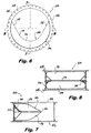
- FIG. 6 is a plan view of the deflector assembly of FIG. 5 , showing the sloping downstream surface of the deflector;
- FIG. 7 is a cross-sectional side elevation view of the deflector assembly of FIG. 6 , taken along section line 7 - 7 to show the radial cross-sectional profile of the deflector assembly of FIG. 6 adjacent to the circular portion of the inner periphery thereof, and
- FIG. 8 is a cross-sectional side elevation view of the deflector assembly of FIG. 6 , taken along section line 8 - 8 to show the radial cross-sectional profile of the portions of the deflector adjacent to the straight portions of the inner periphery thereof.
- FIG. 2 a partial view of an exemplary embodiment of a deflector device in accordance with the invention is shown in FIG. 2 and is designated generally by reference character 100 .
- FIGS. 3-8 Other embodiments of deflector devices in accordance with the invention, or aspects thereof, are provided in FIGS. 3-8 , as will be described.
- the systems and methods of the invention can be used in coal piping systems, or in any other suitable application, for enhanced particle distribution in a mixed flow of gas and solid particles.
- a typical coal power system 1 includes a mill or other pulverizing means for supplying fine coal particles for combustion.
- Coal fines are conveyed through system 1 in gas/particle mixtures.
- Particles entering elbow 2 downstream of the mill tend to concentrate on the outside of the corner of the elbow, and remain along the same edge through subsequent pipes 3 .
- This concentrated flow of particles clings to one side of pipes 3 , past rejects pipe 4 , through inner cone 5 and into classifier vanes 6 .
- the concentration of particles is greater on one side of pipes 3 entering inner cone 5 of the classifier, some of classifier vanes 6 receive much higher concentrations of coal particles than others, as indicated by stippling in FIG. 1 . This leads to uneven wear and under utilization of portions of the classifier.
- FIG. 2 shows a system 10 in accordance with the present invention, having inlet elbow 20 , coal pipes 30 , rejects pipe 40 , inner classifier cone 50 , and classifier vanes 60 , much as described above with respect to FIG. 1 .
- the coal particle distribution around inner cone 50 and classifier vanes 60 is significantly more even in system 10 than in system 1 due to deflector device 100 downstream of inlet elbow 20 deflecting and redistributing the stream of coal particles 35 away from the pipe walls and into the center of pipes 30 , as indicated in FIG. 2 .
- deflector device 100 includes a base 102 defining an outer circumference 104 .
- the base is configured to be mounted inside a pipe such that base 102 extends partially around the inner circumference of the pipe with the circumferences of the pipe and of base 102 (e.g., circumference 104 and the corresponding pipe circumference) being substantially aligned concentrically (as indicated in FIG. 2 ).
- a deflector 106 extends radially inward from base 102 .
- the upstream surface 108 of deflector 106 slopes concavely between base 102 and a radially inner periphery 110 of deflector 106 .
- Deflector 106 is configured to direct a concentrated flow of coal particles toward the center of the pipe (e.g., stream 35 in FIG. 2 ).
- deflector device 100 creates regions of cross mixing using its combination sloped, straight, and circular portions. In conjunction with the portion of rejects pipe 40 inside coal pipes 30 and inner cone 50 , deflector device 100 provides a substantially uniform distribution of coal particles to classifier vanes 60 . Rejects pipe 40 can be advantageously shielded against stream 35 of coal particles impacting thereagainst with a protective liner.
- inner periphery 110 of deflector 106 defines a substantially circular section 112 disposed circumferentially between substantially straight sections 114 .
- a single straight section 114 is disposed tangent to each side of circular section 112 , with circular section 112 circumferentially centered between straight sections 114 .
- Straight sections 114 extend from circular section 112 outward to outer circumference 104 defined by base 102 .
- Deflector device 100 can advantageously include a ceramic-type material, which provides for a long wear life of the device.
- Base 102 and other portions of deflector device 100 can be formed by casting in a monolithic casting.
- deflector device 100 can be used in an assembly that includes a spool piece 150 having a generally cylindrical interior.
- Spool piece 150 is configured to be joined between end flanges of adjacent pipes in a coal piping system such that the cylindrical interior of spool piece 150 is generally aligned with the interiors of the adjacent pipes (as shown in FIG. 2 ).
- Base 102 can be mounted inside spool piece 150 such that base 102 extends partially around the inner circumference of spool piece 150 with the circumferences of spool piece 150 and base 102 being substantially aligned concentrically, as shown in FIG. 6 .
- Spool piece 150 includes opposed end flanges 156 configured and adapted to join spool piece 156 between end flanges of two adjacent pipes in a coal piping system (as indicated in FIG. 2 ). As shown in FIGS. 5-6 , end flanges 156 of spool piece 150 each define a plurality of bores 158 for bolting spool piece 150 into place between two adjacent pipes to minimize the need for modifications to the surrounding system. There is often enough play between adjacent pipes to accommodate a spool piece without needing to modify other portions of the coal piping system.
- Spool piece 150 can be adjusted circumferentially in increments of between about 10 and about 15 degrees, depending on how it is bolted between the adjacent pipes. This allows for a degree of fine tuning to provide good particle distribution when installed in a given system. Optimal orientation of the features of deflector device 100 within the corresponding pipe can further improve particle distribution. It is advantageous to center circular section 112 of deflector device 100 where the coal particle concentration is highest upstream of device 100 .
- end components 118 are included on deflector device 100 adjacent the straight portions of inner periphery 110 .
- a downstream sloping component 116 is included on the downside portion of deflector device 100 .
- Components 116 and 118 are optional additions that can be included for ease of manufacture and to discourage build up of flammable particles, for example, immediately downstream of deflector device 100 .
- Substantially all of deflector 100 has a radial cross-section that is generally triangular, as shown in the cross-sectional portions of FIGS. 7-8 , taken along section lines 7 - 7 and 8 - 8 of FIG. 6 , respectively. As shown in FIGS.
- sloping surface 108 includes a two-layered construction.
- the two layers can include a support base, which can be formed first, and then a ceramic-type material, which can be applied to that base layer.
- the base may include anchor structures to accept ceramic castable material forming the outer layer.
- deflector device 100 allows it to streamline and center a concentration of coal particles unevenly following the boundary of coal pipes downstream of an elbow.
- Device 100 also serves to break the concentration of the particles up, in conjunction with the portion of rejecter pipe 40 and inner cone 50 .
- the result is that the coal particles supplied to the classifier vanes 60 are substantially more evenly distributed when compared to the known systems. This reduces erosion and the need for replacement parts and more fully utilizes the classifier vanes.
- Deflector devices in accordance with the invention can be installed with or without a spool piece in new or existing systems without departing from the spirit and scope of the invention.
- the methods and devices of the present invention provide for a deflector for a coal piping system with superior properties including the ability to provide improved coal particle distribution to a coal classifier, while causing little impact on pressure drop in the system. While described above in the context of a coal piping system, those skilled in the art will readily appreciate that the methods and devices described above can be used in any other suitable application for improving particle distribution within a mixed gas/particle flow. While the apparatus and methods of the subject invention have been shown and described with reference to preferred embodiments, those skilled in the art will readily appreciate that changes and/or modifications may be made thereto without departing from the spirit and scope of the subject invention.
Landscapes
- Engineering & Computer Science (AREA)
- Chemical & Material Sciences (AREA)
- Mechanical Engineering (AREA)
- Chemical Kinetics & Catalysis (AREA)
- General Engineering & Computer Science (AREA)
- Dispersion Chemistry (AREA)
- Combustion & Propulsion (AREA)
- Crushing And Grinding (AREA)
- Furnace Charging Or Discharging (AREA)
- Pipe Accessories (AREA)
- Solid Fuels And Fuel-Associated Substances (AREA)
- Supports For Pipes And Cables (AREA)
- Disintegrating Or Milling (AREA)
Abstract
Description
Claims (16)
Priority Applications (6)
| Application Number | Priority Date | Filing Date | Title |
|---|---|---|---|
| US12/196,031 US8104412B2 (en) | 2008-08-21 | 2008-08-21 | Deflector device for coal piping systems |
| CA2733238A CA2733238C (en) | 2008-08-21 | 2009-08-12 | Deflector device for coal piping systems |
| CN200980131773.0A CN102124271B (en) | 2008-08-21 | 2009-08-12 | Deflector device for coal piping systems |
| JP2011523871A JP5443489B2 (en) | 2008-08-21 | 2009-08-12 | Baffle device in a coal conduit system. |
| EP09808619A EP2324290B1 (en) | 2008-08-21 | 2009-08-12 | Deflector device for coal piping systems |
| PCT/US2009/053592 WO2010021892A2 (en) | 2008-08-21 | 2009-08-12 | Deflector device for coal piping systems |
Applications Claiming Priority (1)
| Application Number | Priority Date | Filing Date | Title |
|---|---|---|---|
| US12/196,031 US8104412B2 (en) | 2008-08-21 | 2008-08-21 | Deflector device for coal piping systems |
Publications (2)
| Publication Number | Publication Date |
|---|---|
| US20100044282A1 US20100044282A1 (en) | 2010-02-25 |
| US8104412B2 true US8104412B2 (en) | 2012-01-31 |
Family
ID=41695361
Family Applications (1)
| Application Number | Title | Priority Date | Filing Date |
|---|---|---|---|
| US12/196,031 Expired - Fee Related US8104412B2 (en) | 2008-08-21 | 2008-08-21 | Deflector device for coal piping systems |
Country Status (6)
| Country | Link |
|---|---|
| US (1) | US8104412B2 (en) |
| EP (1) | EP2324290B1 (en) |
| JP (1) | JP5443489B2 (en) |
| CN (1) | CN102124271B (en) |
| CA (1) | CA2733238C (en) |
| WO (1) | WO2010021892A2 (en) |
Cited By (3)
| Publication number | Priority date | Publication date | Assignee | Title |
|---|---|---|---|---|
| US20100123027A1 (en) * | 2008-11-14 | 2010-05-20 | Larue Albert D | Bladed coal diffuser and coal line balancing device |
| US20120104055A1 (en) * | 2010-10-27 | 2012-05-03 | Alstom Technology Ltd | Flow deflectors for fuel nozzles |
| US20160377100A1 (en) * | 2015-06-24 | 2016-12-29 | The Boeing Company | Flow Straightener Apparatus and Systems for Ducted Air |
Families Citing this family (5)
| Publication number | Priority date | Publication date | Assignee | Title |
|---|---|---|---|---|
| US20120183913A1 (en) * | 2011-01-13 | 2012-07-19 | White David C | Tower distribution in a coal burning power plant |
| JP5787789B2 (en) * | 2012-02-28 | 2015-09-30 | 三菱日立パワーシステムズ株式会社 | Pulverized coal adjustment device |
| JP6408135B2 (en) | 2015-03-31 | 2018-10-17 | 三菱日立パワーシステムズ株式会社 | Combustion burner and boiler equipped with the same |
| JP6408134B2 (en) * | 2015-03-31 | 2018-10-17 | 三菱日立パワーシステムズ株式会社 | Combustion burner and boiler |
| JP6642912B2 (en) | 2015-09-11 | 2020-02-12 | 三菱日立パワーシステムズ株式会社 | Combustion burner and boiler provided with the same |
Citations (23)
| Publication number | Priority date | Publication date | Assignee | Title |
|---|---|---|---|---|
| US1315719A (en) | 1916-07-07 | 1919-09-09 | Comb Economy Corp | Apparatus for burning powdered coal. |
| US3511445A (en) | 1968-04-05 | 1970-05-12 | Ronald A Ashdown | Air flow control means for pulverizing mill |
| US4186599A (en) | 1976-12-29 | 1980-02-05 | Rosemount Inc. | Vortex shedding flowmeter assembly |
| US4223615A (en) | 1978-08-07 | 1980-09-23 | Kvb, Inc. | Low nox coal burner |
| EP0076660A1 (en) | 1981-10-01 | 1983-04-13 | Babcock Spraymixer Limited | Improvements in or relating to the distribution of particulate material |
| US4380202A (en) * | 1981-01-14 | 1983-04-19 | The Babcock & Wilcox Company | Mixer for dual register burner |
| US5421274A (en) * | 1993-12-21 | 1995-06-06 | Combustion Engineering, Inc. | Coal fired steam generation apparatus with easily accessible coal pipe orifice |
| US5568777A (en) | 1994-12-20 | 1996-10-29 | Duquesne Light Company | Split flame burner for reducing NOx formation |
| US5593131A (en) | 1995-11-13 | 1997-01-14 | Db Riley, Inc. | Variable orifice plate for coal pipes |
| US5937770A (en) * | 1996-05-24 | 1999-08-17 | Babcock-Hitachi Kabushiki Kaisha | Pulverized coal burner |
| US6234090B1 (en) | 1999-08-31 | 2001-05-22 | Sure Alloy Steel Corporation | Linear diffuser for balancing coal flow |
| US6237510B1 (en) * | 1996-07-19 | 2001-05-29 | Babcock-Hitachi Kabushiki Kaisha | Combustion burner and combustion device provided with same |
| US6257415B1 (en) | 1999-11-15 | 2001-07-10 | Sure Alloy Steel Corporation | Multi-outlet diffuser system for classifier cones |
| US6474250B1 (en) | 2001-05-24 | 2002-11-05 | Babcock Borsig Power, Inc. | Nozzle assembly for a pulverized coal burner |
| US6588598B2 (en) | 1999-11-15 | 2003-07-08 | Rickey E. Wark | Multi-outlet diffuser system for classifier cones |
| US6607079B2 (en) | 2001-08-16 | 2003-08-19 | Foster Wheeler Energy Corporation | System and method for controlling particle flow distribution between the outlets of a classifier |
| US6840183B2 (en) | 1999-11-15 | 2005-01-11 | Rickey E. Wark | Diffuser insert for coal fired burners |
| US20050042043A1 (en) | 2000-04-24 | 2005-02-24 | Kenneth Levy | Adjustable air foils for balancing pulverized coal flow at a coal pipe splitter junction |
| US6899041B2 (en) | 2003-04-17 | 2005-05-31 | Rickey E. Wark | Multi-spin mixer for particulate coal supply conduit |
| US20070214896A1 (en) | 2002-04-09 | 2007-09-20 | Dieterich Standard, Inc. | Averaging orifice primary flow element |
| US20070281265A1 (en) * | 2006-06-01 | 2007-12-06 | Hamid Sarv | Large diameter mid-zone air separation cone for expanding IRZ |
| US20080210325A1 (en) * | 2005-05-11 | 2008-09-04 | Abdelwahab Aroussi | Distributor |
| US7665408B2 (en) * | 2001-11-16 | 2010-02-23 | Hitachi, Ltd. | Solid fuel burner, burning method using the same, combustion apparatus and method of operating the combustion apparatus |
Family Cites Families (14)
| Publication number | Priority date | Publication date | Assignee | Title |
|---|---|---|---|---|
| JPS60188725A (en) * | 1984-03-08 | 1985-09-26 | Isobe Tekko Kk | Uniformly distributing device for pulverized coal in pulverized coal burning boiler |
| GR862922B (en) * | 1986-12-18 | 1987-01-12 | Himikes Viomihanies Voreiou El | Tubular reactor |
| JPH08303748A (en) * | 1995-05-01 | 1996-11-22 | Mitsubishi Heavy Ind Ltd | Powder particle transferring pipe protection device |
| CA2221158C (en) * | 1995-05-09 | 2006-08-08 | Labatt Brewing Company Limited | Static fluid flow mixing apparatus |
| JPH0942649A (en) * | 1995-07-25 | 1997-02-14 | Babcock Hitachi Kk | Pulverized coal conveyance tube bend |
| JP3758742B2 (en) * | 1996-04-12 | 2006-03-22 | 財団法人電力中央研究所 | Concentration adjustment ring for pulverized coal burner |
| JP2995013B2 (en) * | 1997-03-31 | 1999-12-27 | 三菱重工業株式会社 | Pulverized fuel combustion burner |
| US6109781A (en) * | 1999-02-16 | 2000-08-29 | Ogasawara; Toshiyuki | Element of a mixing apparatus |
| FR2807479B1 (en) * | 2000-04-07 | 2002-06-07 | Gilbert Picard | DEVICE WHICH ATTENUATES INTRATUBULAR JAM AND BUFFERING EFFECTS CAUSED BY TURBULENT FLUIDS LOCATED UPSTREAM AND INSIDE A TEE AT 90° OF A CYLINDRICAL CONDUIT |
| GB0009890D0 (en) * | 2000-04-20 | 2000-06-07 | Thames Water Utilities | Flow deflecting device |
| CN2432448Y (en) * | 2000-05-22 | 2001-05-30 | 王炜 | Energy-saving environmental protection straight-flow coal powder burner |
| CN201028510Y (en) * | 2007-02-05 | 2008-02-27 | 郭永浩 | A blunt pulverized coal burner |
| CN100532935C (en) * | 2007-05-18 | 2009-08-26 | 哈尔滨工业大学 | Energy saving micro oil and natural gas igniting powder coal burner |
| CN201081246Y (en) * | 2007-09-05 | 2008-07-02 | 曲大伟 | Plasma igniter with rake-type powdered coal distribution guide plate |
-
2008
- 2008-08-21 US US12/196,031 patent/US8104412B2/en not_active Expired - Fee Related
-
2009
- 2009-08-12 CN CN200980131773.0A patent/CN102124271B/en not_active Expired - Fee Related
- 2009-08-12 WO PCT/US2009/053592 patent/WO2010021892A2/en not_active Ceased
- 2009-08-12 EP EP09808619A patent/EP2324290B1/en not_active Not-in-force
- 2009-08-12 JP JP2011523871A patent/JP5443489B2/en not_active Expired - Fee Related
- 2009-08-12 CA CA2733238A patent/CA2733238C/en not_active Expired - Fee Related
Patent Citations (24)
| Publication number | Priority date | Publication date | Assignee | Title |
|---|---|---|---|---|
| US1315719A (en) | 1916-07-07 | 1919-09-09 | Comb Economy Corp | Apparatus for burning powdered coal. |
| US3511445A (en) | 1968-04-05 | 1970-05-12 | Ronald A Ashdown | Air flow control means for pulverizing mill |
| US4186599A (en) | 1976-12-29 | 1980-02-05 | Rosemount Inc. | Vortex shedding flowmeter assembly |
| US4223615A (en) | 1978-08-07 | 1980-09-23 | Kvb, Inc. | Low nox coal burner |
| US4380202A (en) * | 1981-01-14 | 1983-04-19 | The Babcock & Wilcox Company | Mixer for dual register burner |
| EP0076660A1 (en) | 1981-10-01 | 1983-04-13 | Babcock Spraymixer Limited | Improvements in or relating to the distribution of particulate material |
| US5421274A (en) * | 1993-12-21 | 1995-06-06 | Combustion Engineering, Inc. | Coal fired steam generation apparatus with easily accessible coal pipe orifice |
| US5568777A (en) | 1994-12-20 | 1996-10-29 | Duquesne Light Company | Split flame burner for reducing NOx formation |
| US5593131A (en) | 1995-11-13 | 1997-01-14 | Db Riley, Inc. | Variable orifice plate for coal pipes |
| US5685240A (en) | 1995-11-13 | 1997-11-11 | Db Riley, Inc. | Variable orifice plate for coal pipes |
| US5937770A (en) * | 1996-05-24 | 1999-08-17 | Babcock-Hitachi Kabushiki Kaisha | Pulverized coal burner |
| US6237510B1 (en) * | 1996-07-19 | 2001-05-29 | Babcock-Hitachi Kabushiki Kaisha | Combustion burner and combustion device provided with same |
| US6234090B1 (en) | 1999-08-31 | 2001-05-22 | Sure Alloy Steel Corporation | Linear diffuser for balancing coal flow |
| US6257415B1 (en) | 1999-11-15 | 2001-07-10 | Sure Alloy Steel Corporation | Multi-outlet diffuser system for classifier cones |
| US6588598B2 (en) | 1999-11-15 | 2003-07-08 | Rickey E. Wark | Multi-outlet diffuser system for classifier cones |
| US6840183B2 (en) | 1999-11-15 | 2005-01-11 | Rickey E. Wark | Diffuser insert for coal fired burners |
| US20050042043A1 (en) | 2000-04-24 | 2005-02-24 | Kenneth Levy | Adjustable air foils for balancing pulverized coal flow at a coal pipe splitter junction |
| US6474250B1 (en) | 2001-05-24 | 2002-11-05 | Babcock Borsig Power, Inc. | Nozzle assembly for a pulverized coal burner |
| US6607079B2 (en) | 2001-08-16 | 2003-08-19 | Foster Wheeler Energy Corporation | System and method for controlling particle flow distribution between the outlets of a classifier |
| US7665408B2 (en) * | 2001-11-16 | 2010-02-23 | Hitachi, Ltd. | Solid fuel burner, burning method using the same, combustion apparatus and method of operating the combustion apparatus |
| US20070214896A1 (en) | 2002-04-09 | 2007-09-20 | Dieterich Standard, Inc. | Averaging orifice primary flow element |
| US6899041B2 (en) | 2003-04-17 | 2005-05-31 | Rickey E. Wark | Multi-spin mixer for particulate coal supply conduit |
| US20080210325A1 (en) * | 2005-05-11 | 2008-09-04 | Abdelwahab Aroussi | Distributor |
| US20070281265A1 (en) * | 2006-06-01 | 2007-12-06 | Hamid Sarv | Large diameter mid-zone air separation cone for expanding IRZ |
Non-Patent Citations (4)
| Title |
|---|
| International Search Report for PCT/US09/37274, dated May 14, 2009. |
| International Search Report for PCT/US2009/053592, dated Mar. 17, 2010. |
| Written Opinion of the International Searching Authority for PCT/US09/37274, dated May 14, 2009. |
| Written Opinion of the International Searching Authority for PCT/US2009/053592, dated Mar. 17, 2010. |
Cited By (8)
| Publication number | Priority date | Publication date | Assignee | Title |
|---|---|---|---|---|
| US20100123027A1 (en) * | 2008-11-14 | 2010-05-20 | Larue Albert D | Bladed coal diffuser and coal line balancing device |
| US8991323B2 (en) * | 2008-11-14 | 2015-03-31 | Babcock & Wilcox Power Generation Group, Inc. | Bladed coal diffuser and coal line balancing device |
| US20120104055A1 (en) * | 2010-10-27 | 2012-05-03 | Alstom Technology Ltd | Flow deflectors for fuel nozzles |
| US9388982B2 (en) * | 2010-10-27 | 2016-07-12 | Alstom Technology Ltd | Flow deflectors for fuel nozzles |
| US20160377100A1 (en) * | 2015-06-24 | 2016-12-29 | The Boeing Company | Flow Straightener Apparatus and Systems for Ducted Air |
| CN106275451A (en) * | 2015-06-24 | 2017-01-04 | 波音公司 | Rectifier unit and system for pipeline air |
| US9732775B2 (en) * | 2015-06-24 | 2017-08-15 | The Boeing Company | Flow straightener apparatus and systems for ducted air |
| CN106275451B (en) * | 2015-06-24 | 2021-06-01 | 波音公司 | Rectifier device and system for duct air |
Also Published As
| Publication number | Publication date |
|---|---|
| EP2324290A2 (en) | 2011-05-25 |
| JP5443489B2 (en) | 2014-03-19 |
| CA2733238C (en) | 2016-11-29 |
| CN102124271A (en) | 2011-07-13 |
| EP2324290B1 (en) | 2012-11-14 |
| WO2010021892A3 (en) | 2010-06-10 |
| JP2012500383A (en) | 2012-01-05 |
| EP2324290A4 (en) | 2011-08-03 |
| CN102124271B (en) | 2014-03-12 |
| WO2010021892A2 (en) | 2010-02-25 |
| US20100044282A1 (en) | 2010-02-25 |
| CA2733238A1 (en) | 2010-02-25 |
Similar Documents
| Publication | Publication Date | Title |
|---|---|---|
| CA2733238C (en) | Deflector device for coal piping systems | |
| EP2479494B1 (en) | Coal particle flow balancing device | |
| JP6016395B2 (en) | Coal flow distributor and distributor | |
| EP2379943B1 (en) | Head assembly for coal nozzle | |
| JP5260034B2 (en) | Powder separator and solid fuel burner | |
| US9829196B2 (en) | Housing assembly for a flare tip apparatus for use on a waste gas flare stack | |
| US5588380A (en) | Diffuser for coal nozzle burner | |
| US9857077B2 (en) | Coal rope distributor with replaceable wear components | |
| US8082860B2 (en) | Anti-roping device for pulverized coal burners | |
| US5526758A (en) | Distribution cone for pulverized coal burners | |
| US7810441B2 (en) | Coal burner assembly | |
| US20120272875A1 (en) | Burner for Particulate Fuel | |
| US20120037054A1 (en) | Burner | |
| CN217928748U (en) | Useless combustor nozzle of handling of danger | |
| JPH0942649A (en) | Pulverized coal conveyance tube bend | |
| CN117869882A (en) | Hydrogen burner and hydrogen-blended combustion system containing the same |
Legal Events
| Date | Code | Title | Description |
|---|---|---|---|
| AS | Assignment |
Owner name: RILEY POWER, INC.,MASSACHUSETTS Free format text: ASSIGNMENT OF ASSIGNORS INTEREST;ASSIGNORS:ZARNESCU, VLAD;PENTERSON, CRAIG A.;REEL/FRAME:021606/0855 Effective date: 20080912 Owner name: RILEY POWER, INC., MASSACHUSETTS Free format text: ASSIGNMENT OF ASSIGNORS INTEREST;ASSIGNORS:ZARNESCU, VLAD;PENTERSON, CRAIG A.;REEL/FRAME:021606/0855 Effective date: 20080912 |
|
| AS | Assignment |
Owner name: BANK OF AMERICA, N.A., AS ADMINISTRATIVE AGENT,TEX Free format text: NOTICE OF GRANT OF SECURITY INTEREST IN PATENTS;ASSIGNOR:RILEY POWER INC.;REEL/FRAME:024505/0181 Effective date: 20100527 Owner name: BANK OF AMERICA, N.A., AS ADMINISTRATIVE AGENT, TE Free format text: NOTICE OF GRANT OF SECURITY INTEREST IN PATENTS;ASSIGNOR:RILEY POWER INC.;REEL/FRAME:024505/0181 Effective date: 20100527 |
|
| ZAAA | Notice of allowance and fees due |
Free format text: ORIGINAL CODE: NOA |
|
| ZAAB | Notice of allowance mailed |
Free format text: ORIGINAL CODE: MN/=. |
|
| ZAAA | Notice of allowance and fees due |
Free format text: ORIGINAL CODE: NOA |
|
| STCF | Information on status: patent grant |
Free format text: PATENTED CASE |
|
| FPAY | Fee payment |
Year of fee payment: 4 |
|
| MAFP | Maintenance fee payment |
Free format text: PAYMENT OF MAINTENANCE FEE, 8TH YEAR, LARGE ENTITY (ORIGINAL EVENT CODE: M1552); ENTITY STATUS OF PATENT OWNER: LARGE ENTITY Year of fee payment: 8 |
|
| FEPP | Fee payment procedure |
Free format text: MAINTENANCE FEE REMINDER MAILED (ORIGINAL EVENT CODE: REM.); ENTITY STATUS OF PATENT OWNER: LARGE ENTITY |
|
| LAPS | Lapse for failure to pay maintenance fees |
Free format text: PATENT EXPIRED FOR FAILURE TO PAY MAINTENANCE FEES (ORIGINAL EVENT CODE: EXP.); ENTITY STATUS OF PATENT OWNER: LARGE ENTITY |
|
| STCH | Information on status: patent discontinuation |
Free format text: PATENT EXPIRED DUE TO NONPAYMENT OF MAINTENANCE FEES UNDER 37 CFR 1.362 |
|
| FP | Lapsed due to failure to pay maintenance fee |
Effective date: 20240131 |