US8098448B2 - Method for setting zone format of a disk for storing data and disk drive - Google Patents
Method for setting zone format of a disk for storing data and disk drive Download PDFInfo
- Publication number
- US8098448B2 US8098448B2 US12/639,926 US63992609A US8098448B2 US 8098448 B2 US8098448 B2 US 8098448B2 US 63992609 A US63992609 A US 63992609A US 8098448 B2 US8098448 B2 US 8098448B2
- Authority
- US
- United States
- Prior art keywords
- data
- zone
- boundary
- sectors
- data sectors
- Prior art date
- Legal status (The legal status is an assumption and is not a legal conclusion. Google has not performed a legal analysis and makes no representation as to the accuracy of the status listed.)
- Expired - Fee Related
Links
Images


Classifications
-
- G—PHYSICS
- G11—INFORMATION STORAGE
- G11B—INFORMATION STORAGE BASED ON RELATIVE MOVEMENT BETWEEN RECORD CARRIER AND TRANSDUCER
- G11B20/00—Signal processing not specific to the method of recording or reproducing; Circuits therefor
- G11B20/10—Digital recording or reproducing
- G11B20/12—Formatting, e.g. arrangement of data block or words on the record carriers
- G11B20/1217—Formatting, e.g. arrangement of data block or words on the record carriers on discs
- G11B20/1258—Formatting, e.g. arrangement of data block or words on the record carriers on discs where blocks are arranged within multiple radial zones, e.g. Zone Bit Recording or Constant Density Recording discs, MCAV discs, MCLV discs
-
- G—PHYSICS
- G11—INFORMATION STORAGE
- G11B—INFORMATION STORAGE BASED ON RELATIVE MOVEMENT BETWEEN RECORD CARRIER AND TRANSDUCER
- G11B20/00—Signal processing not specific to the method of recording or reproducing; Circuits therefor
- G11B20/10—Digital recording or reproducing
- G11B20/12—Formatting, e.g. arrangement of data block or words on the record carriers
- G11B20/1217—Formatting, e.g. arrangement of data block or words on the record carriers on discs
- G11B2020/1218—Formatting, e.g. arrangement of data block or words on the record carriers on discs wherein the formatting concerns a specific area of the disc
- G11B2020/1242—Formatting, e.g. arrangement of data block or words on the record carriers on discs wherein the formatting concerns a specific area of the disc the area forming one or more zones, wherein each zone is shaped like an annulus or a circular sector
-
- G—PHYSICS
- G11—INFORMATION STORAGE
- G11B—INFORMATION STORAGE BASED ON RELATIVE MOVEMENT BETWEEN RECORD CARRIER AND TRANSDUCER
- G11B20/00—Signal processing not specific to the method of recording or reproducing; Circuits therefor
- G11B20/10—Digital recording or reproducing
- G11B20/12—Formatting, e.g. arrangement of data block or words on the record carriers
- G11B2020/1264—Formatting, e.g. arrangement of data block or words on the record carriers wherein the formatting concerns a specific kind of data
- G11B2020/1265—Control data, system data or management information, i.e. data used to access or process user data
- G11B2020/1281—Servo information
- G11B2020/1282—Servo information in embedded servo fields
-
- G—PHYSICS
- G11—INFORMATION STORAGE
- G11B—INFORMATION STORAGE BASED ON RELATIVE MOVEMENT BETWEEN RECORD CARRIER AND TRANSDUCER
- G11B20/00—Signal processing not specific to the method of recording or reproducing; Circuits therefor
- G11B20/10—Digital recording or reproducing
- G11B20/12—Formatting, e.g. arrangement of data block or words on the record carriers
- G11B2020/1291—Formatting, e.g. arrangement of data block or words on the record carriers wherein the formatting serves a specific purpose
- G11B2020/1292—Enhancement of the total storage capacity
-
- G—PHYSICS
- G11—INFORMATION STORAGE
- G11B—INFORMATION STORAGE BASED ON RELATIVE MOVEMENT BETWEEN RECORD CARRIER AND TRANSDUCER
- G11B2220/00—Record carriers by type
- G11B2220/20—Disc-shaped record carriers
- G11B2220/25—Disc-shaped record carriers characterised in that the disc is based on a specific recording technology
- G11B2220/2508—Magnetic discs
- G11B2220/2516—Hard disks
Definitions
- Embodiments of the present invention relate to a method for setting a zone format of a disk for storing data and a disk drive performing the method.
- Disk drives are known in the art that use various kinds of disks, such as: optical disks, magneto-optical disks, flexible magnetic-recording disks, and similar disk data-storage devices.
- disks such as: optical disks, magneto-optical disks, flexible magnetic-recording disks, and similar disk data-storage devices.
- HDDs hard-disk drives
- HDDs have been widely used as indispensable data-storage devices for current computer systems.
- HDDs have found widespread application to moving image recording and reproducing apparatuses, car navigation systems, cellular phones, and similar devices, in addition to the computers, due to their outstanding information-storage characteristics.
- a magnetic-recording disk used in a HDD has multiple concentric data tracks and servo tracks.
- a servo track consists of multiple servo sectors having address information.
- a data track consists of multiple data sectors containing user data.
- a data sector is recorded between separate servo sectors in the circumferential direction of the magnetic-recording disk.
- a magnetic-recording head of a head-slider supported by a rotary actuator accesses designated data sectors according to address information in servo sectors to write data to, and read data from, data sectors.
- Embodiments of the present invention include a method for dividing a data area on a disk into a plurality of concentric zones and determining a format for each zone so that data tracks in the zone have the same number of data sectors.
- the method includes dividing a data area into a plurality of zones with provisional boundaries.
- the method also includes determining a linear recording density for a selected zone.
- the method further includes selecting the number of data sectors per data track corresponding to the determined linear recording density from specified values.
- the method includes resetting a boundary of the zone at a new boundary shifted from the provisional boundary according to a selected value.
- FIG. 1 is a block diagram schematically illustrating the configuration of a hard-disk drive (HDD), in accordance with an embodiment of the present invention.
- HDD hard-disk drive
- FIGS. 2( a ) and 2 ( b ) are drawings schematically illustrating a recording surface of a magnetic-recording disk and the data format of a portion of the recording surface, respectively, in accordance with an embodiment of the present invention.
- FIG. 3 is a flowchart showing the flow of a process for setting bits per inch (BPIs) for all zones on a recording surface performed by the hard-disk controller/microprocessor unit (HDC/MPU), in accordance with an embodiment of the present invention.
- BPIs bits per inch
- FIG. 4 is a drawing schematically illustrating a method to measure error rates in three zones, Zn 1 , Zk ⁇ 1 and Z 0 , and to determine the relationship between the error rate and the BPI in the zones, in accordance with an embodiment of the present invention.
- FIG. 5 is a graph showing an example relationship between the BPI and the error rate in a zone, in accordance with an embodiment of the present invention.
- FIG. 6 is a graph showing an example of a modeling function showing the relationship between the radial position and the BPI_T, in accordance with an embodiment of the present invention.
- FIG. 7 is a flowchart showing the flow of a process including determining the BPI and resetting a boundary of each of the zones, in accordance with an embodiment of the present invention.
- FIG. 8 is a diagram showing the process including determining the BPI and resetting a boundary of each of the zones, in accordance with an embodiment of the present invention.
- FIGS. 9( a ), 9 ( b ) and 9 ( c ) are diagrams showing examples of resetting a number of data sectors and an inner boundary of the zone Zk, in accordance with an embodiment of the present invention.
- FIG. 10 is a drawing schematically illustrating a gap between a servo sector and a data sector, in accordance with an embodiment of the present invention.
- FIG. 11 is a drawing schematically illustrating a physical format of data recorded in a data track, in accordance with related art.
- a data track pitch may be set for each magnetic-recording head, which corresponds to each recording surface of the magnetic-recording disk.
- the data track pitch determined according to the properties of a magnetic-recording head such as read width, and write width, allows suppressing an effect on adjacent data tracks in writing of data, as well as, increasing the data capacity of a recording surface.
- a recording surface is divided into a plurality of zones in the radial direction and different linear recording densities, as measured by the parameter, known in the art as, “bits-per-inch,” or “BPI,” are assigned to the zones. Assigning higher BPIs to outer zones allows increasing the storage capacity of a recording surface.
- the recording frequency is constant, and the BPIs of data tracks are different.
- the innermost data track in a zone has the largest BPI.
- the error rate of a magnetic-recording disk depends on the BPI. The error rate increases with increasing BPI.
- the upper limit of error rate is defined in order to ensure reliability.
- the BPI is determined so that the error rate of each zone is less than a specified value.
- the error rate depends on the properties of a magnetic-recording head. Because recent advances in magnetic-recording technology have led to higher recording densities in HDDs, the error rate changes depending on the magnetic-recording-head manufacturing tolerances.
- the error rate of each zone is measured; and, a recording frequency is set that is appropriate for the magnetic-recording-head properties for each zone.
- the method writes and reads data in each zone with a magnetic-recording head and measures the error rate.
- the method sets the recording frequency corresponding to each zone so that the error rate is less than a specified value.
- error rate less than a specified value in each zone and specified storage capacity of a recording surface may be provided.
- a HDD stores user data in data sectors.
- a data sector has a specific format and stores a specific length of user data, for example, user data with a 512 byte length. Access of user data in a HDD is carried out by designating the addresses of the user data.
- a data sector is a unit of storing; and, a data track consists of a natural number of data sectors.
- a drawing is shown that schematically illustrates the physical format of data recorded in a data track.
- a data track includes a plurality of data sectors.
- three data sectors 131 a to 131 c are illustrated.
- Servo sectors are disposed at regular intervals to separate data sectors, or a single data sector.
- two servo sectors 132 a and 132 b are illustrated.
- the data sectors 131 a to 131 c in the data track can be categorized into two types. One is a split sector that is split by a servo sector 132 b ; and, the others are normal data sectors that are not split, referred to as non-split sectors. In the example of FIG. 11 , the data sectors 131 a and 131 b are not split by a servo sector and are normal sectors. On the other hand, the data sector 131 c is split by the servo sector 132 b and is a split sector.
- FIG. 11 illustrates the data format of the data sector 131 a as a non-split data sector.
- the data sector 131 a has the fields of sync (SYNC) 311 , data address mark (DAM) 312 , user data section 313 , cyclic redundancy check code (CRCC) 314 and error correction code (ECC) 315 .
- the BPI is defined by the user data section 313 .
- the BPI is determined by the number of bits in the user data section 313 and the length, for example, in units of an inch, of the user data section 313 .
- the BPI is also determined from the recording frequency and the radial position of a data track.
- the length of the user data section 313 changes with the radial position at the same data rate. In a zone, the BPI values of tracks decrease from the innermost data track toward the outermost data track.
- the sync 311 is a constant frequency signal.
- a PLL circuit in a RW channel operates in synchronization with the sync 311 ; and, a variable gain amplifier (VGA) adjusts the gain according to the sync 311 .
- VGA variable gain amplifier
- the DAM indicates the start of the user data and sync data for reading the subsequent user data.
- the CRCC 314 and the ECC 315 are added to correct errors in recording of data to a magnetic-recording disk.
- a HDD corrects errors in read data with the ECC 315 , and uses the CRCC 314 for checking the error correction.
- the split sector 131 c is split into two portions, a PART a and a PART b, by a servo sector 132 b .
- Each of the PART a and the PART b has the same format as the data sector 131 a . Therefore, the amount of data other than user data is larger in a split sector than a non-split sector.
- a split sector is more redundant than a non-split sector.
- reducing the number of split sectors in a data track allows increasing the user data capacity in the data track.
- the number of servo sectors on a recording surface is predefined. Therefore, if the number of data sectors contained in a data track is selected from values to reduce split sectors according to the number of servo sectors, the recording density of user data on a recording surface is increased.
- the number of data sectors included in a data track is the same in a zone. If the BPI of a zone is determined, the number of data sectors in a data track is determined.
- embodiments of the present invention provide a technique to determine the BPI to match with an efficient number of data sectors in a data track so as to increase the user data recording density, which determines the data capacity, on a recording surface.
- Embodiments of the present invention includes a method for dividing a data area on a disk into a plurality of concentric zones and determining a format for each zone so that data tracks in the zone have the same number of data sectors.
- the method divides a data area into a plurality of zones with provisional boundaries.
- the method determines a linear recording density for a selected zone.
- the method selects the number of data sectors per data track corresponding to the determined linear recording density from specified values.
- the method resets a boundary of the zone at a new boundary shifted from the provisional boundary according to a selected value.
- the method can increase the capacity of user data on a recording surface while setting an appropriate linear recording density for each zone.
- an error rate is measured in the data area, and the linear recording density is determined according to the error rate.
- the method allows determining a proper recording density for each head.
- error rates are measured in a portion of the plurality of zones and the relationship between the error rate and the linear recording density in the portion of the plurality of zones is determined; and, the linear recording density corresponding to a reference error rate of the selected zone is determined from the relationship.
- the method provides a more appropriate recording density.
- the error rate measurement in the data area measures an effect on an adjacent track by a recording element.
- the method allows more appropriately determining the recording density according to the error rate.
- the number of data sectors per data track at a provisional boundary of the zone corresponding to the linear recording density at the provisional boundary is calculated; and, a boundary of the zone is shifted according to a difference between the calculated number of data sectors and the selected value.
- the method provides an appropriate boundary according to the number of data sectors.
- the boundary of the zone is shifted inward from the provisional boundary if the selected value is less than the calculated number of data sectors.
- the method increases the data capacity.
- the boundary of the zone is shifted outward from the provisional boundary if the selected value is larger than the calculated number of data sectors.
- the method increases the data capacity.
- a value smaller than or larger than the calculated number of data sectors is selected from the specified values according to a specified condition; the boundary of the zone is shifted inward from the provisional boundary if the selected value is less than the calculated number of data sectors; and, the boundary of the zone is shifted outward from the provisional boundary if the selected value is larger than the calculated number of data sectors according to the selected value.
- the method allows determining a boundary so that the data capacity increases.
- the value closest to the calculated number of data sectors is selected from the specified values.
- the method allows determining an appropriate value for the number of data sectors.
- the calculation of the number of data sectors corrects variations in gaps between servo sectors and data sectors with the radial position on the disk.
- the method provides more precise calculation.
- a disk drive includes: a disk including a data area, a head for accessing the data area, a moving mechanism for supporting and moving the head in proximity with the data area, and a controller configured to divide the data area into a plurality of zones with provisional boundaries, configured to determine a linear recording density for a selected zone, configured to select the number of data sectors per data track corresponding to the determined linear recording density from specified values, and configured to reset a boundary of the zone at a new boundary shifted from the provisional boundary.
- the controller can increase the capacity of user data on a recording surface while setting an appropriate linear recording density for each zone.
- Embodiments of the present invention can increase the capacity of user data on a recording surface while setting an appropriate linear recording density for each zone.
- Embodiments of the present invention are subsequently described by way of example of: a hard-disk drive (HDD), which is an example of a disk drive; a magnetic-recording head, which is an example of a head; and, a magnetic-recording disk, which is an example of a disk.
- Embodiments of the present invention set the zone format of a recording surface.
- a method determines the linear recording density of each zone depending on measurement results on a recording surface with a magnetic-recording head.
- bits/inch is used as a unit of measurement of linear recording density.
- a measurement value for determining an appropriate BPI is an error rate.
- a BPI which is set for the error rate to satisfy a reference criterion achieves suitable performance and reliability of a HDD.
- the number of data sectors in a data track is constant and the BPI changes in the zone.
- the BPI of one data track is determined, the number of data sectors in each data track is determined in the zone and the BPIs of the other data tracks are determined.
- the BPI of the innermost data track is the largest. Thus, if the BPI of the innermost data track is determined so that a reference error rate is satisfied, the BPI and the reference error rate in the other outer data tracks are satisfied.
- the method selects the number of data sectors to be assigned to each zone from specified numbers.
- the number of data sectors to be assigned to each zone is not arbitrary, but selected from a group of predetermined numbers.
- the number of data sectors is selected so that the number of split sectors in a data track is a specified number or less.
- embodiments of the present invention reduce the redundancy in the data track and increase the storage capacity of user data, for example, as measured by recording density per data track.
- the method selects the number of data sectors corresponding to an appropriate BPI determined by measurement from the specified group and assigns the value to a zone. Further, in accordance with embodiments of the present invention, the method resets the boundary of the zone according to the assigned number of data sectors. Thus, in accordance with embodiments of the present invention, the data capacity of the recording surface is increased.
- zone format setting in accordance with embodiments of the present invention, the configuration of a HDD is next described.
- HDD 1 has a circuit board 20 fixed on the outer surface of a disk enclosure (DE) 10 .
- circuit elements are mounted such as a read/write channel (RW channel) 21 , a motor driver unit 22 , an integrated circuit that is a hard disk controller/microprocessor unit (HDC/MPU) 23 , and a random access memory (RAM) 24 .
- RW channel read/write channel
- HDC/MPU hard disk controller/microprocessor unit
- RAM random access memory
- a spindle motor (SPM) 14 spins a magnetic-recording disk 11 , which is a disk for storing data, at a specific angular rate.
- the motor driver unit 22 drives SPM 14 according to control data from HDC/MPU 23 .
- Each of the head-sliders 12 includes a slider for flying in proximity with the recording surface of the magnetic-recording disk, and a magnetic-recording head secured on the slider for carrying out the conversion between magnetic signals and electric signals.
- An arm electronics (AE) module 13 selects a head-slider 12 to access, for example, for reading data from, or writing data to, the magnetic-recording disk 11 from the plurality of head-sliders 12 according to control data from HDC/MPU 23 , and amplifies read-back signals and write signals.
- the head-sliders 12 are fixed at the distal end portion of an actuator 16 .
- the actuator 16 is connected to a voice coil motor (VCM) 15 and rotates about a pivot shaft to move the head-sliders 12 in proximity with the recording surface of the spinning magnetic-recording disk 11 along the radial direction of the magnetic-recording disk 11 .
- VCM voice coil motor
- the assembly of the actuator 16 and the VCM 15 is a mechanism for moving the magnetic-recording head.
- the motor driver unit 22 drives the VCM 15 according to control data from HDC/MPU 23 .
- the RW channel 21 in a read operation, extracts data from the obtained read-back signals, and decodes the data.
- the decoded data are supplied to HDC/MPU 23 .
- the RW channel 21 in a write operation, code-modulates write data supplied from HDC/MPU 23 , converts the code-modulated data into write signals, and then supplies the write signals to the AE module 13 .
- the HDC in HDC/MPU 23 is a logic circuit; and, the MPU operates in accordance with micro-codes loaded to RAM 24 .
- HDC/MPU 23 is an example of a controller; and, HDC/MPU 23 performs the control of HDD 1 in addition to other processes concerning data processing, such as: positioning control, interface control, and defect management.
- FIGS. 2( a ) and 2 ( b ) a drawing is shown in FIG. 2( a ) that schematically illustrates the data configuration on a recording surface of the magnetic-recording disk 11 ; and, in FIG. 2 ( b ), a drawing is shown that schematically illustrates the data format of a portion of the recording surface.
- a plurality of servo regions 111 extending radially and formed at regular intervals in the circumferential direction and data regions 112 each of which is provided between two adjoining servo regions 111 are formed on the recording surface of the magnetic-recording disk 11 .
- Servo data for positioning control of the head-slider 12 are recorded in each servo region 111 .
- User data and data used for the control of HDD 1 are recorded in data areas 112 .
- Concentric data tracks 114 are formed on a recording surface of the magnetic-recording disk 11 .
- the data track (DTr) 114 has a specific width in the radial direction. User data are recorded along the data tracks 114 .
- One data track 114 includes a data sector, a recording unit for user data, and typically consists of a plurality of data sectors. Data sectors contain user data with the same data length and the addresses of data sectors are designated in reading operations, or writing operations, of user data.
- Data tracks on a recording surface are grouped into a plurality of zones according to the radial positions. Each zone consists of consecutive data tracks in the radial direction.
- FIG. 2 ( a ) three zones 113 a to 113 c are illustrated.
- a track per inch (TPI), which is data track density, and a BPI are set for each zone.
- the magnetic-recording disk 11 has concentric servo tracks 115 .
- a servo track (STr) 115 has a specific width in the radial direction and consists of multiple servo sectors separated by data regions 112 .
- a servo sector includes: a servo track number, a servo sector number in the servo track, and a burst pattern for fine positioning. The amplitude of the read-back signal of the burst pattern can determine the position in the servo track.
- the servo track pitch and the data track pitch in the user area do not coincide with each other on a recording surface.
- Data track pitches are determined individually according to the properties of head-sliders 12 . Determining the data track pitch for each head-slider 12 provides the optimum data track pitch for the properties of head-slider 12 , reduction of the effect on adjacent data tracks in data writing, and an increase in the storage capacity, as provided by an increase in the number of data tracks.
- Embodiments of the present invention can also be applied to a format in which the data track pitch and the servo track pitch coincide with each other.
- the present embodiment provides for setting the BPI of each zone.
- a BPI setting method in setting a zone format is next described specifically. Setting of a zone format is performed after assembling a head disk assembly (HDA), which is an assembly obtained by removing the circuit board 20 from the HDD 1 , and the servo writing operation in manufacturing of HDD 1 .
- HDA head disk assembly
- the controller on the control circuit board to be mounted on HDD 1 may set the zone format.
- the controller to be included in the product HDD 1 sets the zone format. Whichever of the product controller or the dedicated controller performs the process, a HDD includes a HDA and a controller.
- a flowchart depicts the flow of a process for setting BPIs for all zones on a recording surface performed by HDC/MPU 23 .
- HDC/MPU 23 performs and controls a zone format setting process.
- HDC/MPU 23 sets a BPI after setting a TPI for each zone.
- HDC/MPU 23 divides a selected recording surface into a plurality of zones at provisional boundaries. Methods for determining the provisional boundaries are not restricted; and, typically preset provisional boundaries, for example, as given by a specified rule to determine boundaries, exist. For example, provisional boundaries and the TPI of each zone are predefined according to the data capacity specified for the recording surface.
- HDC/MPU 23 measures the error rates in zones selected from the plurality of zones defined by the provisional boundaries.
- HDC/MPU 23 measures the error rates in three zones, Zn 1 , Zk ⁇ 1 and Z 0 , and determines the relationship between error rates and BPIs in the zones.
- HDC/MPU 23 measures the error rates at data tracks Trn ⁇ 1, Trk ⁇ 1 and Tr 0 in the zones.
- HDC/MPU 23 controls the actuator 16 to move the head-slider 12 to a target data track and writes data at a specific recording frequency, which is determined by the BPI, with the head-slider 12 .
- HDC/MPU 23 writes and reads all data sectors in a data track and calculates the average of the error rate by reading multiple times.
- HDC/MPU 23 may use another error rate measurement method.
- the error rate is an indicator for the performance and reliability of HDD 1 . Since the error rate changes with the BPI, the error rate may provide an indicator for a BPI setting. However, if another indicator different from an error rate exists for determining the BPIs of zones, HDC/MPU 23 may determine the BPIs according to that other indicator. The HDC/MPU 23 measures the error rates at different BPIs on one or more data tracks in each zone. Thus, in accordance with embodiments of the present invention, the relationship between the BPI and the error rate in each zone can be determined.
- a graph is shown that schematically depicts the relationship between the BPI and the error rate in a zone.
- the black filled circles are measurement values and the curve is a modeling function based on the measurement values.
- a recording surface is divided into n zones from Z 0 to Zn ⁇ 1; and, HDC/MPU 23 obtains three graphs, which provide functions, for three zones, Zn ⁇ 1, Zk ⁇ 1 and Z 0 .
- An error rate is preset in HDD 1 .
- the preset error rate provides a ceiling of error rate for a recording surface.
- HDC/MPU 23 determines the BPI of each zone so that the error rates at all data tracks are below the ceiling limit.
- HDC/MPU 23 calculates the BPI (BPI_T) corresponding to the specified error rate (SER_T) from a function obtained by error rate measurement in each zone.
- HDC/MPU 23 measures the error rates in a portion of zones in order to reduce measurement time. However, HDC/MPU 23 may measure error rates in all zones. HDC/MPU 23 may measure error rates on data tracks in a zone. Thus, in an embodiment of the present invention, measuring error rates at data tracks in each of selected zones provides for balancing efficiency and accuracy of measurement.
- HDC/MPU 23 calculates the relationship between the radial position on a recording surface of the magnetic-recording disk 11 and the BPI ceiling value BPI_T from the error rate measurement result, which is the relational expression of the graph shown in FIG. 5 .
- the radial position can be represented by the servo address.
- HDC/MPU 23 has obtained BPR_Ts at a plurality of radial positions by the error rate measurement.
- a graph is shown that illustrates an example of a modeling function showing the relationship between the radial position and the BPI_T calculated, as is next described.
- HDC/MPU 23 may use a linear function, or alternatively, a higher-dimensional function, such as: a quadratic function, or a cubic function.
- HDC/MPU 23 calculates the relationship between the radial position and the BPI_T on the recording surface.
- HDC/MPU 23 determines the BPIs of respective zones after determining the relationship between the radial position and the BPI_T. This zone setting operation at S 14 is next described specifically.
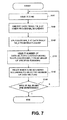
- FIG. 7 a flowchart is shown that shows the flow of a process including determining the BPIs of the zones, and resetting the zone boundaries at new boundaries shifted from the provisional boundaries.
- HDC/MPU 23 determines the BPIs sequentially from the innermost zone, or alternatively, from the outermost zone.
- FIG. 8 in accordance with embodiments of the present invention, an example to select zones sequentially from the outermost zone toward the innermost zone is next described.
- HDC/MPU 23 selects a zone (zone Zk in FIG. 8 ), and, at S 142 , identifies the ceiling limit BPI_T, which is a reference value, of the innermost data track, which is the data track on the inner boundary, Trk_ 0 in the zone.
- HDC/MPU 23 has determined the relationship between the reference value BPI_T and the radial position (refer to FIG. 6 ), and, at S 143 , calculates the reference value BPI_T of the innermost data track Trk_ 0 from the relationship.
- HDC/MPU 23 selects the number of data sectors corresponding to the calculated reference value BPI_T.
- HDC/MPU 23 has obtained beforehand a group of the numbers of data sectors, which are values each of which indicates the number of data sectors; and, each of the numbers is settable as the number of data sectors in a data track.
- HDC/MPU 23 selects an appropriate number of data sectors from the group according to the reference value BPI_T.
- the specified numbers of data sectors are selected so that the number of split sectors (refer to FIG. 11 ) is within a specified range with respect to the number of servo sectors which have been written.
- the specified data, including the numbers of data sectors, utilized for the zone format setting are stored in a nonvolatile memory on a circuit board.
- HDC/MPU 23 may obtain the numbers of data sectors from the host 51 . The details of selection of the number of data sectors according to the reference value BPI_T are subsequently described.
- HDC/MPU 23 subsequently, resets the inner boundary of the zone Zk at a new boundary from the provisional boundary according to the selected number of data sectors. If an inner zone exists after resetting the zone Zk (N-branch after S 146 ), at S 141 , HDC/MPU 23 selects the inner adjacent zone Zk+1 for the next setting process. If no inner zones exist (Y-branch after S 146 ), the BPI setting processes for all zones have been completed. HDC/MPU 23 may omit the resetting process for the innermost zone Z 0 . Selecting the number of data sectors and resetting the zone boundary according to the reference value BPI_T is next described specifically.
- HDC/MPU 23 calculates the reference value BPI_T to the innermost data track Trk_ 0 in the zone Zk.
- the number of data sectors indicating the BPI which is no more than and the closest to the calculated reference value BPI_T, is assumed to be 255.
- HDC/MPU 23 selects one of the two values. If it selects 254 as the number of data sectors to the zone Zk, HDC/MPU 23 , as illustrated in FIG. 9( b ), shifts inward the inner boundary of the zone Zk from the provisional boundary Trk_ 0 to a new boundary Trk_ 0 _N.
- the data track with the reference value BPI_T corresponding to the number of data sectors of 254 exists at a position closer to the inside diameter of the magnetic-recording disk than the data track Trk_ 0 .
- the number of data sectors in the inner zone Zk+1 adjacent to the zone Zk is smaller than that of the zone Zk.
- HDC/MPU 23 can identify the radial position, which gives the location of the data track, corresponding to the number of data sectors of 254, namely the data track whose BPI_T at the number of data sectors of 254 is larger than, and the closest to, the reference BPI_T.
- HDC/MPU 23 sets the identified data track as the innermost data track Trk_ 0 _N, which is at a zone boundary, in the zone Zk, which may provide for an optimized zone boundary in terms of the error rate and the capacity.
- HDC/MPU 23 may add a predetermined number of inner data tracks to the zone Zk.
- HDC/MPU 23 selects the number of data sectors as 258 for the zone Zk. Selecting a larger number, 258, for the zone Zk allows increasing the BPI of the zone Zk and, as a result, allows increasing the capacity of a recording surface. As shown in FIG. 9 ( c ), if HDC/MPU 23 selects the number of data sectors of 258 for the zone Zk, HDC/MPU 23 shifts outward the inner boundary of the zone Zk from the provisional boundary Trk_ 0 to a new boundary Trk_ 0 _N.
- the number of data sectors corresponding to the reference value BPI_T is 255.
- the error rate is larger than the one at the reference value BPI_T.
- HDC/MPU 23 shifts the inner boundary of the zone Zk outward so that the error rate of each data track in the zone Zk is smaller than the error rate of each data track at the reference value BPI_T.
- HDC/MPU 23 has the relationship between the radial position and the reference BPI_T.
- HDC/MPU 23 can identify the radial position, which gives the location of the data track, corresponding to the number of data sectors of 258, namely the data track whose BPI_T at the number of data sectors of 258 is larger than, and the closest to, the reference BPI_T.
- HDC/MPU 23 sets the identified data track as the innermost data track Trk_ 0 _N, which is at the zone boundary, in the zone Zk.
- HDC/MPU 23 may provide an optimized zone boundary in terms of the error rate and the capacity.
- HDC/MPU 23 may remove a predetermined number of inner data tracks from the zone Zk.
- HDC/MPU 23 may select the number of data sectors so that a zone boundary shifts inward, or alternatively, outward, depending on the circumstances. However, in a configuration for another embodiment of the present invention, HDC/MPU 23 chooses either the larger number, or alternatively, the smaller number, with reference to the relationship between the number of data sectors at the provisional boundary and the registered specific numbers.
- HDC/MPU 23 chooses the specified number, which is 254 in the above-described example, closest to the number of data sectors at the provisional boundary, which is 255 in the above-described example. If the difference from the larger value and the difference from the smaller value are the same, HDC/MPU 23 may choose either.
- the subsequent zone boundary resetting method is the same as the above description. In this way, in accordance with embodiments of the present invention, selecting an appropriate specified number of data sectors with reference to the relationship between the number of data sectors calculated at a provisional boundary and the specified numbers of data sectors allows increasing the data capacity of the recording surface.
- HDC/MPU 23 calculates the number of data sectors corresponding to the reference value BPI_T. In this calculation, HDC/MPU 23 in an embodiment of the present invention corrects variations in the gap between the servo sector and the data sector.
- FIG. 10 a drawing is shown that schematically illustrates a gap between a servo sector and a data sector.
- the gap varies in different data tracks. If the gap is large, the data sector length is shortened to increase the BPI, in order to contain a specified number of data sectors between servo sectors. Therefore, even if the same number of data sectors is contained at the same radial position, the BPI at the data track varies with the gap.
- HDC/MPU 23 determines the gap by measurement, and calculates the number of data sectors by use of the gap.
- HDC/MPU 23 calculates the number of data sectors corresponding to the reference value BPI_T of a target data track after measuring the gap in the target data track. For example, HDC/MPU 23 can calculate the value of the gap from a measured value of time between a servo address mark in a servo sector and a data address mark in a data sector. The servo address mark is data providing the reference timing in reading of the servo sector. In an embodiment of the present invention, HDC/MPU 23 measures all gaps in the target data track and uses the average in calculation of the number of data sectors.
- HDC/MPU 23 starts the BPI setting process for a zone after measuring gaps in data tracks selected from a recording surface.
- HDC/MPU 23 applies a modeling function to measured gap values to calculate a function, which provides a formula, indicating the relationship between the radial position, which gives the location of the data track, and the gap.
- the gap calculated with the formula is used.
- correcting variations in gaps with the radial position in the calculation of the number of data tracks in this way provides more precise BPI setting.
- the dimensional tolerance of a write element in the track width direction is large, a portion of an adjacent data track is erased. If the erasure amount of an adjacent data track is large, the error rate gets worse. Thus, if the dimensional tolerance of a write element in the track width direction is large, the BPI larger than a specified value is set so that the error rate is no more than a specified rate regardless of the data erasure.
- HDC/MPU 23 writes data for measurement on a track for error rate measurement in zones selected from a plurality of zones defined by provisional boundaries. Subsequently, HDC/MPU 23 writes data on either one of, or both of, inner and outer adjacent tracks of the track for error rate measurement, and then measures the error rate. HDC/MPU 23 determines the BPI with the measured error rates. In accordance with an embodiment of the present invention, the BPI setting according to the error rate in measuring the effect on an adjacent track provides a more appropriate BPI setting.
- embodiments of the present invention have been described by way of examples; but, embodiments of the present invention are not limited to the above-described examples, as embodiments of the present invention can, of course, be modified in various ways within the spirit and scope of embodiments of the present invention.
- embodiments of the present invention can be applied to disk drives with data-storage disks other than magnetic-recording disks, such as: optical disks, and magneto-optical disks.
- a HDD may select a value to match the number of data sectors calculated with reference to a specified BPI from a specified group of numbers, and reset a zone boundary position according to the value selected to match the number of data sectors calculated with reference to the specified BPI from the specified group of numbers.
Landscapes
- Engineering & Computer Science (AREA)
- Signal Processing (AREA)
- Signal Processing For Digital Recording And Reproducing (AREA)
Abstract
Description
Claims (18)
Applications Claiming Priority (2)
| Application Number | Priority Date | Filing Date | Title |
|---|---|---|---|
| JP2008320331A JP2010146615A (en) | 2008-12-16 | 2008-12-16 | Zone format setting method for disk storing data and disk drive |
| JP2008-320331 | 2008-12-16 |
Publications (2)
| Publication Number | Publication Date |
|---|---|
| US20110085259A1 US20110085259A1 (en) | 2011-04-14 |
| US8098448B2 true US8098448B2 (en) | 2012-01-17 |
Family
ID=42566898
Family Applications (1)
| Application Number | Title | Priority Date | Filing Date |
|---|---|---|---|
| US12/639,926 Expired - Fee Related US8098448B2 (en) | 2008-12-16 | 2009-12-16 | Method for setting zone format of a disk for storing data and disk drive |
Country Status (2)
| Country | Link |
|---|---|
| US (1) | US8098448B2 (en) |
| JP (1) | JP2010146615A (en) |
Families Citing this family (1)
| Publication number | Priority date | Publication date | Assignee | Title |
|---|---|---|---|---|
| CN109426615B (en) * | 2017-09-01 | 2022-01-28 | 深圳市源伞新科技有限公司 | Inter-process null pointer dereference detection method, system, device, and medium |
Citations (6)
| Publication number | Priority date | Publication date | Assignee | Title |
|---|---|---|---|---|
| JPH0512807A (en) | 1991-07-03 | 1993-01-22 | Hitachi Ltd | Disk device |
| JPH0721504A (en) | 1993-06-30 | 1995-01-24 | Nec Corp | Method and device for equal error rate recording |
| JPH10143811A (en) | 1996-11-12 | 1998-05-29 | Nec Ibaraki Ltd | Method of setting write frequency for magnetic recording device |
| JP2000123492A (en) | 1998-10-13 | 2000-04-28 | Internatl Business Mach Corp <Ibm> | Disk type recording medium, manufacturing method for disk type recording medium, recording and reproducing method, and disk drive device |
| US20060082918A1 (en) | 2004-10-15 | 2006-04-20 | Fujitsu Limited | Information storage apparatus, and control method and program for the same |
| US7317587B2 (en) * | 2002-12-12 | 2008-01-08 | Fujitsu Limited | Magnetic disk devices with data recording areas set separately for each device |
Family Cites Families (3)
| Publication number | Priority date | Publication date | Assignee | Title |
|---|---|---|---|---|
| JPH10154377A (en) * | 1996-11-22 | 1998-06-09 | Toshiba Corp | Disk and Cylinder Number Assignment Method by Zone for the Disk |
| JP2006164448A (en) * | 2004-12-09 | 2006-06-22 | Hitachi Global Storage Technologies Netherlands Bv | Disk device and control method thereof |
| JP2007213685A (en) * | 2006-02-08 | 2007-08-23 | Fujitsu Ltd | Disk device, disk formatting method and disk formatting device |
-
2008
- 2008-12-16 JP JP2008320331A patent/JP2010146615A/en active Pending
-
2009
- 2009-12-16 US US12/639,926 patent/US8098448B2/en not_active Expired - Fee Related
Patent Citations (7)
| Publication number | Priority date | Publication date | Assignee | Title |
|---|---|---|---|---|
| JPH0512807A (en) | 1991-07-03 | 1993-01-22 | Hitachi Ltd | Disk device |
| JPH0721504A (en) | 1993-06-30 | 1995-01-24 | Nec Corp | Method and device for equal error rate recording |
| JPH10143811A (en) | 1996-11-12 | 1998-05-29 | Nec Ibaraki Ltd | Method of setting write frequency for magnetic recording device |
| JP2000123492A (en) | 1998-10-13 | 2000-04-28 | Internatl Business Mach Corp <Ibm> | Disk type recording medium, manufacturing method for disk type recording medium, recording and reproducing method, and disk drive device |
| US7317587B2 (en) * | 2002-12-12 | 2008-01-08 | Fujitsu Limited | Magnetic disk devices with data recording areas set separately for each device |
| US20060082918A1 (en) | 2004-10-15 | 2006-04-20 | Fujitsu Limited | Information storage apparatus, and control method and program for the same |
| US7463438B2 (en) * | 2004-10-15 | 2008-12-09 | Fujitsu Limited | Information storage apparatus, and control method and program for the same |
Also Published As
| Publication number | Publication date |
|---|---|
| US20110085259A1 (en) | 2011-04-14 |
| JP2010146615A (en) | 2010-07-01 |
Similar Documents
| Publication | Publication Date | Title |
|---|---|---|
| US7595955B2 (en) | Disk drive device and method for error recovery procedure therefor | |
| US6754030B2 (en) | Optimal reader-to-writer offset measurement of a head in a disc drive for reduced track misregistration | |
| US7706096B2 (en) | Disk drive device manufacturing method thereof, and method for specifying data track pitch for the disk drive device | |
| JP5264630B2 (en) | Magnetic disk drive and data rewrite method | |
| US6873488B2 (en) | Enhanced MR offset with dynamic tuning range | |
| US20060018051A9 (en) | Vertical track zoning for disk drives | |
| US8131920B2 (en) | Method and system for dynamically allocating read and write sequence randomizer | |
| CN112420080B (en) | Magnetic disk device | |
| US9070411B1 (en) | Writable servo overlap zones | |
| CN100353448C (en) | Data recording/reproducing device, data recording/reproducing method, program, and recording medium | |
| JP2003249044A (en) | Magnetic disk drive system | |
| US7532426B2 (en) | Method for erase process on recording surface of disk and disk drive apparatus | |
| US8964322B2 (en) | Size adjustable inter-track interference cancellation | |
| US7349171B2 (en) | Method for measuring actuator velocity during self-servo-write | |
| US20180033457A1 (en) | Direct current magnetoresistive jog offset compensation | |
| US8098448B2 (en) | Method for setting zone format of a disk for storing data and disk drive | |
| US20090128943A1 (en) | Test method and manufaturing method of disk drive device in consideration of manufacturing efficiency | |
| KR100688556B1 (en) | Hard disk drive recording control method and a suitable hard disk drive and recording medium | |
| US7079347B2 (en) | Method and apparatus for providing a marker for adaptive formatting via a self-servowrite process | |
| JP2008146724A (en) | Disk storage device and servo test method | |
| US8009376B2 (en) | Disk drive device and method for determining data track format of the disk drive device | |
| US12211529B1 (en) | Fast characterization of media-noise-induced repeatable runout | |
| JP2007115324A (en) | Disk unit | |
| JP2009093756A (en) | Disk drive device and method of manufacturing disk drive device | |
| JP2007287252A (en) | Erase method for disc recording surface |
Legal Events
| Date | Code | Title | Description |
|---|---|---|---|
| FEPP | Fee payment procedure |
Free format text: PAYOR NUMBER ASSIGNED (ORIGINAL EVENT CODE: ASPN); ENTITY STATUS OF PATENT OWNER: LARGE ENTITY |
|
| AS | Assignment |
Owner name: HITACHI GLOBAL STORAGE TECHNOLOGIES, NETHERLANDS, Free format text: ASSIGNMENT OF ASSIGNORS INTEREST;ASSIGNORS:MAEDA, YOSHIHIKO;IKEDA, MASAOMI;KUWAMURA, NOBUHIRO;AND OTHERS;SIGNING DATES FROM 20091217 TO 20091224;REEL/FRAME:025556/0054 |
|
| STCF | Information on status: patent grant |
Free format text: PATENTED CASE |
|
| AS | Assignment |
Owner name: HGST, NETHERLANDS B.V., NETHERLANDS Free format text: CHANGE OF NAME;ASSIGNOR:HGST, NETHERLANDS B.V.;REEL/FRAME:029341/0777 Effective date: 20120723 Owner name: HGST NETHERLANDS B.V., NETHERLANDS Free format text: CHANGE OF NAME;ASSIGNOR:HITACHI GLOBAL STORAGE TECHNOLOGIES NETHERLANDS B.V.;REEL/FRAME:029341/0777 Effective date: 20120723 |
|
| FPAY | Fee payment |
Year of fee payment: 4 |
|
| AS | Assignment |
Owner name: WESTERN DIGITAL TECHNOLOGIES, INC., CALIFORNIA Free format text: ASSIGNMENT OF ASSIGNORS INTEREST;ASSIGNOR:HGST NETHERLANDS B.V.;REEL/FRAME:040826/0327 Effective date: 20160831 |
|
| FEPP | Fee payment procedure |
Free format text: MAINTENANCE FEE REMINDER MAILED (ORIGINAL EVENT CODE: REM.); ENTITY STATUS OF PATENT OWNER: LARGE ENTITY |
|
| LAPS | Lapse for failure to pay maintenance fees |
Free format text: PATENT EXPIRED FOR FAILURE TO PAY MAINTENANCE FEES (ORIGINAL EVENT CODE: EXP.); ENTITY STATUS OF PATENT OWNER: LARGE ENTITY |
|
| STCH | Information on status: patent discontinuation |
Free format text: PATENT EXPIRED DUE TO NONPAYMENT OF MAINTENANCE FEES UNDER 37 CFR 1.362 |
|
| FP | Lapsed due to failure to pay maintenance fee |
Effective date: 20200117 |