US8098301B2 - Zoom lens and image pickup apparatus - Google Patents
Zoom lens and image pickup apparatus Download PDFInfo
- Publication number
- US8098301B2 US8098301B2 US12/662,416 US66241610A US8098301B2 US 8098301 B2 US8098301 B2 US 8098301B2 US 66241610 A US66241610 A US 66241610A US 8098301 B2 US8098301 B2 US 8098301B2
- Authority
- US
- United States
- Prior art keywords
- lens
- lens group
- refractive power
- positive refractive
- zoom
- Prior art date
- Legal status (The legal status is an assumption and is not a legal conclusion. Google has not performed a legal analysis and makes no representation as to the accuracy of the status listed.)
- Expired - Fee Related, expires
Links
Images


Classifications
-
- G—PHYSICS
- G02—OPTICS
- G02B—OPTICAL ELEMENTS, SYSTEMS OR APPARATUS
- G02B15/00—Optical objectives with means for varying the magnification
- G02B15/14—Optical objectives with means for varying the magnification by axial movement of one or more lenses or groups of lenses relative to the image plane for continuously varying the equivalent focal length of the objective
- G02B15/144—Optical objectives with means for varying the magnification by axial movement of one or more lenses or groups of lenses relative to the image plane for continuously varying the equivalent focal length of the objective having four groups only
- G02B15/1445—Optical objectives with means for varying the magnification by axial movement of one or more lenses or groups of lenses relative to the image plane for continuously varying the equivalent focal length of the objective having four groups only the first group being negative
- G02B15/144513—Optical objectives with means for varying the magnification by axial movement of one or more lenses or groups of lenses relative to the image plane for continuously varying the equivalent focal length of the objective having four groups only the first group being negative arranged --++
Definitions
- the present invention relates to a zoom lens and an image pickup apparatus.
- the present invention relates to a zoom lens having a zoom ratio of about three and that is suitable for a camera-equipped mobile phone and a digital still camera including a solid-state image pickup device, and to an image pickup apparatus including the zoom lens.
- Image pickup apparatuses such as camera-equipped mobile phones or digital still cameras, using a solid-state image pickup device such as a charge coupled device (CCD) or a complementary metal-oxide semiconductor (CMOS) device, have become widespread. Reduction in the size and thickness of such an image pickup apparatus has been desired, and there has been an increasing demand for reduction in the length and depth of an image pickup lens included in the image pickup apparatus.
- CCD charge coupled device
- CMOS complementary metal-oxide semiconductor
- compact image pickup apparatuses such as camera-equipped mobile phones have been reduced in size and the number of pixels of image pickup devices included in the compact image pickup apparatuses have increased. Accordingly, high performance lenses compatible with high-pixel-count solid-state image pickup devices have been desired for use in the compact image pickup apparatuses.
- some zoom lenses include a lens group having a prism for bending a light path so as to reduce the size and thickness of the zoom lens along the optical axis of an incident light beam (see, for example, Japanese Unexamined Patent Application Publication No. 2004-354869 and No. 2008-33208).
- a zoom lens described in Japanese Unexamined Patent Application Publication No. 2004-354869 includes, in sequence from the object side to the image side, a first lens group having a positive refractive power, a second lens group having a negative refractive power, a third lens group having a positive refractive power, a fourth lens group having a positive refractive power, and a fifth lens group having a negative refractive power.
- a prism for bending a light path is disposed in the first lens group so as to reduce the thickness of the zoom lens, and high optical performance is obtained over the entire zooming range from the wide angle end to the telephoto end.
- the total optical length of this type of zoom lens is still long, and the reduction in size is still insufficient for use in a compact image pickup apparatus such as a camera-equipped mobile phone.
- the production cost is high, because a large number of lenses are used and the lenses are made of a glass material.
- a zoom lens described in Japanese Unexamined Patent Application Publication No. 2008-33208 includes, in sequence from the object side to the image side, a first lens group having a weak refractive power, a second lens group having a negative refractive power, a third lens group having a positive refractive power, and a fourth lens group having a positive refractive power.
- a prism for bending a light path is disposed in the first lens group so as to reduce the thickness of the zoom lens.
- a plurality of lenses used in the zoom lens are made of a resin material so as to reduce the production cost and to reduce the total optical length.
- the second lens group of this zoom lens is constituted by one lens having a negative refractive power, chromatic aberration, in particular, transverse chromatic aberration at the wide angle end and longitudinal chromatic aberration at the telephoto end are not sufficiently corrected. As a result, the performance of the zoom lens is insufficient to be used with a recent solid-state image pickup device having a high pixel count.
- a zoom lens and an image pickup apparatus having a simple structure and high optical performance compatible with an image pickup device having a high pixel count, having a stable performance that is not seriously affected when the ambient temperature changes, and having reduced production cost and reduced size and thickness.
- a zoom lens including a first lens group, a second lens group having a negative refractive power, a third lens group having a positive refractive power, and a fourth lens group having a positive refractive power, wherein zooming and correction of an imaging position during zooming are performed by moving at least one of the second lens group and the third lens group, wherein the first lens group includes, in sequence from the object side to the image side, a single lens having a negative refractive power, a prism for bending a light path, and a single lens having a positive refractive power and made of a resin material, wherein the second lens group includes, in sequence from the object side to the image side, one lens having a negative refractive power and made of a resin material and one lens having a positive refractive power and made of a resin material, and wherein the following conditional expressions f 12 /fw> 2.0, (1) f 2 /fw ⁇ 2.0, (2) ⁇ 2.0 ⁇ f 12
- the production cost is reduced by using the lenses made of a resin material, and deterioration of the optical performance due to variation in the ambient temperature is suppressed.
- the third lens group include at least one lens having a positive refractive power and at least one lens having a negative refractive power, the at least one lens having a positive refractive power be disposed nearest to an object in the third lens group, the at least one lens having a negative refractive power be disposed nearest to an image in the third lens group, and the following conditional expression 0.9 ⁇ 3 W ⁇ 3 T ⁇ 1.1 (5) be satisfied, where ⁇ 3 W is a lateral magnification of the third lens group at the wide angle end with respect to an object at infinity, and ⁇ 3 T is a lateral magnification of the third lens group at the telephoto end with respect to an object at infinity.
- the zoom lens has the structure described above and satisfies the conditional expression (5), the position of the principal point of the third lens group becomes close to the second lens group and the magnification of the third lens group is limited.
- the zoom lens satisfy the following conditional expression 1.7 ⁇ f 22 /fw ⁇ 3.1, (6) where f 22 is a focal length of the lens having a positive refractive power included in the second lens group.
- the zoom lens satisfies the conditional expression (6), the refractive power of the lens having a positive refractive power included in the second lens group and made of a resin material is limited and the refractive power of the lenses included in the second lens group increases, whereby correction of transverse chromatic aberration, in particular, correction of coma and field curvature is appropriately performed.
- the lens having a negative refractive power included in the second lens group and the lens having a positive refractive power included in the second lens group be cemented to each other.
- the lens having a negative refractive power included in the second lens group and the lens having a positive refractive power included in the second lens group are cemented to each other, the sensitivity in a deflected state is reduced.
- an image pickup apparatus including a zoom lens and an image pickup device that converts an optical image formed by the zoom lens to an electrical signal
- the zoom lens includes, in sequence from the object side to the image side, a first lens group, a second lens group having a negative refractive power, a third lens group having a positive refractive power, and a fourth lens group having a positive refractive power, wherein zooming and correction of an imaging position during zooming are performed by moving at least one of the second lens group and the third lens group
- the first lens group includes, in sequence from the object side to the image side, a single lens having a negative refractive power, a prism for bending a light path, and a single lens having a positive refractive power and made of a resin material
- the second lens group includes, in sequence from the object side to the image side, one lens having a negative refractive power and made of a resin material and one lens having a positive refractive power and made of
- the production cost is reduced by using the lenses made of a resin material, and deterioration of the optical performance due to variation in the ambient temperature is suppressed.
- a zoom lens according to an embodiment of the present invention includes a first lens group, a second lens group having a negative refractive power, a third lens group having a positive refractive power, and a fourth lens group having a positive refractive power, wherein zooming and correction of an imaging position during zooming are performed by moving at least one of the second lens group and the third lens group, wherein the first lens group includes, in sequence from the object side to the image side, a single lens having a negative refractive power, a prism for bending a light path, and a single lens having a positive refractive power and made of a resin material, wherein the second lens group includes, in sequence from the object side to the image side, one lens having a negative refractive power and made of a resin material and one lens having a positive refractive power and made of a resin material, and wherein the following conditional expressions f 12 /fw> 2.0, (1) f 2 /fw ⁇ 2.0, (2) ⁇ 2.0 ⁇ f 12 /f 2
- the zoom lens has high optical performance compatible with a large-pixel-count image pickup device, and the production cost, the size, and the thickness of the zoom lens can be reduced.
- the third lens group includes at least one lens having a positive refractive power and at least one lens having a negative refractive power, the at least one lens having a positive refractive power is disposed nearest to an object in the third lens group, the at least one lens having a negative refractive power is disposed nearest to an image in the third lens group, and the following conditional expression 0.9 ⁇ 3 W ⁇ 3 T ⁇ 1.1 (5) is satisfied, where ⁇ 3 W is a lateral magnification of the third lens group at the wide angle end with respect to an object at infinity, and ⁇ 3 T is a lateral magnification of the third lens group at the telephoto end with respect to an object at infinity.
- a zoom lens according to an embodiment of the present invention satisfies the following conditional expression 1.7 ⁇ f 22 /fw ⁇ 3.1, (6) where f 22 is a focal length of the lens having a positive refractive power included in the second lens group.
- the lens having a negative refractive power included in the second lens group and the lens having a positive refractive power included in the second lens group are cemented to each other.
- the sensitivity in a deflected state can be reduced, and the mass productivity can be increased.
- An image pickup apparatus includes a zoom lens, and an image pickup device that converts an optical image formed by the zoom lens to an electrical signal
- the zoom lens includes, in sequence from the object side to the image side, a first lens group, a second lens group having a negative refractive power, a third lens group having a positive refractive power, and a fourth lens group having a positive refractive power, wherein zooming and correction of an imaging position during zooming are performed by moving at least one of the second lens group and the third lens group
- the first lens group includes, in sequence from the object side to the image side, a single lens having a negative refractive power, a prism for bending a light path, and a single lens having a positive refractive power and made of a resin material
- the second lens group includes, in sequence from the object side to the image side, one lens having a negative refractive power and made of a resin material and one lens having a positive refractive power and made of a resin
- the image pickup apparatus has high optical performance compatible with a large-pixel-number image pickup device, and the size and the thickness of the image pickup apparatus can be reduced while suppressing increase in production cost.
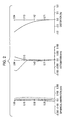
- FIG. 1 illustrates the lens structure of a zoom lens according to a first embodiment of the present invention
- FIG. 2 is an aberration diagram of a numerical example to which specific values are assigned to the first embodiment, illustrating spherical aberration, astigmatism, and distortion in the wide angle end state;
- FIG. 3 is a diagram illustrating spherical aberration, astigmatism, and distortion in the medium focal length state
- FIG. 4 is a diagram illustrating spherical aberration, astigmatism, and distortion in the telephoto end state
- FIG. 5 illustrates the lens structure of a zoom lens according to a second embodiment of the present invention
- FIG. 6 is an aberration diagram of a numerical example to which specific values are assigned to the second embodiment, illustrating spherical aberration, astigmatism, and distortion in the wide angle end state;
- FIG. 7 is a diagram illustrating spherical aberration, astigmatism, and distortion in the medium focal length state
- FIG. 8 is a diagram illustrating spherical aberration, astigmatism, and distortion in the telephoto end state
- FIG. 9 illustrates the lens structure of a zoom lens according to a third embodiment of the present invention.
- FIG. 10 is an aberration diagram of a numerical example to which specific values are assigned to the third embodiment, illustrating spherical aberration, astigmatism, and distortion in the wide angle end state;
- FIG. 11 is a diagram illustrating spherical aberration, astigmatism, and distortion in the medium focal length state
- FIG. 12 is a diagram illustrating spherical aberration, astigmatism, and distortion in the telephoto end state
- FIG. 13 illustrates the lens structure of a zoom lens according to a fourth embodiment of the present invention.
- FIG. 14 is an aberration diagram of a numerical example to which specific values are assigned to the fourth embodiment, illustrating spherical aberration, astigmatism, and distortion in the wide angle end state;
- FIG. 15 is a diagram illustrating spherical aberration, astigmatism, and distortion in the medium focal length state
- FIG. 16 is a diagram illustrating spherical aberration, astigmatism, and distortion in the telephoto end state.
- FIG. 17 is a block diagram of an image pickup apparatus according to an embodiment of the present invention.
- a zoom lens according to an embodiment of the present invention includes, in sequence from the object side to the image side, a first lens group, a second lens group having a negative refractive power, a third lens group having a positive refractive power, and a fourth lens group having a positive refractive power. Zooming and correction of the imaging position during zooming are performed by moving at least one of the second lens group and the third lens group.
- the zoom lens has such refractive power arrangement, the total optical length and the size of the zoom lens are reduced.
- the first lens group is fixed during zooming.
- a seal glass for protecting an image pickup device is disposed between the fourth lens group and the image surface.
- zooming and correction of the imaging position during zooming can be performed by moving the second and third lens groups, or by moving the second, third, and fourth lens groups.
- the first lens group of the zoom lens according to the embodiment of the present invention includes, in sequence from the object side to the image side, a single lens having a negative refractive power, a prism for bending a light path, and a single lens having a positive refractive, power and made of a resin material.
- the first lens group has this structure, movable lens groups are moved during zooming along the optical axis of the single lens having a positive refractive power included in the first lens group, whereby the thickness of the zoom lens along the optical axis of an incident light beam can be reduced.
- the second lens group of the zoom lens according to the embodiment of the present invention includes, in sequence from the object side to the image side, one lens having a negative refractive power and made of a resin material and one lens having a positive refractive power and made of a resin material.
- the second lens group has this structure and the zoom lens satisfies the conditional expressions (1) to (4) described below, high optical performance is secured, an increase in production cost is suppressed, and degradation of optical property due to variation in the ambient temperature can be suppressed.
- the second lens group includes one lens having a negative refractive power and one lens having a positive refractive power as described above, chromatic aberration, in particular, transverse chromatic aberration at the wide angle end and longitudinal chromatic aberration at the telephoto end are appropriately corrected.
- the zoom lens according to the embodiment of the present invention satisfies the following conditional expressions f 12 /fw> 2.0, (1) f 2 /fw ⁇ 2.0, (2) ⁇ 2.0 ⁇ f 12 /f 2 ⁇ 0.5, and (3) ⁇ d 21 ⁇ d 22>20, (4) where f 12 is the focal length of the single lens having a positive refractive power included in the first lens group, f 2 is the focal length of the second lens group, fw is the focal length of the total lens system at the wide angle end, ⁇ d 21 is the Abbe number of the lens having a negative refractive power included in the second lens group for the d-line, and ⁇ d 22 is the Abbe number of the lens having a positive refractive power included in the second lens group for the d-line.
- conditional expression (1) represents the ratio of the focal length of the single lens having a positive refractive power included in the first lens group to the focal length of the total lens system at the wide angle end, and limits the refractive power of the single lens having a positive refractive power included in the first lens group.
- the refractive power of the lens made of a resin material is too high. In this case, it is difficult to secure high optical performance, because the optical property (the index of refraction and the Abbe number) of a resin material varies comparatively widely.
- the zoom lens satisfies the conditional expression (1), high optical performance is secured even when a lens made of a resin material is used.
- the conditional expression (2) represents the ratio of the focal length of the second lens group to the focal length of the total lens system at the wide angle end, and limits the refractive power of the second lens group.
- the refractive power of the lens group made of a resin material is too high. In this case, it is difficult to secure high optical performance, because the optical property (the index of refraction and the Abbe number) of a resin material varies comparatively widely.
- the zoom lens satisfies the conditional expression (2), high optical performance is secured even when a lens made of a resin material is used.
- conditional expression (3) represents the ratio of the focal length of the single lens having a positive refractive power included in the first lens group to the focal length of the second lens group, and limits the balance of refractive power.
- conditional expression (3) If the conditional expression (3) is not satisfied, the balance of aberration correction is disturbed when the ambient temperature varies, so that the optical performance deteriorates and it becomes difficult to maintain high optical performance compatible with an image pickup device having a high pixel count.
- the zoom lens satisfies the conditional expression (3), high optical performance is maintained even when the single lens having a positive refractive power included in the first lens group and the lenses included in the second lens group are made of a resin material and the ambient temperature varies.
- the conditional expression (4) represents the difference between the Abbe number of the lens having a negative refractive power included in the second lens group for the d-line and the Abbe number of the lens having a positive refractive power included in the second lens group for the d-line, and specifies a condition for appropriately correcting chromatic aberration generated in the second lens group.
- the zoom lens satisfies the conditional expression (4), chromatic aberration generated in the second lens group, in particular, transverse chromatic aberration at the wide angle end and longitudinal chromatic aberration at the telephoto end are appropriately corrected, so that the optical performance can be improved.
- the production cost of the zoom lens according to the embodiment of the present invention can be reduced, because a lens disposed nearest to the image in the first lens group and two lenses in the second lens group are made of a resin material as described above.
- the lens disposed nearest to the image in the first lens group has a positive refractive power
- the second lens group has a negative refractive power.
- the ratio of the focal length of the lens disposed nearest to the image in the first lens group to the focal length of the second lens group is limited to a small value within the range of 0.5 to 2 as shown by the conditional expression (3).
- the lens disposed nearest to the image in the first lens group has a positive refractive power and the second lens group has a negative refractive power, and the ratio between the focal lengths thereof is limited to a small value, deterioration of the performance due to variation in the ambient temperature is suppressed. That is, variation in aberration, which is generated in one of the second lens group and the lens disposed nearest to the image in the first lens group owing to variation in the ambient temperature, is prevented from being generated in the other one of the lens and the lens group, whereby high optical performance is secured.
- the production cost of the zoom lens is reduced by using the lenses made of a resin material, and deterioration of the optical performance due to variation in the ambient temperature is suppressed, so that high optical performance can be secured.
- a lens disposed on the image side in the second lens group has a meniscus shape that is convex toward the object side and concave toward the image side. Therefore, distortion can be appropriately corrected.
- the third lens group include at least one lens having a positive refractive power and at least one lens having a negative refractive power.
- the at least one lens having a positive refractive power be disposed nearest to the object in the third lens group
- the at least one lens having a negative refractive power be disposed nearest to the image in the third lens group, and the following conditional expression 0.9 ⁇ 3 W ⁇ ⁇ 3 T ⁇ 1.1 (5) be satisfied, where ⁇ 3 W is the lateral magnification of the third lens group at the wide angle end with respect to an object at infinity, and ⁇ 3 T is a lateral-magnification of the third lens group at the telephoto end with respect to an object at infinity.
- the position of the principal point of the third lens group can be made close to the second lens group, whereby the total length of the zoom lens at the telephoto end, which determines the size of the zoom lens, can be reduced.
- conditional expression (5) represents the product of the lateral magnification of the third lens group at the wide angle end with respect to an object at infinity and the lateral magnification of the third lens group at the telephoto end with respect to an object at infinity, and limits the magnification of the third lens group.
- the lateral magnification of the third lens group is set to be about ⁇ 1 at an intermediate focal position between the wide angle end and the telephoto end, so that the total length of the optical system is limited and the size of the zoom lens is reduced.
- a zoom lens according to an embodiment of the present invention satisfy the following conditional expression 1.7 ⁇ f 22 /fw ⁇ 3.1, (6) where f 22 is the focal length of the lens having a positive refractive power included in the second lens group.
- the refractive power of the lens having a positive refractive power included in the second lens group is to be set in an appropriate range in order to suppress optical aberration that is generated in the second lens group and reduce the size of the lens system.
- conditional expression (6) represents the ratio of the focal length of the lens having a positive refractive power included the second lens group to the focal length of the total lens system at the wide angle end, and limits the refractive power of the lens having a positive refractive power included in the second lens group and made of a resin material.
- the size of the zoom lens may be reduced relatively easily.
- the lens having a negative refractive power included in the second lens group and the lens having a positive refractive power included in the second lens group be cemented to each other.
- the lens having a negative refractive power included in the second lens group and the lens having a positive refractive power included in the second lens group are cemented to each other, sensitivity in a deflected state can be reduced and mass productivity can be increased.
- the shapes of the surfaces facing each other can be flexibly designed and aberration can be appropriately corrected.
- focusing on an object in a close range can be performed by moving the second lens group or the fourth lens group along the optical axis.
- an image on the image surface can be moved and motion blur can be optically corrected by moving a part of or all of the lens groups in a direction that is not parallel to the optical axis.
- f denotes the focal length
- Fno denotes the F. number
- 2 ⁇ denotes the angle of view
- Si denotes the surface number
- Ri denotes the radius of curvature
- di denotes the inter-surface distance between the i-th surface and the (i+1)-th surface along the optical axis
- ni denotes the index of refraction
- ⁇ i denotes the Abbe number.
- ASP represents that the surface is aspheric
- ⁇ represents that the surface is flat.
- variable represents that the inter-surface distance is variable.
- K denotes the conic constant
- A”, “B”, “C”, and “D” respectively denote the 4th order, the 6th order, the 8th order, and the 10th order aspheric coefficients.
- the aspheric shape is defined by the following expression (1), where “Z” is the distance from the vertex of the lens surface along the optical axis (aspheric depth), “Y” is the height in the direction perpendicular to the optical axis (image height), “R” is the paraxial curvature at the vertex of the lens (the reciprocal of the radius of curvature), “K” is the conic constant, and “A”, “B”, “C”, and “D” are respectively the 4th order, the 6th order, the 8th order, and the 10th order aspheric coefficients.
- FIG. 1 illustrates the lens structure of a zoom lens 1 according to a first embodiment of the present invention.
- the zoom lens 1 includes eight lenses and one prism.
- the zoom lens 1 includes, in sequence from the object side to the image side, a first lens group GR 1 having a weak negative refractive power, a second lens group GR 2 having a negative refractive power, a third lens group GR 3 having a positive refractive power, and a fourth lens group GR 4 having a positive refractive power.
- zooming and correction of the imaging position during zooming are performed by moving the second lens group GR 2 toward the image side along a convex path and moving the third lens group GR 3 monotonously toward the object side.
- the first lens group GR 1 includes, in sequence from the object side to the image side, a negative lens G 1 having a meniscus shape with a convex surface facing the object side, a prism G 2 for bending a light path, and a positive lens G 3 having a biconvex shape.
- the negative lens G 1 and the prism G 2 are made of a glass material, and the positive lens G 3 is made of a resin material.
- the second lens group GR 2 includes a cemented lens constituted by a negative lens G 4 having a biconcave shape and a positive lens G 5 having a meniscus shape with a concave surface facing the image side.
- the negative lens G 4 and the positive lens G 5 are made of a resin material.
- the third lens group GR 3 includes, in sequence from the object side to the image side, a positive lens G 6 having a biconvex shape, and a cemented lens constituted by a positive lens G 7 having a biconvex shape and a negative lens G 8 having a biconcave shape.
- the positive lens G 6 , the positive lens G 7 , and the negative lens G 8 are made of a glass material.
- the fourth lens group GR 4 includes a positive lens G 9 having a meniscus shape with a concave surface facing the object side.
- the positive lens G 9 is made of a resin material.
- a seal glass SG is disposed between the fourth lens group GR 4 and an image surface IMG.
- Table 1 illustrates the lens data of a first numerical example in which specific values are assigned to the zoom lens 1 of the first embodiment.
- both surfaces (R 5 , R 6 ) of the positive lens G 3 in the first lens group GR 1 , both surfaces (R 10 , R 11 ) of the positive lens G 6 in the third lens group GR 3 , and both surfaces (R 15 , R 16 ) of the positive lens G 9 in the fourth lens group GR 4 are aspheric.
- Table 2 illustrates the 4th order, the 6th order, the 8th order, and the 10th order aspheric coefficients A, B, C, and D and the conic constant K of the aspheric surfaces in the first numerical example.
- E-i represents an exponential expression with base 10 , that is, “10 ⁇ i ”.
- base 10 that is, “10 ⁇ i ”.
- 0.12345E-05 represents “0.12345 ⁇ 10 ⁇ 5 ”.
- the inter-surface distance d 6 between the first lens group GR 1 and the second lens group GR 2 , the inter-surface distance d 9 between the second lens group GR 2 and the third lens group GR 3 , and the inter-surface distance d 14 between the third lens group GR 3 and the fourth lens group GR 4 change.
- Table 3 illustrates the inter-surface distances in the first numerical example in the wide angle end state, the medium focal length state, and the telephoto end state, as well as the F number Fno and the angle of view 2 ⁇ .
- FIGS. 2 to 4 illustrate aberration diagrams of the first numerical example focused on infinity, in which FIG. 2 is an aberration diagram for the wide angle end state, FIG. 3 is an aberration diagram for the medium focal length state, and FIG. 4 is an aberration diagram for the telephoto end state.
- the data for the d-line is illustrated with a solid line
- the data for the g-line is illustrated with an alternate long and short dash line
- the data for C-line is illustrated with a broken line.
- the data for the sagittal image surface is illustrated with a solid line
- the data for the meridional image surface is illustrated with a broken line.
- FIG. 5 illustrates the lens structure of a zoom lens 2 according to a second embodiment of the present invention.
- the zoom lens 2 includes eight lenses and one prism.
- the zoom lens 2 includes, in sequence from the object side to the image side, a first lens group GR 1 having a weak negative refractive power, a second lens group GR 2 having a negative refractive power, a third lens group GR 3 having a positive refractive power, and a fourth lens group GR 4 having a positive refractive power.
- zooming and correction of the imaging position during zooming are performed by moving the second lens group GR 2 toward the image side along a convex path and moving the third lens group GR 3 monotonously toward the object side.
- the first lens group GR 1 includes, in sequence from the object side to the image side, a negative lens G 1 having a biconcave shape, a prism G 2 for bending a light path, and a positive lens G 3 having a biconvex shape.
- the negative lens G 1 and the prism G 2 are made of a glass material, and the positive lens G 3 is made of a resin material.
- the second lens group GR 2 includes a cemented lens constituted by a negative lens G 4 having a biconcave shape and a positive lens G 5 having a meniscus shape with a concave surface facing the image side.
- the negative lens G 4 and the positive lens G 5 are made of a resin material.
- the third lens group GR 3 includes, in sequence from the object side to the image side, a positive lens G 6 having a biconvex shape, and a cemented lens constituted by a positive lens G 7 having a biconvex shape and a negative lens G 8 having a biconcave shape.
- the positive lens G 6 , the positive lens G 7 , and the negative lens G 8 are made of a glass material.
- the fourth lens group GR 4 includes a positive lens G 9 having a meniscus shape with a concave surface facing the object side.
- the positive lens G 9 is made of a resin material.
- a seal glass SG is disposed between the fourth lens group GR 4 and an image surface IMG.
- Table 4 illustrates the lens data of a second numerical example in which specific values are assigned to the zoom lens 2 of the second embodiment.
- both surfaces (R 5 , R 6 ) of the positive lens G 3 in the first lens group GR 1 , both surfaces (R 10 , R 11 ) of the positive lens G 6 in the third lens group GR 3 , and both surfaces (R 15 , R 16 ) of the positive lens G 9 in the fourth lens group GR 4 are aspheric.
- Table 5 illustrates the 4th order, the 6th order, the 8th order, and the 10th order aspheric coefficients A, B, C, and D and the conic constant K of the aspheric surfaces in the second numerical example.
- the inter-surface distance d 6 between the first lens group GR 1 and the second lens group GR 2 , the inter-surface distance d 9 between the second lens group GR 2 and the third lens group GR 3 , and the inter-surface distance d 14 between the third lens group GR 3 and the fourth lens group GR 4 change.
- Table 6 illustrates the inter-surface distances in the second numerical example in the wide angle end state, the medium focal length state, and the telephoto end state, as well as the F number Fno and the angle of view 2 ⁇ .
- FIGS. 6 to 8 illustrate aberration diagrams of the second numerical example focused on infinity, in which FIG. 6 is an aberration diagram for the wide angle end state, FIG. 7 is an aberration diagram for the medium focal length state, and FIG. 8 is an aberration diagram for the telephoto end state.
- the data for the d-line is illustrated with a solid line
- the data for the g-line is illustrated with an alternate long and short dash line
- the data for C-line is illustrated with a broken line.
- the data for the sagittal image surface is illustrated with a solid line
- the data for the meridional image surface is illustrated with a broken line.
- FIG. 9 illustrates the lens structure of a zoom lens 3 according to a third embodiment of the present invention.
- the zoom lens 3 includes eight lenses and one prism.
- the zoom lens 3 includes, in sequence from the object side to the image side, a first lens group GR 1 having a weak negative refractive power, a second lens group GR 2 having a negative refractive power, a third lens group GR 3 having a positive refractive power, and a fourth lens group GR 4 having a positive refractive power.
- zooming and correction of the imaging position during zooming are performed by moving the second lens group GR 2 toward the image side along a convex path, moving the third lens group GR 3 monotonously toward the object side, and moving the fourth lens group GR 4 monotonously toward the image side.
- the first lens group GR 1 includes, in sequence from the object side to the image side, a negative lens G 1 having a piano-concave shape, a prism G 2 for bending a light path, and a positive lens G 3 having a biconvex shape.
- the negative lens G 1 and the prism G 2 are made of a glass material, and the positive lens G 3 is made of a resin material.
- the second lens group GR 2 includes a cemented lens constituted by a negative lens G 4 having a biconcave shape and a positive lens G 5 having a meniscus shape with a concave surface facing the image side.
- the negative lens G 4 and the positive lens G 5 are made of a resin material.
- the third lens group GR 3 includes, in sequence from the object side to the image side, a positive lens G 6 having a biconvex shape, and a cemented lens constituted by a positive lens G 7 having a biconvex shape and a negative lens G 8 having a biconcave shape.
- the positive lens G 6 , the positive lens G 7 , and the negative lens G 8 are made of a glass material.
- the fourth lens group GR 4 includes a positive lens G 9 having a meniscus shape with a concave surface facing the object side.
- the positive lens G 9 is made of a resin material.
- a seal glass SG is disposed between the fourth lens group GR 4 and an image surface IMG.
- Table 7 illustrates the lens data of a third numerical example in which specific values are assigned to the zoom lens 3 of the third embodiment.
- both surfaces (R 5 , R 6 ) of the positive lens G 3 in the first lens group GR 1 , both surfaces (R 10 , R 11 ) of the positive lens G 6 in the third lens group GR 3 , and both surfaces (R 15 , R 16 ) of the positive lens G 9 in the fourth lens group GR 4 are aspheric.
- Table 8 illustrates the 4th order, the 6th order, the 8th order, and the 10th order aspheric coefficients A, B, C, and D and the conic constant K of the aspheric surfaces in the first numerical example.
- the inter-surface distance d 6 between the first lens group GR 1 and the second lens group GR 2 , the inter-surface distance d 9 between the second lens group GR 2 and the third lens group GR 3 , the inter-surface distance d 14 between the third lens group GR 3 and the fourth lens group GR 4 , and the inter-surface distance d 16 between the fourth lens group GR 4 and the seal glass SG change.
- Table 9 illustrates the inter-surface distances in the third numerical example in the wide angle end state, the medium focal length state, and the telephoto end state, as well as the F number Fno and the angle of view 2 ⁇ .
- FIGS. 10 to 12 illustrate aberration diagrams of the third numerical example focused on infinity, in which FIG. 10 is an aberration diagram for the wide angle end state, FIG. 11 is an aberration diagram for the medium focal length state, and FIG. 12 is an aberration diagram for the telephoto end state.
- the data for the d-line is illustrated with a solid line
- the data for the g-line is illustrated with an alternate long and short dash line
- the data for C-line is illustrated with a broken line.
- the data for the sagittal image surface is illustrated with a solid line
- the data for the meridional image surface is illustrated with a broken line.
- FIG. 13 illustrates the lens structure of a zoom lens 4 according to a fourth embodiment of the present invention.
- the zoom lens 4 includes eight lenses and one prism.
- the zoom lens 4 includes, in sequence from the object side to the image side, a first lens group GR 1 having a weak negative refractive power, a second lens group GR 2 having a negative refractive power, a third lens group GR 3 having a positive refractive power, and a fourth lens group GR 4 having a positive refractive power.
- zooming and correction of the imaging position during zooming are performed by moving the second lens group GR 2 toward the image side on a convex path and moving the third lens group GR 3 monotonously toward the object side.
- the first lens group GR 1 includes, in sequence from the object side to the image side, a negative lens G 1 having a biconcave shape, a prism G 2 for bending a light path, and a positive lens G 3 having a meniscus shape with a concave surface facing the object side.
- the negative lens G 1 and the prism G 2 are made of a glass material, and the positive lens G 3 is made of a resin material.
- the second lens group GR 2 includes a negative lens G 4 having a biconcave shape and a positive lens G 5 having a meniscus shape with a concave surface facing the image side.
- the negative lens G 4 and the positive lens G 5 are made of a resin material.
- the third lens group GR 3 includes, in sequence from the object side to the image side, a positive lens G 6 having a biconvex shape, and a cemented lens constituted by a positive lens G 7 having a biconvex shape and a negative lens G 8 having a biconcave shape.
- the positive lens G 6 , the positive lens G 7 , and the negative lens G 8 are made of a glass material.
- the fourth lens group GR 4 includes a positive lens G 9 having a meniscus shape with a concave surface facing the object side.
- the positive lens G 9 is made of a resin material.
- a seal glass SG is disposed between the fourth lens group GR 4 and an image surface IMG.
- Table 10 illustrates the lens data of a fourth numerical example in which specific values are assigned to the zoom lens 4 of the fourth embodiment.
- both surfaces (R 5 , R 6 ) of the positive lens G 3 in the first lens group GR 1 , a surface (R 9 ) of the positive lens G 5 in the second lens group GR 2 facing the object side, both surfaces (R 11 , R 12 ) of the positive lens G 6 in the third lens group GR 3 , and both surfaces (R 16 , R 17 ) of the positive lens G 9 in the fourth lens group GR 4 are aspheric.
- Table 11 illustrates the 4th order, the 6th order, the 8th order, and the 10th order aspheric coefficients A, B, C, and D and the conic constant K of the aspheric surfaces in the fourth numerical example.
- the inter-surface distance d 6 between the first lens group GR 1 and the second lens group GR 2 , the inter-surface distance d 10 between the second lens group GR 2 and the third lens group GR 3 , and the inter-surface distance d 15 between the third lens group GR 3 and the fourth lens group GR 4 change.
- Table 12 illustrates the inter-surface distances in the first numerical example in the wide angle end state, the medium focal length state, and the telephoto end state, as well as the F number Fno and the angle of view 2 ⁇ .
- FIGS. 14 to 16 illustrate aberration diagrams of the fourth numerical example focused on infinity, in which FIG. 14 is an aberration diagram for the wide angle end state, FIG. 15 is an aberration diagram for the medium focal length state, and FIG. 16 is an aberration diagram for the telephoto end state.
- the data for the d-line is illustrated with a solid line
- the data for the g-line is illustrated with an alternate long and short dash line
- the data for C-line is illustrated with a broken line.
- the data for the sagittal image surface is illustrated with a solid line
- the data for the meridional image surface is illustrated with a broken line.
- Table 13 illustrates values of the conditional expressions (1) to (6) for the zoom lenses 1 to 4 .
- the image pickup apparatus includes a zoom lens and an image pickup device that converts an optical image formed by the zoom lens to an electrical signal.
- the zoom lens includes, in sequence from the object side to the image side, a first lens group, a second lens group having a negative refractive power, a third lens group having a positive refractive power, and a fourth lens group having a positive refractive power. Zooming and correction of the imaging position during zooming are performed by moving at least one of the second lens group and the third lens group.
- the zoom lens has such refractive power arrangement, the total optical length and the size of the image pickup apparatus are reduced.
- the first lens group is fixed during zooming.
- a seal glass for protecting an image pickup device is disposed between the fourth lens group and the image surface.
- zooming and correction of the imaging position during zooming can be performed by moving the second and third lens groups, or by moving the second, third, and fourth lens groups.
- the first lens group includes, in sequence from the object side to the image side, a single lens having a negative refractive power, a prism for bending a light path, and a single lens having a positive refractive power and made of a resin material.
- the first lens group has this structure, movable lens groups are moved during zooming along the optical axis of the single lens having a positive refractive power included in the first lens group, whereby the thickness of the zoom lens along the optical axis of an incident light beam can be reduced.
- the second lens group includes, in sequence from the object side to the image side, one lens having a negative refractive power and made of a resin material and one lens having a positive refractive power and made of a resin material.
- the second lens group has this structure and the zoom lens satisfies the conditional expressions (1) to (4) described below, high optical performance is secured, an increase in production cost is suppressed, and degradation of optical property due to variation in the ambient temperature can be suppressed.
- the second lens group includes one lens having a negative refractive power and one lens having a positive refractive power as described above, chromatic aberration, in particular, transverse chromatic aberration at the wide angle end and longitudinal chromatic aberration at the telephoto end are appropriately corrected.
- the zoom lens included in the image pickup apparatus satisfies the following conditional expressions f 12 /fw> 2.0, (1) f 2 /fw ⁇ 2.0, (2) ⁇ 2.0 ⁇ f 12 /f 2 ⁇ 0.5, and (3) ⁇ d 21 ⁇ d 22>20, (4) where f 12 is the focal length of the single lens having a positive refractive power included in the first lens group, f 2 is the focal length of the second lens group, fw is the focal length of the total lens system at the wide angle end, ⁇ d 21 is the Abbe number of the lens having a negative refractive power included in the second lens group for the d-line, and ⁇ d 22 is the Abbe number of the lens having a positive refractive power included in the second lens group for the d-line.
- conditional expression (1) represents the ratio of the focal length of the single lens having a positive refractive power included in the first lens group to the focal length of the total lens system at the wide angle end, and limits the refractive power of the single lens having a positive refractive power included in the first lens group.
- the refractive power of the lens made of a resin material is too high. In this case, it is difficult to secure high optical performance, because the optical property (the index of refraction and the Abbe number) of a resin material varies-comparatively widely.
- the zoom lens included in the image pickup apparatus satisfies the conditional expression (1), high optical performance is secured even when a lens made of a resin material is used.
- the conditional expression (2) represents the ratio of the focal length of the second lens group to the focal length of the total lens system at the wide angle end, and limits the refractive power of the second lens group.
- the refractive power of the lens group made of a resin material is too high. In this case, it is difficult to secure high optical performance, because the optical property (the index of refraction and the Abbe number) of a resin material varies comparatively widely.
- the zoom lens included in the image pickup apparatus satisfies the conditional expression (2), high optical performance is secured even when a lens made of a resin material is used.
- conditional expression (3) represents the ratio of the focal length of the single lens having a positive refractive power included in the first lens group to the focal length of the second lens group, and limits the balance of refractive power.
- conditional expression (3) If the conditional expression (3) is not satisfied, the balance of aberration correction is disturbed when the ambient temperature varies, so that the optical performance deteriorates and it becomes difficult to maintain high optical performance compatible with an image pickup device having a high pixel count.
- the zoom lens included in the image pickup apparatus satisfies the conditional expression (3), high optical performance is maintained even when the single lens having a positive refractive power included in the first lens group and the lenses included in the second lens group are made of a resin material and the ambient temperature varies.
- the conditional expression (4) represents the difference between the Abbe number of the lens having a negative refractive power included in the second lens group for the d-line and the Abbe number of the lens having a positive refractive power included in the second lens group for the d-line, and specifies a condition for appropriately correcting chromatic aberration generated in the second lens group.
- the zoom lens included in the image pickup apparatus satisfies the conditional expression (4), chromatic aberration generated in the second lens group, in particular, transverse chromatic aberration at the wide angle end and longitudinal chromatic aberration at the telephoto end are appropriately corrected, so that the optical performance can be improved.
- the production cost of the image pickup apparatus according to the embodiment of the present invention can be reduced, because, in the zoom lens included in the image pickup apparatus, a lens disposed nearest to the image in the first lens group and two lenses in the second lens group are made of a resin material as described above.
- the lens disposed nearest to the image in the first lens group has a positive refractive power
- the second lens group has a negative refractive power.
- the ratio of the focal length of the lens disposed nearest to the image in the first lens group to the focal length of the second lens group is limited to a small value within the range of 0.5 to 2 as shown by the conditional expression (3).
- the lens disposed nearest to the image in the first lens group has a positive refractive power and the second lens group has a negative refractive power, and the ratio between the focal lengths thereof is limited to a small value, deterioration of the performance due to variation in the ambient temperature is suppressed. That is, variation in aberration, which is generated in one of the second lens group and the lens disposed nearest to the image in the first lens group owing to variation in the ambient temperature, is prevented from being generated in the other one of the lens and the lens group, whereby high optical performance is secured.
- the production cost of the image pickup apparatus is reduced by using the lenses made of a resin material, and deterioration of the optical performance due to variation in the ambient temperature is suppressed, so that high optical performance can be secured.
- a lens disposed on the image side in the second lens group has a meniscus shape that is convex toward the object side and concave toward the image side. Therefore, distortion can be appropriately corrected.
- FIG. 17 is a block diagram of a digital still camera, which is an image pickup apparatus according to an embodiment of present invention.
- An image pickup apparatus (digital still camera.) 100 includes a camera block 10 for taking an image, a camera signal processor 20 for performing signal processing such as analog-digital conversion of an image signal that has been obtained, an image processor 30 for recording and reproducing the image signal, a liquid crystal display (LCD) 40 for displaying the image, a reader/writer (R/W) 50 for writing the image signal to and reading the image signal from a memory card 1000 , a central processing unit (CPU) 60 for controlling the image pickup apparatus, an input section 70 including various switches and the like with which a user performs input operations, and a lens drive controller 80 for controlling driving of the lenses disposed in the camera block 10 .
- a camera signal processor 20 for performing signal processing such as analog-digital conversion of an image signal that has been obtained
- an image processor 30 for recording and reproducing the image signal
- a liquid crystal display (LCD) 40 for displaying the image
- a reader/writer (R/W) 50 for writing the image signal to and reading the image signal from a memory card
- the camera block 10 includes an optical system including a zoom lens 11 (the zoom lens 1 , 2 , 3 , or 4 according an embodiment of the present invention) and an image pickup device 12 such as a charge coupled device (CCD) or a complementary metal-oxide semiconductor (CMOS) device.
- a zoom lens 11 the zoom lens 1 , 2 , 3 , or 4 according an embodiment of the present invention
- an image pickup device 12 such as a charge coupled device (CCD) or a complementary metal-oxide semiconductor (CMOS) device.
- CCD charge coupled device
- CMOS complementary metal-oxide semiconductor
- the camera signal processor 20 performs signal processing of an output signal from the image pickup device 12 , such as analog-digital conversion, removal of noise, correction of image quality, and conversion to brightness signal and color-difference signal.
- the image processor 30 performs processing such as encoding and decoding of an image signal on the basis of a predetermined image data format and conversion of data specifications such as resolution.
- the LCD 40 displays various data, such as a state of user input to the input section 70 and data of an image that has been taken.
- the R/W 50 writes an image data, which has been encoded by the image processor 30 , to the memory card 1000 and reads an image data recorded in the memory card 1000 .
- the CPU 60 functions as a control processor for controlling the circuit blocks included in the image pickup apparatus 100 on the basis of, for example, an input command signal output from the input section 70 .
- the input section 70 includes, for example, a shutter release button for operating the shutter and a selection switch for selecting an operation mode.
- the input section 70 outputs a command signal corresponding to a user operation to the CPU 60 .
- the lens drive controller 80 controls, for example, a motor (not shown) that drives the lenses in the zoom lens 11 on the basis of a control signal from the CPU 60 .
- the memory card 1000 is a semiconductor memory that can be inserted into and removed from a slot connected to the R/W 50 .
- an image signal taken by the camera block 10 is output to the LCD 40 through the camera signal processor 20 , and the image signal is displayed on the LCD 40 as a camera-through image.
- the CPU 60 outputs a control signal to the lens drive controller 80 , so that a predetermined lens in the zoom lens 11 is moved.
- an image signal is taken and output from the camera signal processor 20 to the image processor 30 so as to be encoded and converted to digital data in a predetermined format.
- the converted data is output to the R/W 50 and recorded in the memory card 1000 .
- the lens drive controller 80 performs focusing by moving a predetermined lens in the zoom lens 11 on the basis of a control signal from the CPU 60 when, for example, the shutter release button in the input section 70 is halfway depressed or fully depressed for recording (shooting).
- the R/W 50 When reproducing an image data recorded in the memory card 1000 , the R/W 50 reads predetermined image data from the memory card 1000 in accordance with an operation performed on the input section 70 , the image processor 30 uncompresses and decodes the image data, the image signal is output to the LCD 40 , and a reproduction image is displayed on the LCD 40 .
- the image pickup apparatus is applied to a digital still camera.
- the image pickup apparatus is applicable not only to a digital still camera, but also, for example, to a camera unit of a digital apparatus such as a digital video camera, a camera-equipped mobile phone, or a camera-equipped personal digital assistant (PDA).
- a digital still camera such as a digital video camera, a camera-equipped mobile phone, or a camera-equipped personal digital assistant (PDA).
- PDA personal digital assistant
Landscapes
- Physics & Mathematics (AREA)
- General Physics & Mathematics (AREA)
- Optics & Photonics (AREA)
- Lenses (AREA)
Abstract
Description
f12/fw>2.0, (1)
f2/fw<−2.0, (2)
−2.0≦f12/f2≦0.5, and (3)
νd21−νd22>20 (4)
are satisfied, where f12 is a focal length of the single lens having a positive refractive power included in the first lens group, f2 is a focal length of the second lens group, fw is a focal length of the total lens system at a wide angle end, νd21 is an Abbe number of the lens having a negative refractive power included in the second lens group for the d-line, and νd22 is an Abbe number of the lens having a positive refractive power included in the second lens group for the d-line.
0.9<β3 W·β3T<1.1 (5)
be satisfied, where β3W is a lateral magnification of the third lens group at the wide angle end with respect to an object at infinity, and β3T is a lateral magnification of the third lens group at the telephoto end with respect to an object at infinity.
1.7<f22/fw<3.1, (6)
where f22 is a focal length of the lens having a positive refractive power included in the second lens group.
f12/fw>2.0, (1)
f2/fw<−2.0, (2)
−2.0≦f12/f2≦−0.5, and (3)
νd21−νd22>20 (4)
are satisfied, where f12 is a focal length of the single lens having a positive refractive power included in the first lens group, f2 is a focal length of the second lens group, fw is a focal length of the total lens system at a wide angle end, νd21 is an Abbe number of the lens having a negative refractive power included in the second lens group for the d-line, and νd22 is an Abbe number of the lens having a positive refractive power included in the second lens group for the d-line.
f12/fw>2.0, (1)
f2/fw<−2.0, (2)
−2.0≦f12/f2≦−0.5, and (3)
νd21νd22>20 (4)
are satisfied, where f12 is a focal length of the single lens having a positive refractive power included in the first lens group, f2 is a focal length of the second lens group, fw is a focal length of the total lens system at a wide angle end, νd21 is an Abbe number of the lens having a negative refractive power included in the second lens group for the d-line, and νd22 is an Abbe number of the lens having a positive refractive power included in the second lens group for the d-line.
0.9<β3W·β3T<1.1 (5)
is satisfied, where β3W is a lateral magnification of the third lens group at the wide angle end with respect to an object at infinity, and β3T is a lateral magnification of the third lens group at the telephoto end with respect to an object at infinity.
1.7<f22/fw<3.1, (6)
where f22 is a focal length of the lens having a positive refractive power included in the second lens group.
f12/fw>2.0, (1)
f2/fw<−2.0, (2)
−2.0≦f12/f2≦−0.5, and (3)
νd21−νd22>20 (4)
are satisfied, where f12 is a focal length of the single lens having a positive refractive power included in the first lens group, f2 is a focal length of the second lens group, fw is a focal length of the total lens system at a wide angle end, νd21 is an Abbe number of the lens having a negative refractive power included in the second lens group for the d-line, and νd22 is an Abbe number of the lens having a positive refractive power included in the second lens group for the d-line.
f12/fw>2.0, (1)
f2/fw<−2.0, (2)
−2.0≦f12/f2≦−0.5, and (3)
νd21−νd22>20, (4)
where f12 is the focal length of the single lens having a positive refractive power included in the first lens group, f2 is the focal length of the second lens group, fw is the focal length of the total lens system at the wide angle end, νd21 is the Abbe number of the lens having a negative refractive power included in the second lens group for the d-line, and νd22 is the Abbe number of the lens having a positive refractive power included in the second lens group for the d-line.
0.9<β3W·β3T<1.1 (5)
be satisfied, where β3W is the lateral magnification of the third lens group at the wide angle end with respect to an object at infinity, and β3T is a lateral-magnification of the third lens group at the telephoto end with respect to an object at infinity.
1.7<f22/fw<3.1, (6)
where f22 is the focal length of the lens having a positive refractive power included in the second lens group.
| TABLE 1 | ||||
| Si | Ri | di | ni | νi |
| 1 | 233.083 | 0.55 | 1.847 | 23.8 |
| 2 | 9.115 | 1.47 | ||
| 3 | ∞ | 6.70 | 1.834 | 37.3 |
| 4 | ∞ | 0.40 | ||
| 5 | 65.617 (ASP) | 1.19 | 1.607 | 27.0 |
| 6 | −15.172 (ASP) | variable | ||
| 7 | −8.085 | 0.50 | 1.530 | 55.8 |
| 8 | 8.354 | 1.17 | 1.607 | 27.0 |
| 9 | 239.774 | variable | ||
| 10 | 4.262 (ASP) | 1.75 | 1.583 | 59.5 |
| 11 | −10.571 (ASP) | 0.50 | ||
| 12 | 5.333 | 1.60 | 1.689 | 31.2 |
| 13 | −4.708 | 0.60 | 1.847 | 23.8 |
| 14 | 2.626 | variable | ||
| 15 | −10.648 (ASP) | 1.72 | 1.530 | 55.8 |
| 16 | −3.665 (ASP) | 1.10 | ||
| 17 | ∞ | 0.5 | 1.517 | 64.2 |
| 18 | ∞ | 0.8 | ||
| 19 | IMG | |||
| TABLE 2 | |||||
| Si | K | A | B | C | D |
| 5 | 0 | −4.859E−04 | −5.509E−05 | 5.996E−06 | 0 |
| 6 | 0 | −6.503E−04 | −4.962E−05 | 6.635E−06 | −3.189E−08 |
| 10 | 0 | −1.479E−03 | 5.004E−05 | −1.637E−05 | 2.944E−07 |
| 11 | 0 | 7.641E−04 | 7.094E−05 | −2.347E−05 | 1.185E−06 |
| 15 | 0 | 1.685E−03 | 0 | 0 | 0 |
| 16 | 0 | 7.058E−03 | 5.079E−05 | −2.526E−05 | 2.518E−06 |
| TABLE 3 | ||||
| WIDE ANGLE | MEDIUM FOCAL | TELEPHOTO | ||
| END | LENGTH | END | ||
| f | 4.64 | 7.83 | 13.23 |
| Fno | 2.87 | 3.91 | 5.58 |
| 2ω | 65.3 | 38.7 | 23.8 |
| d6 | 1.35 | 3.44 | 1.35 |
| d9 | 8.81 | 3.55 | 0.65 |
| d14 | 3.80 | 6.96 | 11.96 |
| TABLE 4 | ||||
| Si | Ri | di | ni | νi |
| 1 | −1300.604 | 0.55 | 1.847 | 23.8 |
| 2 | 9.533 | 1.43 | ||
| 3 | ∞ | 6.70 | 1.834 | 37.3 |
| 4 | ∞ | 0.40 | ||
| 5 | 75.094 (ASP) | 1.26 | 1.583 | 30.0 |
| 6 | −12.743 (ASP) | variable | ||
| 7 | −7.891 | 0.50 | 1.530 | 55.8 |
| 8 | 6.044 | 1.34 | 1.583 | 30.0 |
| 9 | 113.676 | variable | ||
| 10 | 4.227 (ASP) | 1.75 | 1.583 | 59.5 |
| 11 | −10.782 (ASP) | 0.50 | ||
| 12 | 5.215 | 1.62 | 1.689 | 31.2 |
| 13 | −4.444 | 0.60 | 1.847 | 23.8 |
| 14 | 2.582 | variable | ||
| 15 | −9.460 (ASP) | 1.70 | 1.530 | 55.8 |
| 16 | −3.548 (ASP) | 1.10 | ||
| 17 | ∞ | 0.5 | 1.517 | 64.2 |
| 18 | ∞ | 0.8 | ||
| 19 | IMG | |||
| TABLE 5 | |||||
| Si | K | A | B | C | D |
| 5 | 0 | −7.012E−04 | −4.620E−05 | 4.876E−06 | 0 |
| 6 | 0 | −8.232E−04 | −3.743E−05 | 5.331E−06 | −3.509E−08 |
| 10 | 0 | −1.472E−03 | 6.762E−05 | −1.869E−05 | 5.064E−07 |
| 11 | 0 | 7.856E−04 | 7.633E−05 | −2.318E−05 | 1.167E−06 |
| 15 | 0 | 2.550E−03 | 0 | 0 | 0 |
| 16 | 0 | 7.367E−03 | 3.188E−04 | −6.024E−05 | 4.537E−06 |
| TABLE 6 | ||||
| WIDE ANGLE | MEDIUM FOCAL | TELEPHOTO | ||
| END | LENGTH | END | ||
| f | 4.64 | 7.83 | 13.23 |
| Fno | 2.87 | 3.90 | 5.60 |
| 2ω | 65.3 | 38.7 | 23.9 |
| d6 | 1.35 | 3.39 | 1.35 |
| d9 | 8.70 | 3.59 | 0.65 |
| d14 | 3.70 | 6.77 | 11.74 |
| TABLE 7 | ||||
| Si | Ri | di | ni | νi |
| 1 | ∞ | 0.55 | 1.847 | 23.8 |
| 2 | 9.421 | 1.44 | ||
| 3 | ∞ | 6.70 | 1.834 | 37.3 |
| 4 | ∞ | 0.40 | ||
| 5 | 88.969 (ASP) | 1.17 | 1.607 | 27.0 |
| 6 | −15.422 (ASP) | variable | ||
| 7 | −9.582 | 0.50 | 1.530 | 55.8 |
| 8 | 6.819 | 1.22 | 1.607 | 27.0 |
| 9 | 57.780 | variable | ||
| 10 | 4.316 (ASP) | 1.65 | 1.583 | 59.5 |
| 11 | −10.986 (ASP) | 0.50 | ||
| 12 | 5.324 | 1.58 | 1.689 | 31.2 |
| 13 | −4.609 | 0.60 | 1.847 | 23.8 |
| 14 | 2.733 | variable | ||
| 15 | −10.395 (ASP) | 1.71 | 1.530 | 55.8 |
| 16 | −3.695 (ASP) | variable | ||
| 17 | ∞ | 0.5 | 1.517 | 64.2 |
| 18 | ∞ | 0.8 | ||
| 19 | IMG | |||
| TABLE 8 | |||||
| Si | K | A | B | C | D |
| 5 | 0 | −4.547E−04 | −3.376E−05 | 4.452E−06 | 0 |
| 6 | 0 | −5.511E−04 | −2.839E−05 | 4.804E−06 | −1.811E−08 |
| 10 | 0 | −1.376E−03 | 4.993E−05 | −1.543E−05 | −1.896E−08 |
| 11 | 0 | 6.461E−04 | 8.033E−05 | −2.555E−05 | 1.083E−06 |
| 15 | 0 | −2.554E−04 | 0 | 0 | 0 |
| 16 | 0 | 5.053E−03 | 5.839E−05 | −1.728E−05 | 1.842E−06 |
| TABLE 9 | ||||
| WIDE ANGLE | MEDIUM FOCAL | TELEPHOTO | ||
| END | LENGTH | END | ||
| f | 4.64 | 7.83 | 13.22 |
| Fno | 2.86 | 3.97 | 5.64 |
| 2ω | 64.6 | 38.7 | 23.6 |
| d6 | 1.69 | 3.37 | 1.35 |
| d9 | 8.35 | 3.52 | 0.65 |
| d14 | 3.68 | 7.21 | 12.18 |
| d16 | 1.46 | 1.09 | 1.00 |
| TABLE 10 | ||||
| Si | Ri | di | ni | νi |
| 1 | −146.090 | 0.55 | 1.847 | 23.8 |
| 2 | 10.072 | 1.38 | ||
| 3 | ∞ | 6.70 | 1.834 | 37.3 |
| 4 | ∞ | 0.40 | ||
| 5 | −50.563 (ASP) | 1.19 | 1.607 | 27.0 |
| 6 | −10.480 (ASP) | variable | ||
| 7 | −11.037 | 0.50 | 1.530 | 55.8 |
| 8 | 6.949 | 0.10 | ||
| 9 | 5.597 (ASP) | 1.17 | 1.607 | 27.0 |
| 10 | 15.379 | variable | ||
| 11 | 4.264 (ASP) | 1.75 | 1.583 | 59.5 |
| 12 | −10.262 (ASP) | 0.50 | ||
| 13 | 5.389 | 1.59 | 1.689 | 31.2 |
| 14 | −4.644 | 0.60 | 1.847 | 23.8 |
| 15 | 2.618 | variable | ||
| 16 | −13.492 (ASP) | 1.71 | 1.530 | 55.8 |
| 17 | −3.987 (ASP) | 1.10 | ||
| 18 | ∞ | 0.5 | 1.517 | 64.2 |
| 19 | ∞ | 0.8 | ||
| 20 | IMG | |||
| TABLE 11 | |||||
| Si | K | A | B | C | D |
| 5 | 0 | 5.365E−05 | −6.168E−05 | 4.093E−06 | 0 |
| 6 | 0 | 4.593E−05 | −6.732E−05 | 5.150E−06 | −4.806E−08 |
| 9 | 0 | −4.214E−04 | −4.673E−05 | 4.789E−06 | −3.318E−07 |
| 11 | 0 | −1.518E−03 | 3.810E−05 | −1.652E−05 | 5.423E−08 |
| 12 | 0 | 7.171E−04 | 7.070E−05 | −2.742E−05 | 1.380E−06 |
| 16 | 0 | 1.133E−03 | 0 | 0 | 0 |
| 17 | 0 | 6.187E−03 | −1.601E−04 | 5.147E−06 | 4.733E−07 |
| TABLE 12 | ||||
| WIDE ANGLE | MEDIUM FOCAL | TELEPHOTO | ||
| END | LENGTH | END | ||
| f | 4.63 | 3.83 | 13.23 |
| Fno | 2.86 | 3.92 | 5.58 |
| 2ω | 65.3 | 38.7 | 23.8 |
| d6 | 1.35 | 3.48 | 1.35 |
| d10 | 8.84 | 3.51 | 0.65 |
| d15 | 3.77 | 6.96 | 11.95 |
| TABLE 13 | |||||
| ZOOM | ZOOM | ZOOM | ZOOM | ||
| LENS 1 | LENS 2 | LENS 3 | |
||
| f12 | 20.414 | 18.786 | 21.745 | 21.538 | |
| fw | 4.6352 | 4.6356 | 4.6354 | 4.6348 | |
| CONDITIONAL | f12/fw | 4.40 | 4.05 | 4.69 | 4.65 |
| EXPRESSION | |||||
| (1) | |||||
| f2 | −17.001 | −15.702 | −18.232 | −18.196 | |
| CONDITIONAL | f2/fw | −3.67 | −3.39 | −3.93 | −3.93 |
| EXPRESSION | |||||
| (2) | |||||
| CONDITIONAL | f12/f2 | −1.20 | −1.20 | −1.19 | −1.18 |
| EXPRESSION | |||||
| (3) | |||||
| νd21 | 55.84 | 55.84 | 55.84 | 55.84 | |
| νd22 | 27.00 | 30.00 | 27.00 | 27.00 | |
| CONDITIONAL | νd21 − νd22 | 28.84 | 25.84 | 28.84 | 28.84 |
| EXPRESSION | |||||
| (4) | |||||
| β3W | −0.592 | −0.591 | −0.614 | −0.592 | |
| β3T | −1.683 | 1.680 | −1.651 | −1.684 | |
| CONDITIONAL | β3W · β3T | 1.00 | 0.99 | 1.01 | 1.00 |
| EXPRESSION | |||||
| (5) | |||||
| f22 | 14.23 | 10.90 | 12.62 | 13.87 | |
| CONDITIONAL | f22/fw | 3.07 | 2.35 | 2.72 | 2.99 |
| EXPRESSION | |||||
| (6) | |||||
f12/fw>2.0, (1)
f2/fw<−2.0, (2)
−2.0≦f12/f2≦−0.5, and (3)
νd21−νd22>20, (4)
where f12 is the focal length of the single lens having a positive refractive power included in the first lens group, f2 is the focal length of the second lens group, fw is the focal length of the total lens system at the wide angle end, νd21 is the Abbe number of the lens having a negative refractive power included in the second lens group for the d-line, and νd22 is the Abbe number of the lens having a positive refractive power included in the second lens group for the d-line.
Claims (9)
f12/fw>2.0, (1)
f2/fw<−2.0, (2)
−2.0≦f12/f2≦−0.5, and (3)
νd21−νd22>20 (4)
0.9<β3W·β3T<1.1 (5)
1.7<f22/fw<3.1 (6)
1.7<f22/fw<3.1 (6)
f12/fw>2.0, (1)
f2/fw<−2.0, (2)
−2.0≦f12/f2≦−0.5, and (3)
νd21−νd22>20 (4)
Applications Claiming Priority (2)
| Application Number | Priority Date | Filing Date | Title |
|---|---|---|---|
| JP2009-139419 | 2009-06-10 | ||
| JP2009139419A JP2010286614A (en) | 2009-06-10 | 2009-06-10 | Zoom lens and imaging apparatus |
Publications (2)
| Publication Number | Publication Date |
|---|---|
| US20100315545A1 US20100315545A1 (en) | 2010-12-16 |
| US8098301B2 true US8098301B2 (en) | 2012-01-17 |
Family
ID=43306132
Family Applications (1)
| Application Number | Title | Priority Date | Filing Date |
|---|---|---|---|
| US12/662,416 Expired - Fee Related US8098301B2 (en) | 2009-06-10 | 2010-04-16 | Zoom lens and image pickup apparatus |
Country Status (3)
| Country | Link |
|---|---|
| US (1) | US8098301B2 (en) |
| JP (1) | JP2010286614A (en) |
| CN (1) | CN101923207A (en) |
Cited By (1)
| Publication number | Priority date | Publication date | Assignee | Title |
|---|---|---|---|---|
| US20130242184A1 (en) * | 2012-03-14 | 2013-09-19 | Panasonic Corporation | Zoom lens system, interchangeable lens apparatus and camera system |
Families Citing this family (9)
| Publication number | Priority date | Publication date | Assignee | Title |
|---|---|---|---|---|
| US8711488B2 (en) * | 2011-07-19 | 2014-04-29 | Optical Logic Inc. | Zoom lens |
| WO2014045800A1 (en) * | 2012-09-18 | 2014-03-27 | オリンパスメディカルシステムズ株式会社 | Endoscope objective lens |
| CN103698876B (en) * | 2013-12-17 | 2016-02-03 | 中山联合光电科技有限公司 | A kind of mobile lens |
| TWI593998B (en) * | 2016-02-03 | 2017-08-01 | Univ Nat Central | Periscope 8 million pixel 12x zoom phone lens |
| CN105785556A (en) * | 2016-05-20 | 2016-07-20 | 深圳众瑞光科技有限公司 | Thin-form right-angle breakover imaging lens set as well as splicing structure and focusing device thereof |
| US10366319B2 (en) * | 2017-08-31 | 2019-07-30 | Fisher Controls International Llc | Mounting bracket apparatus to amplify electromagnetic field strengths associated with mountable RFID |
| US11397884B2 (en) | 2020-03-23 | 2022-07-26 | Fisher Controls International Llc | Brackets for amplifying antenna gain associated with mountable RFID tags |
| KR20210121543A (en) * | 2020-03-30 | 2021-10-08 | 엘지이노텍 주식회사 | Optical system and camera module for comprising the same |
| CN115202015B (en) * | 2022-09-14 | 2023-01-10 | 江西晶超光学有限公司 | Optical systems, lens modules and electronics |
Citations (6)
| Publication number | Priority date | Publication date | Assignee | Title |
|---|---|---|---|---|
| US6081390A (en) * | 1997-08-07 | 2000-06-27 | Minolta Co., Ltd. | Zoom lens system having camera shake compensating function |
| US20020126383A1 (en) * | 1995-05-10 | 2002-09-12 | Shingo Hayakawa | Image stabilizing optical lens device with decentering of lens sub-unit |
| US20040012704A1 (en) * | 2002-07-04 | 2004-01-22 | Minolta Co., Ltd. | Imaging device and digital camera using the imaging device |
| US20040080632A1 (en) * | 2002-07-05 | 2004-04-29 | Yoshito Iwasawa | Taking lens apparatus |
| JP2004354869A (en) | 2003-05-30 | 2004-12-16 | Sony Corp | Zoom lens and imaging apparatus |
| JP2008033208A (en) | 2006-06-28 | 2008-02-14 | Sony Corp | Zoom lens and imaging device |
Family Cites Families (4)
| Publication number | Priority date | Publication date | Assignee | Title |
|---|---|---|---|---|
| WO2003085439A1 (en) * | 2002-04-09 | 2003-10-16 | Olympus Corporation | Zoom lens and electronic imaging apparatus using it |
| JP2005173191A (en) * | 2003-12-11 | 2005-06-30 | Olympus Corp | Optical path bending optical system |
| JP2006058363A (en) * | 2004-08-17 | 2006-03-02 | Sharp Corp | Zoom lens and camera module using the same |
| JP2007298832A (en) * | 2006-05-01 | 2007-11-15 | Nikon Corp | Zoom lens and optical apparatus including the same. |
-
2009
- 2009-06-10 JP JP2009139419A patent/JP2010286614A/en active Pending
-
2010
- 2010-04-16 US US12/662,416 patent/US8098301B2/en not_active Expired - Fee Related
- 2010-06-03 CN CN2010101960217A patent/CN101923207A/en active Pending
Patent Citations (6)
| Publication number | Priority date | Publication date | Assignee | Title |
|---|---|---|---|---|
| US20020126383A1 (en) * | 1995-05-10 | 2002-09-12 | Shingo Hayakawa | Image stabilizing optical lens device with decentering of lens sub-unit |
| US6081390A (en) * | 1997-08-07 | 2000-06-27 | Minolta Co., Ltd. | Zoom lens system having camera shake compensating function |
| US20040012704A1 (en) * | 2002-07-04 | 2004-01-22 | Minolta Co., Ltd. | Imaging device and digital camera using the imaging device |
| US20040080632A1 (en) * | 2002-07-05 | 2004-04-29 | Yoshito Iwasawa | Taking lens apparatus |
| JP2004354869A (en) | 2003-05-30 | 2004-12-16 | Sony Corp | Zoom lens and imaging apparatus |
| JP2008033208A (en) | 2006-06-28 | 2008-02-14 | Sony Corp | Zoom lens and imaging device |
Cited By (2)
| Publication number | Priority date | Publication date | Assignee | Title |
|---|---|---|---|---|
| US20130242184A1 (en) * | 2012-03-14 | 2013-09-19 | Panasonic Corporation | Zoom lens system, interchangeable lens apparatus and camera system |
| US8842209B2 (en) * | 2012-03-14 | 2014-09-23 | Panasonic Corporation | Zoom lens system, interchangeable lens apparatus and camera system |
Also Published As
| Publication number | Publication date |
|---|---|
| US20100315545A1 (en) | 2010-12-16 |
| CN101923207A (en) | 2010-12-22 |
| JP2010286614A (en) | 2010-12-24 |
Similar Documents
| Publication | Publication Date | Title |
|---|---|---|
| US8098301B2 (en) | Zoom lens and image pickup apparatus | |
| US7952811B2 (en) | Zoom lens and image pickup device | |
| US8094385B2 (en) | Image pickup lens and image pickup apparatus | |
| US8520318B2 (en) | Zoom lens and imaging apparatus | |
| US7978420B2 (en) | Zoom lens and imaging apparatus | |
| JP5880365B2 (en) | Imaging lens and imaging apparatus | |
| JP4352347B2 (en) | Zoom lens and imaging device | |
| US9316822B2 (en) | Zoom lens and imaging apparatus | |
| WO2016056310A1 (en) | Wide angle lens and image pickup device | |
| US8836846B2 (en) | Zoom lens and imaging apparatus | |
| JP2011022191A (en) | Zoom lens and imaging apparatus | |
| US20150077859A1 (en) | Zoom lens and imaging apparatus | |
| JP4697556B2 (en) | Zoom lens and imaging device | |
| JP5141375B2 (en) | Zoom lens and imaging device | |
| JP6287647B2 (en) | Zoom lens and imaging device | |
| US12189210B2 (en) | Imaging lens and imaging apparatus | |
| JP2016200772A (en) | Zoom lens and imaging device | |
| US8760770B2 (en) | Zoom lens and imaging apparatus | |
| US8693107B2 (en) | Zoom lens and imaging apparatus | |
| US8031256B2 (en) | Zoom lens and image pickup device | |
| US7773310B2 (en) | Zoom lens and image pickup apparatus | |
| US8284499B2 (en) | Zoom lens and imaging apparatus | |
| JP2012252278A (en) | Zoom lens and imaging apparatus | |
| JP2013130614A (en) | Zoom lens and imaging apparatus | |
| JP5703868B2 (en) | Zoom lens and imaging device |
Legal Events
| Date | Code | Title | Description |
|---|---|---|---|
| AS | Assignment |
Owner name: SONY CORPORATION, JAPAN Free format text: ASSIGNMENT OF ASSIGNORS INTEREST;ASSIGNOR:TAMURA, MASAKI;REEL/FRAME:024285/0001 Effective date: 20100412 |
|
| FEPP | Fee payment procedure |
Free format text: PAYOR NUMBER ASSIGNED (ORIGINAL EVENT CODE: ASPN); ENTITY STATUS OF PATENT OWNER: LARGE ENTITY |
|
| REMI | Maintenance fee reminder mailed | ||
| LAPS | Lapse for failure to pay maintenance fees | ||
| STCH | Information on status: patent discontinuation |
Free format text: PATENT EXPIRED DUE TO NONPAYMENT OF MAINTENANCE FEES UNDER 37 CFR 1.362 |
|
| STCH | Information on status: patent discontinuation |
Free format text: PATENT EXPIRED DUE TO NONPAYMENT OF MAINTENANCE FEES UNDER 37 CFR 1.362 |
|
| FP | Lapsed due to failure to pay maintenance fee |
Effective date: 20160117 |