US8096100B2 - Systems and methods for packaging solid pharmaceutical and/or nutraceutical products and automatically arranging the solid pharmaceutical and nutraceutical products in a linear transmission system - Google Patents
Systems and methods for packaging solid pharmaceutical and/or nutraceutical products and automatically arranging the solid pharmaceutical and nutraceutical products in a linear transmission system Download PDFInfo
- Publication number
- US8096100B2 US8096100B2 US11/509,244 US50924406A US8096100B2 US 8096100 B2 US8096100 B2 US 8096100B2 US 50924406 A US50924406 A US 50924406A US 8096100 B2 US8096100 B2 US 8096100B2
- Authority
- US
- United States
- Prior art keywords
- solid
- solid pharmaceutical
- product
- products
- cavity
- Prior art date
- Legal status (The legal status is an assumption and is not a legal conclusion. Google has not performed a legal analysis and makes no representation as to the accuracy of the status listed.)
- Active
Links
Images


Classifications
-
- B—PERFORMING OPERATIONS; TRANSPORTING
- B65—CONVEYING; PACKING; STORING; HANDLING THIN OR FILAMENTARY MATERIAL
- B65B—MACHINES, APPARATUS OR DEVICES FOR, OR METHODS OF, PACKAGING ARTICLES OR MATERIALS; UNPACKING
- B65B35/00—Supplying, feeding, arranging or orientating articles to be packaged
- B65B35/06—Separating single articles from loose masses of articles
-
- B—PERFORMING OPERATIONS; TRANSPORTING
- B65—CONVEYING; PACKING; STORING; HANDLING THIN OR FILAMENTARY MATERIAL
- B65B—MACHINES, APPARATUS OR DEVICES FOR, OR METHODS OF, PACKAGING ARTICLES OR MATERIALS; UNPACKING
- B65B35/00—Supplying, feeding, arranging or orientating articles to be packaged
- B65B35/10—Feeding, e.g. conveying, single articles
- B65B35/12—Feeding, e.g. conveying, single articles by gravity
-
- B—PERFORMING OPERATIONS; TRANSPORTING
- B65—CONVEYING; PACKING; STORING; HANDLING THIN OR FILAMENTARY MATERIAL
- B65B—MACHINES, APPARATUS OR DEVICES FOR, OR METHODS OF, PACKAGING ARTICLES OR MATERIALS; UNPACKING
- B65B39/00—Nozzles, funnels or guides for introducing articles or materials into containers or wrappers
- B65B39/007—Guides or funnels for introducing articles into containers or wrappers
-
- B—PERFORMING OPERATIONS; TRANSPORTING
- B65—CONVEYING; PACKING; STORING; HANDLING THIN OR FILAMENTARY MATERIAL
- B65B—MACHINES, APPARATUS OR DEVICES FOR, OR METHODS OF, PACKAGING ARTICLES OR MATERIALS; UNPACKING
- B65B5/00—Packaging individual articles in containers or receptacles, e.g. bags, sacks, boxes, cartons, cans, jars
- B65B5/08—Packaging groups of articles, the articles being individually gripped or guided for transfer to the containers or receptacles
-
- B—PERFORMING OPERATIONS; TRANSPORTING
- B65—CONVEYING; PACKING; STORING; HANDLING THIN OR FILAMENTARY MATERIAL
- B65B—MACHINES, APPARATUS OR DEVICES FOR, OR METHODS OF, PACKAGING ARTICLES OR MATERIALS; UNPACKING
- B65B5/00—Packaging individual articles in containers or receptacles, e.g. bags, sacks, boxes, cartons, cans, jars
- B65B5/10—Filling containers or receptacles progressively or in stages by introducing successive articles, or layers of articles
- B65B5/101—Filling containers or receptacles progressively or in stages by introducing successive articles, or layers of articles by gravity
- B65B5/103—Filling containers or receptacles progressively or in stages by introducing successive articles, or layers of articles by gravity for packaging pills or tablets
Definitions
- the present invention relates generally to the field of automated solid pharmaceutical packaging systems. More specifically, the present invention is directed to automated systems and methods for arranging solid pharmaceutical products in a linear transmission system for the selective transmission of individual solid pharmaceuticals, medications or vitamins.
- Another conventional system for selectively packaging pharmaceutical products relies upon the use of a robotic arm for selectively locating a desired automated solid pharmaceutical product dispensing canister at a location corresponding to a solid pharmaceutical product blister package cavity.
- the robotic arm is programmed to selectively access the automated dispensing canisters which are provided in an array surrounding the robotic anti for convenient access.
- the robotic arm positions one of more dispensing canisters above locations corresponding to blister package cavities, the automated dispensing canisters are triggered to release the solid pharmaceutical product into a blister package cavity or package template.
- another packaging technique is the use of a robotic arm to selectively locate one or more automated dispensing canisters at a location corresponding to the desired solid pharmaceutical blister package cavity for placement of the solid pharmaceutical product.
- this approach also improves productivity, this known technique requires that the automated robotic arm physically move each canister from a temporary storage location to the location of each blister package cavity into which the solid pharmaceutical product is to be dispensed.
- the cumulative transit time that is required for selectively grabbing and moving each automated dispensing canister to the desired location for packaging the solid pharmaceutical products is also significant.
- one object of the present invention is to provide systems and methods for automatically filling blister packages with solid pharmaceutical products both quickly and accurately. Another object of the present invention is to provide a direct transmission path from a temporary storage location for a plurality of specific solid pharmaceutical products into a desired blister package cavity. Another object and advantage of the present invention is to provide systems and methods which can provide greater throughput over existing conventional automated solid pharmaceutical packaging systems and methods. Other objects and advantages of the present invention will be apparent in light of the following summary and detailed description of the presently preferred embodiments.
- an automated alignment mechanism alters the orientation of solid pharmaceutical products that are initially arranged randomly in a two-dimensional array into one or more linear transmission systems.
- Each linear transmission system is essentially a one-dimensional stack of solid pharmaceutical products, vitamins or other elements.
- the solid pharmaceutical products are selectively transmitted into individual product package blister cavities or into product package templates having locations corresponding to the blister package cavities.
- the random two-dimensional orientation of the solid products is advantageously provided in a temporary storage compartment that is comprised of two planar panels defining a cavity therebetween. It is preferred that at least one or both of the planar members are comprised of a clear plastic material so that an individual operating the packaging machinery can readily visually examine the processing and transmission of a plurality of solid pharmaceutical products.
- the planar arrangement of the panels is preferred in order to provide an initial two-dimensional orientation of the product so that the pills or other solid products can be readily oriented in a linear fashion for transmission through the linear transmission channel.
- two-dimensional funnels are formed within the cavity defined by the two planar panels.
- the funnels are preferably wedge shaped members having a thickness which is slightly smaller than the width of the cavity holding the solid pharmaceutical products in a two-dimensional array.
- an automated shaking mechanism displaces one or more of the wedge shaped members upward and downward in the cavity holding the two-dimensional array of solid pharmaceutical products.
- the wedge-shaped members are mounted on one or more mechanical guides and are in contact with springs located at the base of the wedge-shaped members that bias the wedge-shaped members into an uppermost position of their range of motion. The precise arrangement of the mechanical guides and the springs which drive the wedge-shaped members are described in more detail below.
- a drive motor rotates the drive shaft having one or more cam members with mechanical contacts that physically displace each of the wedge-shaped members downward against mechanical force of the spring.
- one or more springs associated with the wedge member quickly forces the wedge member upwardly into the cavity containing the two-dimensional array of solid pharmaceutical products.
- the initial downward and subsequent rapid upward motion of the wedge member rapidly pushes solid pharmaceutical that are located above the wedge member upward and away from the linear transmission channel located at the bottom of the funnel defined by two adjacent wedge members.
- This downward and upward physical displacement and the two-dimensional funnel defined by the adjacent wedge shaped members quickly and conveniently aligns the solid pharmaceutical products so that they readily fall into the linear transmission channels that are located at the bottom of each funnel. Any blockage of the funnel occasioned by the random orientation of the solid pharmaceutical products is quickly eliminated and the linear transmission channels are rapidly filled with the solid pharmaceutical products.
- the two-dimensional cavity defined by the panel members preferably includes a plurality of wedge members generally arranged at a common horizontal position between the panels.
- the arrangement of the adjacent wedge-shaped members defines a plurality of two-dimensional funnels.
- Each of the two-dimensional funnels is located within the cavity.
- the funnels defined by the adjacent wedge shaped members directly feed into a corresponding linear transmission channel for the solid pharmaceutical products.
- the linear transmission channels provide a one-dimensional arrangement of the solid pharmaceutical products for convenient selective dispensing of the product from the linear transmission channels into a product package cavity.
- a single drive motor and drive shaft located adjacent to the two-dimensional solid pharmaceutical product package cavity includes a plurality of cam members each with a corresponding mechanical contact that drives a corresponding wedge shaped member.
- one static wedge-shaped member is located adjacent to one of the wedge-shaped members that is physically displaced downward and upward into the cavity having a two-dimensional array of solid pharmaceutical products.
- each of the wedge-shaped members for a single two-dimensional array of solid pharmaceutical products is arranged to be slightly out of phase from one another so that the instantaneous load on the drive motor is reduced.
- a plurality of static and moving wedge-shaped members are provided across the bottom of the two-dimensional cavity containing the random arrangement of solid pharmaceutical products.
- every static wedge-shaped member may be separated by intervening wedge shaped members which are physically displaced in the cavity.
- typically the outermost wedge-shaped members (defining one half of the outermost funnel) are static and thereafter the remaining wedges are alternating static and dynamic.
- the preferred two-dimensional funnel members that are defined by the panels and the wedge-shaped members feed into linear transmission channels that are provided in correspondence with each funnel.
- the linear transmission channels are preferably arranged vertically beneath a corresponding funnel and may be comprised of a channel that is defined by a plastic or metal tube.
- the tube may be either cylindrical or rectangular and preferably includes wings or spacers which position the individual solid pharmaceuticals in a stack separated from the internal side walls of the tube member.
- the wings are essentially protrusions from the internal sidewall of the tube.
- the linear transmission channel may be defined by a plurality of metal or plastic rods which define the channel for stacking a plurality of solid pharmaceutical products.
- the model or plastic rods operate in similar fashion to the wings or protrusions in the linear channels and maintain the solid products in a linear array.
- each of the linear transmission channels may be defined by a metallic spring within which a plurality of the solid products are stacked.
- a metallic spring for defining the linear channel is particularly suitable for preventing gel caps from sticking to the sidewalls of the linear transmission channels.
- the spring be gently mechanically vibrated when the individual solid pharmaceuticals are being transferred through the linear transmission channel in order to prevent the solid pharmaceutical products from getting stuck within the linear transmission channels.
- a plurality of alternate unique mechanical escapement mechanisms are provided to assure the rapid and convenient selective transmission of a single solid pharmaceutical product from the linear transmission channels as desired.
- a horizontal drive selectively toggles upper and lower solid pharmaceutical product catch mechanisms which ensure that only one solid pharmaceutical product is delivered as desired from the linear transmission channel.
- the lowermost catch mechanism prevents the lowest solid pharmaceutical product from escaping the linear transmission channel.
- the toggling action of this device thereafter selectively positions the uppermost catch to be in contact with the next solid pharmaceutical product in the linear transmission channel thereby preventing all remaining solid pharmaceutical products in the linear transmission channel from moving downward.
- the upper catch mechanism moves into contact with the next solid pharmaceutical product in the linear transmission channel
- the lowermost catch mechanism is moved away from the lowest solid pharmaceutical product remaining in the channel thereby allowing the lowermost solid pharmaceutical product to drop from the channel into either a blister package cavity or a temporary storage mechanism socially with a blister package cavity.
- the toggling action of the device thereafter moves the lower catch mechanism back into the channel and the upper catch is moved away from the channel thereby enabling all solid pharmaceutical products within the channel to drop by one position such that the remaining lowermost solid pharmaceutical products moves into contact with the lowermost catch mechanism.
- the toggling action of the device thereby enables the selective dropping of the solid pharmaceutical product or vitamin from the linear transmission channel into a solid pharmaceutical product package cavity or temporary storage mechanism.
- Alternate embodiments are described which conveniently provide the toggling action of the upper and lower catch mechanisms via the displacement of a single mechanical structure.
- the displacement may be either a vertical motion or a horizontal motion which thereby provides the desired toggling action of the escapement mechanism.
- Triggering of the toggling action for the escapement mechanism may be achieved in a variety of different manners such as, for example, via the use of an electronic solenoid, an electric motor drive, or a pneumatic drive.
- an electronic solenoid such as, for example, via the use of an electric motor drive, or a pneumatic drive.
- Those skilled in the art will appreciate that the specific mechanical actuator is not critical to the operation of the device.
- the funnels and linear transmission channels having corresponding escapement mechanisms are preferably provided in either a one-dimensional or two-dimensional array. It is particularly preferred that the exit locations for the solid pharmaceutical products correspond with desired locations of a corresponding blister package cavity or temporary storage mechanism associated with locations corresponding to a blister package cavity.
- the inventors have discovered that dramatic increases in packaging efficiency and speed can be achieved by utilizing one or more arrays of the described dispensing mechanisms for filling solid pharmaceutical product packaging.
- a one-dimensional linear array having funnels and linear transmission channels corresponding to each member of a complete row of blister package cavities in a solid pharmaceutical product package can be utilized to simultaneously fill each cavity or the location of a product package template corresponding to each cavity in the row. More specifically, in such embodiment, the escapement mechanism for each linear transmission channel can be triggered at the same time to simultaneously fill each row.
- a matrix of funnels and linear transmission channels corresponding to a plurality of rows of blister package cavities or corresponding to all rows of cavities in a blister package can be provided.
- either the same or different medications may be provided in the array in order to simultaneously fill all cavities with the same medications or alternatively to selectively locate different medications from positions in the array into desired product package cavities or the locations of a package template corresponding to the blister package cavities.
- a conveyor is provided for the purpose of moving blister package cavities beneath one or more arrays of the above-described dispensing mechanisms in order to provide greater flexibility in the different types of medications that may be inserted into the blister package cavities for patient use.
- the only limitation placed upon the number of different medications that can be inserted into the blister package cavities is the number of different types of medications contained in rows of the dispensing mechanisms.
- the conveyor positions the blister package cavities or a package template corresponding to the locations of the blister package cavities beneath each desired row.
- Yet another alternate aspect of the present invention is directed to the use of a pre-filled magazine containing a two-dimensional random array of the solid pharmaceutical products.
- the pre-filled magazine may be conveniently placed directly over the cavity within which the wedge shaped members are positioned.
- a sliding door located at the bottom of the pre-filled magazine is opened in order to allow the medications to freely move into position above the wedge shaped members so that the solid pharmaceutical products may be rearranged from a two-dimensional random array into a one-dimensional linear stack for placement into individual package cavities as described above.
- the pre-filled magazines may be manually filled or an automated system may be provided for filling the magazines.
- a three-dimensional funnel is provided such that two or more distinct portions define the three-dimensional funnel structure.
- at least one portion of the funnel structure is vertically displaced for the purpose of altering the three-dimensional random orientation of solid pharmaceutical products within the funnel into a linear transmission channel.
- This approach uses the same general concept as the motion of the wedge-shaped members within the two-dimensional cavity for orienting the solid pharmaceutical products but it does not require an initial step of arranging the solid pharmaceutical products in a two-dimensional cavity.
- FIG. 1 illustrates a first preferred exemplary embodiment which demonstrates an arrangement for translating a two-dimensional random arrangement of solid pharmaceuticals or other products into a one-dimensional array or stack;
- FIG. 2 illustrates a first preferred exemplary embodiment of the mechanical drive system for translating a two-dimensional random arrangement of solid pharmaceuticals or other products into a one-dimensional array or stack;
- FIG. 3 illustrates alternate details of the first preferred exemplary embodiment of the mechanical drive system for translating a two-dimensional random arrangement of solid pharmaceuticals or other products into a one-dimensional array or stack;
- FIG. 4 illustrates details of the mechanical drive and linear transmission system for the system shown in FIGS. 1 and 2 ;
- FIG. 5 illustrates additional details of the mechanical drive and linear transmission system for the system shown in FIGS. 1 and 2 ;
- FIG. 6 A illustrates a first preferred embodiment of the linear transmission system and escapement mechanism
- FIG. 6 B illustrates a cross-sectional view of the linear transmission channel or tube of FIG. 6 A
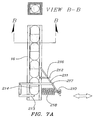
- FIG. 7 A illustrates a first preferred embodiment of the linear transmission system and escapement mechanism
- FIG. 8 illustrates an array of dispensing mechanisms and a frame of actuating members
- FIG. 9 illustrates the system for simultaneously dispensing individual solid products
- FIG. 10 illustrates the system for positioning product package cavities or package templates underneath a plurality of different dispensing mechanisms via a conveyor system
- FIG. 11 illustrates a prefilled magazine for use in conjunction with a present invention
- FIG. 12 A illustrates a recess formed in a panel for defining the two-dimensional cavity having the random orientation of solid pharmaceutical products which receives a batch door mechanism
- FIG. 12 B illustrates the batch door when located within the recess illustrated in FIG. 12 A;
- FIG. 13 illustrates operation of the three-dimensional funnel structure
- FIG. 14 illustrates a mechanism that has been jointly developed with additional inventors which illustrates an embodiment of a system for automatically orienting a three-dimensional random arrangement of solid product into a two-dimensional random orientation
- FIG. 15 illustrates an alternate embodiment for transmitting solid products into a rotating plate.
- FIG. 1 illustrates a first exemplary embodiment of the present invention which is shown generally at 10 .
- an automated alignment mechanism alters the orientation of solid pharmaceutical products that are initially arranged randomly in a two-dimensional array into one or more linear transmission systems.
- a plurality of solid pharmaceutical products 12 are randomly arranged in a two-dimensional array within a cavity that is formed between two generally planar structures.
- the cavity 14 containing the random two-dimensional array of solid pharmaceutical products is located above a plurality of linear transmission systems 16 .
- Each linear transmission system 16 provides a one-dimensional stack of solid pharmaceutical products, vitamins, nutraceuticals or other elements.
- a plurality of wedge-shaped members 18 are shaken by a shaking bar 19 which mechanically displaces the wedge-shaped members 18 up-and-down into the random two-dimensional array of solid pharmaceutical products 12 .
- a variety of different mechanical drives may be provided for generating the vertical displacement of the wedge shaped members 18 .
- pneumatic drives, electrically driven solenoid drives or electric motors may be used for physically moving the wedge shaped members 18 in the cavity 14 .
- FIG. 1 illustrates each of the wedge-shaped members being agitated via a common connecting bar 21 , it is preferred that wedge members that are located at the outermost sides of the cavity are static and the remaining wedge members are alternately static and moving.
- the solid pharmaceutical products 12 are selectively transmitted into individual product package blister cavities or into product package templates having locations corresponding to the blister package cavities via escapement mechanisms 22 .
- escapement mechanisms 22 A variety of different unique escapement mechanisms are also described in more detail below.
- FIG. 2 illustrates in more detail a preferred mechanical drive system for displacing the wedge shaped members 18 and the overall system arrangement.
- the cavity defining panels 32 for containing the solid pharmaceutical products is secured adjacent to the wedge-shaped members 18 .
- the remaining panel for defining the cavity is not shown. During operation, the remaining panel is placed on the other side of the wedge-shaped members 18 so that the cavity is formed between the additional panel and the panel 32 .
- planar members 32 are comprised of a clear plastic material so that an individual operating the packaging machinery can readily visually examine the processing and transmission of a plurality of solid pharmaceutical products.
- planar arrangement of the panels is preferred in order to provide an initial two-dimensional orientation of the product so that the pills or other solid products can be readily oriented in a linear fashion for transmission through the linear transmission channels 16 .
- vertical support members 34 and 35 provide a frame to which the planar members 32 are secured.
- An electric motor 36 is provided for agitating the wedge-shaped members 18 .
- the electric motor 36 is conveniently secured to one of the vertical support members 34 .
- the electric motor 36 rotates a drive shaft 38 that is secure between the vertical support members 34 and 35 .
- the drive shaft 38 also rotates a plurality of cam members 42 which are used to provide the initial downward motion of the wedge-shaped members 18 against springs which are described below. Once the wedge shaped members 18 are released, the springs advantageously quickly displace the wedge-shaped members 18 upward into the random two-dimensional array of solid pharmaceutical products contained between panel members 32 .
- two-dimensional funnels are formed within the cavity defined by the two planar panels 32 .
- the funnels are preferably defined by adjacent wedge shaped members 18 having a thickness which is slightly smaller than the width of the cavity holding the solid pharmaceutical products in a two-dimensional array between the panels 32 .
- an automated shaking mechanism displaces one or more of the wedge shaped members 18 downward and upward in the cavity holding the two-dimensional array of solid pharmaceutical products.
- the wedge-shaped members 18 are mounted on one or more mechanical guides and are in contact with springs that bias the wedge-shaped members into an uppermost position of their range of motion. The precise arrangement of the mechanical guides and the springs which drive the wedge-shaped members are described in more detail below.
- the drive motor 36 rotates the drive shaft 38 having cam members 42 with mechanical contacts 43 that physically displace each of the wedge-shaped members downward against mechanical force of the spring or spring associated with each wedge-shaped member.
- the mechanical contact 43 is essentially a protruding pin member that periodically contacts a mechanical catch 45 when the drive shaft 38 is rotating.
- the catch 45 is secured to any wedge shaped member 18 that is to be agitated.
- the electric motor 36 rotates the drive shaft 38 having the cam members 42 with returning pins 43 that periodically contact the mechanical catch 45 to thereby push each wedge-shaped member 18 downward against the force of one or more springs.
- one or more springs associated with the wedge member quickly forces the wedge member upwardly into the cavity containing the two-dimensional array of solid pharmaceutical products.
- the initial downward and subsequent rapid upward motion of the wedge member rapidly pushes solid pharmaceutical that are located above the wedge member 18 upward and away from the linear transmission channel 16 located at the bottom of the funnel defined by two adjacent wedge members 18 .
- This downward and quick upward physical displacement and the shape of the two-dimensional funnel defined by the adjacent wedge shaped members 18 quickly and conveniently aligns the solid pharmaceutical products so that they readily fall into the linear transmission channels 16 that are located at the bottom of each funnel. Any blockage of the funnel occasioned by the random orientation of the solid pharmaceutical products is quickly eliminated and the linear transmission channels are rapidly filled with the solid pharmaceutical products.
- the two-dimensional cavity defined by the panel members 32 preferably includes a plurality of wedge members 18 generally arranged at a common horizontal position between the panels.
- the arrangement of the adjacent wedge-shaped members 18 defines a plurality of two-dimensional funnels. Each of the two-dimensional funnels is located within the cavity.
- the funnels defined by the adjacent wedge shaped members directly feed into a corresponding linear transmission channel 16 for the solid pharmaceutical products.
- the linear transmission channels provide a one-dimensional arrangement of the solid pharmaceutical products for convenient selective dispensing of the product from the linear transmission channels into a product package cavity.
- a single drive motor 36 and drive shaft 38 located adjacent to the two-dimensional solid pharmaceutical product package cavity includes a plurality of cam members 42 each with a pin 43 and a corresponding mechanical contact 45 that drives a corresponding wedge shaped member 18 .
- one static wedge-shaped member is located adjacent to one of the wedge-shaped members that is physically displaced downward and upward into the cavity having a two-dimensional array of solid pharmaceutical products.
- the wedge-shaped member 48 does not have a mechanical catch 45 secured to its side.
- the wedge-shaped member 48 is therefore static and there is no need to provide a corresponding cam member and mechanical contact for this wedge-shaped member.
- every other wedge-shaped member 18 is a static wedge-shaped member such as the wedge-shaped member 48 . Because it is preferred to have the to outermost funnel portions static, when there is a odd number of channels, it is necessary to have two moving wedges 18 adjacent to each other.
- the wedge-shaped members 18 located between any static wedge-shaped member such as the wedge-shaped member 48 each have a corresponding mechanical catch 45 and associated cam member 42 with corresponding mechanical contact 43 .
- each of the wedge-shaped members 18 for a single two-dimensional array of solid pharmaceutical products is arranged to be slightly out of phase from one another so that the instantaneous load on the drive motor 36 is reduced. More specifically, in the preferred exemplary embodiment, a plurality of static and moving wedge-shaped members are provided across the bottom of the two-dimensional cavity containing the random arrangement of solid pharmaceutical products. In utilizing such approach, every static wedge-shaped member may be separated by intervening wedge shaped members 18 which are physically displaced in the cavity. The desired out of phase displacement of the dynamic wedge-shaped members 18 is readily achieved by having each of the mechanical catch members 45 located at a common horizontal level.
- phase relationship therefore is conveniently achieved by simply locating the mechanical contact members 43 for each of the cam members 42 different locations around the circumference of the drive shaft 38 . Any desired sequential displacement of the dynamic wedge-shaped members 18 is therefore readily achieved by simply adjusting the corresponding location around the drive shaft 38 .
- FIG. 3 illustrates the embodiment of FIG. 2 wherein the electric motor 36 and drive shaft 38 have been eliminated for the purpose of demonstrating the details of the structure behind the drive shaft and the cam members 42 .
- the preferred two-dimensional funnel members that are defined by the panels 32 and the wedge-shaped members 18 feed into linear transmission channels 16 that are provided in correspondence with each funnel.
- the linear transmission channels 16 are preferably arranged vertically beneath a corresponding funnel and may be comprised of a channel that is defined by a plastic or metal tube.
- the tube may be either cylindrical or rectangular and preferably includes wings or spacers which position the individual solid pharmaceuticals in a stack separated from the internal side walls of the tube member.
- the linear transmission channel may be defined by a plurality of metal or plastic rods which define the channel for stacking a plurality of solid pharmaceutical, nutraceutical or other products.
- each of the linear transmission channels may be defined by a metallic spring within which a plurality of the solid pharmaceutical products are stacked.
- FIG. 4 illustrates the details of the agitation mechanism for the embodiment illustrated in FIGS. 2 and 3 .
- each of the linear transmission channels 16 is illustrated as a spring 52 .
- the inventors have discovered that the use of a spring for defining the linear channel 16 is particularly suitable for preventing gel caps from sticking to the sidewalls of the linear transmission channels.
- a metallic spring such as the spring 52 is preferred because springs can be easily mechanically vibrated when the individual solid pharmaceuticals, nutraceuticals or other products are being transferred through the linear transmission channel defined as spring 52 in order to prevent the solid pharmaceutical products from getting stuck within the linear transmission channels.
- the springs 52 have a preferably centrally located spring striker 54 that are each secured to a common spring shaker rod 56 that is preferably movably secured within the frame members 34 and 35 .
- At least one spring shaker drive member 58 is moved up and down as a result of the rotation of the drive shaft 38 .
- the spring shaker drive member 58 includes a protruding portion 59 that is used to laterally displace the spring shaker rod 56 .
- each spring shaker drive member 58 is secured to one of the dynamic wedge-shaped members 18 . Accordingly, the spring shaker drive 58 moves up-and-down with its corresponding dynamic wedge-shaped member 18 when the corresponding pin 43 of the associated cam 42 strikes the catch 45 .
- each spring striker 54 preferably has an inner diameter that is greater than the spring 52 located within the spring striker 54 .
- at least one additional spring striker return spring 62 is provided on an opposite side of each spring striker 54 .
- the additional spring striker return springs 62 simply pull each spring striker back in a direction opposite from the direction of motion caused by the protruding member 59 so that when the spring striker 54 is moved away from its initial position, it quickly returns toward the spring 52 .
- the protrusion 59 is designed to be of a shape such that immediately after reaching a greatest distance from the spring striker return spring 62 , the spring striker 54 moves quickly back toward the spring 52 , so that it strikes the spring and causes a high-frequency vibration of the spring 52 .
- the high high-frequency vibration of the spring 52 desirably eliminates any blockage of the linear transmission channel 16 defined by the spring 52 .
- FIG. 4 Another aspect of the design illustrated in FIG. 4 is a notched portion 64 of the wedge member 18 .
- the notched portion 64 of the wedge member 18 is positioned and formed such that when a wedge 18 is at its lowermost position, the outermost portions of two adjacent wedges defines a beginning of the linear transmission channel.
- the notched portion 64 is adjacent an uppermost side of the spring 52 and the outermost portion of each wedge member above the notch extends to be at or around the inside diameter of the spring 52 .
- a wedge spacer 65 is provided and secured to the panel 32 . The wedge spacer 65 ensures that the appropriate transmission channel dimensions extend adjacent to the wedge members 18 regardless of the vertical position of the wedge.
- FIG. 5 illustrates in greater detail the aspects of the overall system directed to vibrating the linear transmission channels defined by springs 52 and displacing wedge shaped members 18 .
- the movable wedge-shaped members 18 are movably secured via left and right pin guides 66 , 67 .
- Each of the dynamic wedge-shaped members 18 is preferably mounted upon at least two of these guides.
- the left and right pin guides 66 , 67 are located within wedge-driving springs 68 , 69 that rest upon base 70 .
- the wedge driving springs 68 , 69 are used to bias the wedge-shaped members 18 in an uppermost position of their range of motion.
- the mechanical catch 45 is driven by a mechanical contact that is not shown in this illustration.
- the wedge-shaped members 18 are driven downward against the force of the wedge-driving springs 68 , 69 .
- the wedge driving springs 68 , 69 immediately force the wedge-shaped member upward thereby dislodging any blockage of the funnel or linear transmission channel.
- FIG. 5 illustrates yet another alternate aspect of the present invention which is directed to the use of a channel insert 72 that conveniently alters the interior of the linear transmission channel defined by the spring 52 . More specifically, this flat metal or plastic channel insert 72 is used only when the medication or solid product is not round in cross-section and/or there is no circular symmetry for the product. Advantageously, the use of the channel insert 72 alters the interior dimensions of the channel so that pills which are not circular in cross-section can more easily transit through the channel without blocking the linear transmission channel.
- FIG. 5 also illustrates the wedge spacer 65 attachment points 73 that are provided for securing the wedge spacer 65 to the panel 32 .
- FIG. 6A illustrates a first alternate exemplary embodiment of the escapement mechanism which is shown generally at 100 .
- a vertical drive member 110 selectively toggles upper 112 and lower 113 solid pharmaceutical product catcher mechanisms which ensure that only one solid pharmaceutical product is delivered as desired from the linear transmission channel 16 .
- the lowermost catcher mechanism 113 prevents the lowest solid pharmaceutical product 114 from escaping the linear transmission channel 16 .
- the toggling action of this device is achieved as a result of the convenient vertical displacement of the vertical drive member 110 .
- the vertical drive member 110 is shaped to alternately mechanically displace the upper 112 and lower 113 solid pharmaceutical product catch mechanisms based on the up-and-down motion of the vertical drive member 110 .
- the upper 112 and lower 113 solid pharmaceutical product catcher mechanisms each respectfully include corresponding drive contacts 116 , 117 that mechanically interact with the vertical drive member 110 having outwardly angled upper and lower portions which enable the vertical displacement of the vertical drive member 110 and the sliding action across the upper and lower drive contacts 116 , 117 to conveniently enable the toggling of the upper and lower product catch mechanisms 112 , 113 .
- the central portion of the vertical drive member 110 is in contact with the upper drive contact 116 and the outwardly angled lower portion of the vertical drive member 110 is in contact with the lower drive contact 117 .
- the lower solid pharmaceutical catcher mechanism is moved away from the solid products and allows them to pass while the upper solid pharmaceutical catcher mechanism 113 blocks any additional products from passing.
- Upper 118 and lower 119 catcher displacement spring ensures that the upper 112 and lower 113 solid pharmaceutical product catcher mechanisms are biased against the vertical drive member 110 .
- the vertical drive member 110 thereafter moves downward and this downward motion of the vertical drive member positions the lower catch mechanism 113 back into the channel 16 and the upper catch 112 is moved away from the channel 16 .
- This alternate arrangement thereby enables all solid pharmaceutical products within the channel to drop by one position such that the remaining lowermost solid pharmaceutical product moves into contact with the lowermost catch mechanism 113 .
- FIG. 6B is a cross-sectional view of the linear transmission channel 16 . As shown in FIG. 6B , spacer wings are formed within the channel to move the solid pharmaceutical product 12 away from the sidewalls of the linear transmission channel.
- FIG. 7 illustrates a first alternate exemplary embodiment of the escapement mechanism which is shown generally at 200 .
- a horizontal support member 210 provides support for the operation of the structures described hereafter.
- the toggling of upper 212 and lower 213 solid pharmaceutical product catcher mechanisms ensure that only one solid pharmaceutical product is delivered as desired from the linear transmission channel 16 .
- the lowermost catcher mechanism 213 prevents the lowest solid pharmaceutical product 214 from escaping the linear transmission channel 16 .
- the toggling action of this device is achieved as a result of the convenient horizontal movement against the lever 211 .
- the lever 211 alternately mechanically displaces the upper 212 and lower 213 solid pharmaceutical product catch mechanisms based on the lateral motion of the lever 211 .
- the upper 212 and lower 213 solid pharmaceutical product catcher mechanisms each respectfully include corresponding drive contacts 216 , 217 that mechanically interact with the lever member 211 to conveniently enable the toggling of the upper and lower product catch mechanisms 212 , 213 based on the convenient horizontal displacement of the lever 211 .
- the lever 211 When the lever 211 is at its leftmost position, the lever member 211 pushes the upper solid pharmaceutical product catcher mechanism 212 into the linear transmission channel 16 also pushing of the lower catcher mechanism 213 away from the channel. In this orientation, the lower solid pharmaceutical catcher mechanism 213 is moved away from the solid products and allows them to pass while the upper solid pharmaceutical catcher mechanism 212 blocks any additional products from passing.
- a single horizontal drive displacement spring 218 pushes outward against the lever 211 .
- the simple sliding action of the horizontal drive member is able to toggle the upper 212 and lower 213 solid pharmaceutical product catcher mechanisms.
- the lever 211 moves outward and this outward motion of the lever 211 positions the lower catch mechanism 213 back into the channel 16 and the upper catch 212 is moved away from the channel 16 .
- This alternate arrangement thereby enables all solid pharmaceutical products within the channel to drop by one position such that the remaining lowermost solid pharmaceutical product moves into contact with the lowermost catch mechanism 213 .
- the toggling action of the device thereby enables the selective dropping of the solid pharmaceutical product or vitamin from the linear transmission channel 16 into a solid pharmaceutical product package cavity or temporary storage mechanism that is located beneath the linear transmission channel.
- Triggering of the toggling action for the escapement mechanism may be achieved in a variety of different manners such as, for example, via the use of an electronic solenoid, an electric motor drive, or a pneumatic drive.
- an electronic solenoid such as, for example, via the use of an electric motor drive, or a pneumatic drive.
- Those skilled in the art will appreciate that the specific mechanical actuator is not critical to the operation of the device.
- FIG. 8A illustrates a preferred exemplary embodiment of the present invention wherein the funnels and linear transmission channels having corresponding escapement mechanisms are preferably provided in two-dimensional array that is shown generally at 300 . It is particularly preferred that the exit locations for the solid pharmaceutical products correspond with desired locations of a corresponding blister package cavity or temporary storage mechanism associated with locations corresponding to a blister package cavity. The inventors have discovered that dramatic increases in packaging efficiency and speed can be achieved by utilizing one or more arrays of the described dispensing mechanisms for filling solid pharmaceutical product packaging.
- a one-dimensional linear array having funnels and linear transmission channels corresponding to each member of a complete row of blister package cavities in a solid pharmaceutical product package can be utilized to simultaneously fill each cavity or the location of a product package template corresponding to each cavity in the row. More specifically, in such embodiment, the escapement mechanism for each linear transmission channel can be triggered at the same time to simultaneously fill each row.
- FIG. 8 A illustrates a top plan view of a plurality of linear transmission channels that are positioned within a frame of actuating members.
- the actuating members may push against the actuating members for the escapement mechanisms provided above.
- This frame advantageously enables a large number of linear transmission channels to be activated simultaneously.
- the frame members can be designed to include each of an upper and lower catch mechanism for a plurality of linear transmission channels arranged in an array. In such an alternate embodiment, movement of the frame itself automatically toggles the catch and release of pharmaceutical products in the linear transmission channels that are located within the array.
- FIG. 8 B illustrates a plurality of upper catchers 303 and lower shutters 305 for simultaneously releasing an individual solid product from a plurality of linear transmission channels.
- FIG. 9A illustrates yet another alternate embodiment wherein a matrix of funnels and linear transmission channels corresponding to a plurality of rows of blister package cavities or corresponding to all rows of cavities in a blister package or product package template is provided.
- the same medications may be provided in the array in order to simultaneously fill all cavities with the same medications.
- different medications may be provided in each row of the array in order to selectively locate different medications from positions in the array into desired product package cavities or the locations of a package template corresponding to the blister package cavities.
- a plurality of rows of linear transmission channels 315 are located directly above the plurality of blister package cavities for pharmaceutical product package.
- FIG. 9 B illustrates a plurality of rows of linear transmission channels 315 located adjacent to a blister package sheet 317 .
- FIG. 10 illustrates yet another alternate aspect of the present invention wherein a conveyor 350 is provided for the purpose of moving blister package cavities or package templates beneath one or more arrays of the above-described dispensing mechanisms in order to provide greater flexibility in the different types of medications that may be inserted into the blister package cavities for patient use.
- a conveyor 350 is provided for the purpose of moving blister package cavities or package templates beneath one or more arrays of the above-described dispensing mechanisms in order to provide greater flexibility in the different types of medications that may be inserted into the blister package cavities for patient use.
- the only limitation placed upon the number of different medications that can be inserted into the blister package cavities is the number of different types of medications contained in rows of the dispensing mechanisms.
- the conveyor positions the blister package cavities or a package template corresponding to the locations of the blister package cavities beneath each desired row.
- Such an arrangement would provide a system that is capable of filling virtually any type of medication that is typically desired or used in a normal hospital or managed care facility.
- FIG. 11 illustrates yet another alternate aspect of the present invention that is directed to the use of a pre-filled magazine 301 containing a two-dimensional random array of the solid pharmaceutical products.
- the pre-filled magazine 301 may be conveniently placed directly over the cavity within which the wedge shaped members are positioned.
- a sliding door 310 is located at the bottom of the pre-filled magazine 301 .
- the sliding door 310 is preferably manually opened in order to allow the medications to freely move into position above the wedge shaped members so that the solid pharmaceutical products may rearranged from a two-dimensional random array into a one-dimensional linear stack for placement into individual package cavities as described above.
- the pre-filled magazines may be manually filled or an automated system may be provided for filling the magazines.
- a hinge is provided to conveniently open the internal cavity of the magazine 301 for manual filling of the magazine.
- one of the panel members be secured via pin members for convenient access to the cavity.
- FIG. 12 A illustrates an exemplary embodiment of a batch door cavity 375 formed within a panel 35 for use in conjunction with the present invention which is generally shown at 330 .
- the inventors of the instant application have discovered that the random two-dimensional arrangement of pharmaceutical products is more readily achieved if there is some free-space provided above the wedge-shaped members 18 .
- the space provided above the wedge-shaped members 18 enables the upward displacement of the wedge-shaped members to more easily move upward away from the wedge members. This motion allows for re-orientation of the solid products so that the funnels can direct the products into the linear transmission channels.
- the batch doors also limit the downward force that is caused by the cumulative effect of the solid products.
- the inventors have discovered that when a large number of the solid pharmaceutical products are provided above the wedge-shaped members, the greater downward force on the lowest product members increases the potential for jamming of the funnels.
- the batch doors limit the downward force on the lowest individual products.
- a batch door is comprised of a protruding member that is located in a linear cavity 375 that is formed in the side of one of the planar side walls 35 which forms the two-dimensional cavity space.
- the protruding member or batch door 380 simply moves into or away from the cavity space in order to prevent additional solid pharmaceutical products from moving toward the wedge-shaped members.
- the batch door 380 may be comprised of a pneumatically driven expandable bladder which when activated pushes against the solid products located adjacent to the batch door 380 in the cavity.
- the bladder is preferably comprised of a rubber material 381 that is located over a metal tube 382 with a slit therein that is located within the slot 375 .
- the batch door 380 may simply move into the cavity to block any additional solid products from passing toward the wedge-shaped members.
- a metal or plastic rod located within the cavity 375 can be pushed out to catch any solid pharmaceutical products.
- a three-dimensional funnel is provided such that two or more distinct portions define the funnel structure and at least one portion of the funnel structure is vertically displaced for the purpose of altering the three-dimensional random orientation of solid pharmaceutical products within the funnel.
- This approach uses the same general concept as the motion of the wedge-shaped members within the two-dimensional cavity for orienting the solid pharmaceutical products but it does not require an initial step of arranging the solid pharmaceutical products in a two-dimensional cavity.
- FIG. 13 illustrates an embodiment wherein the wedge-shaped members 18 are portions of three dimensional bodies defining the funnel members 18 .
- the moving portion of the funnel could be one third or one half of the overall structure.
- FIG. 13 also illustrates baffles 384 that prevent the solid pharmaceutical products from moving within the three-dimensional cavity.
- FIG. 14 illustrates a mechanism for automatically translating solid pharmaceutical or nutraceutical products from a random three-dimensional orientation into a random two-dimensional array.
- Sidewalls 410 define an upper three-dimensional cavity within which solid pharmaceutical or nutraceutical products are located.
- Buffer members 411 prevent the solid pharmaceutical products from the exerting too much downward force in the lowermost portion of the device. This arrangement aids in preventing jamming.
- Elongated panels 420 on opposite sides directed the solid pharmaceuticals toward a two-dimensional cavity 425 .
- a roller 423 turns counterclockwise and kicks up any improperly oriented product members.
- a vertical drive plate 422 moves upward and downward adjacent to the topmost portion of the two-dimensional cavity 425 .
- the combination of the counterclockwise roller 423 and the vertical drive plate 422 has been found to be an efficient mechanism for altering a variety of different solid pharmaceutical products from a random three-dimensional arrangement into a two-dimensional array.
- the roller can be replaced by another vertical drive plate.
- FIG. 15 shows yet another alternate embodiment wherein cone shape rollers 480 , 481 direct solid pharmaceutical products into cavities that are located within the circular rotating plate 485 .
- the rotating plate 485 preferably includes a mechanism for selectively transmitting the solid products away from the rotating plate.
- the escapement mechanisms described above are suitable for this purpose.
- the half-moon shaped structures are protrusions secured to the rotating plate which are intended to contact the triggering mechanism actuator described above so that the escapement mechanism is triggered at the desired point of rotation.
- each wedge-shaped member is approximately 30° to 45° measured from the perpendicular along a side of the wedge member. It is presently preferred that the wedge shaped members are displaced approximately one half of an inch for a long capsule and 0.4 of an inch for a smaller tablet. The spacing between the panels is a few percent larger than the diameter of the pills in the desired orientation. Each spring preferably has three to five coils of pitch per tablet length in the desired orientation.
Abstract
Description
Claims (10)
Priority Applications (1)
| Application Number | Priority Date | Filing Date | Title |
|---|---|---|---|
| US11/509,244 US8096100B2 (en) | 2005-08-24 | 2006-08-23 | Systems and methods for packaging solid pharmaceutical and/or nutraceutical products and automatically arranging the solid pharmaceutical and nutraceutical products in a linear transmission system |
Applications Claiming Priority (2)
| Application Number | Priority Date | Filing Date | Title |
|---|---|---|---|
| US71078405P | 2005-08-24 | 2005-08-24 | |
| US11/509,244 US8096100B2 (en) | 2005-08-24 | 2006-08-23 | Systems and methods for packaging solid pharmaceutical and/or nutraceutical products and automatically arranging the solid pharmaceutical and nutraceutical products in a linear transmission system |
Publications (2)
| Publication Number | Publication Date |
|---|---|
| US20070044432A1 US20070044432A1 (en) | 2007-03-01 |
| US8096100B2 true US8096100B2 (en) | 2012-01-17 |
Family
ID=37772413
Family Applications (1)
| Application Number | Title | Priority Date | Filing Date |
|---|---|---|---|
| US11/509,244 Active US8096100B2 (en) | 2005-08-24 | 2006-08-23 | Systems and methods for packaging solid pharmaceutical and/or nutraceutical products and automatically arranging the solid pharmaceutical and nutraceutical products in a linear transmission system |
Country Status (2)
| Country | Link |
|---|---|
| US (1) | US8096100B2 (en) |
| WO (2) | WO2007025078A2 (en) |
Cited By (4)
| Publication number | Priority date | Publication date | Assignee | Title |
|---|---|---|---|---|
| US20100154354A1 (en) * | 2008-12-22 | 2010-06-24 | Uhlmann Pac-Systeme Gmbh & Co. Kg | Device for filling packaging receptacles with pharmaceutical products |
| US11235895B2 (en) * | 2012-06-01 | 2022-02-01 | Rxsafe Llc | Pharmacy packaging system |
| US11724837B2 (en) | 2012-06-01 | 2023-08-15 | Rxsafe Llc | Pharmacy packaging system |
| US11753193B2 (en) | 2019-05-03 | 2023-09-12 | Rxsafe Llc | Pharmacy packaging system and pouch |
Families Citing this family (1)
| Publication number | Priority date | Publication date | Assignee | Title |
|---|---|---|---|---|
| CN105599988A (en) * | 2015-10-21 | 2016-05-25 | 华侨大学 | Method for parallelly sub-packaging sequential materials |
Citations (19)
| Publication number | Priority date | Publication date | Assignee | Title |
|---|---|---|---|---|
| US2577394A (en) | 1946-06-11 | 1951-12-04 | Zunino Carl | Dispensing machine |
| US2809768A (en) * | 1953-08-06 | 1957-10-15 | Koerber & Co Kg | Apparatus for withdrawing rod-like articles from a supply container |
| US3129544A (en) | 1960-06-28 | 1964-04-21 | Delta Engineering Corp | Apparatus for conveying and filling containers |
| US3537230A (en) | 1968-04-09 | 1970-11-03 | Federal Carton Corp | Box loading machine |
| US3730388A (en) | 1972-02-10 | 1973-05-01 | Brenner & Bender Inc | Material measuring and dispensing apparatus |
| US3774368A (en) | 1972-06-19 | 1973-11-27 | H Paprzycki | Tablet counting and filling apparatus |
| US4460108A (en) * | 1979-05-12 | 1984-07-17 | Sony Corporation | Apparatus for feeding electric circuit elements |
| US4480982A (en) * | 1983-02-07 | 1984-11-06 | Brown & Williamson Tobacco Corporation | Apparatus for making grooves in cigarette filters |
| US4614263A (en) * | 1983-09-13 | 1986-09-30 | Japan Tobacco, Inc. | Cigarette arranging apparatus |
| US5101612A (en) | 1990-04-26 | 1992-04-07 | Nippon Elanco Kabushiki Kaisha | Capsule filling apparatus |
| US5525023A (en) * | 1992-12-10 | 1996-06-11 | Matsushita Electric Industrial Co., Ltd. | Chip component supply apparatus |
| US5829632A (en) | 1997-02-11 | 1998-11-03 | Gemel Precision Tool Co., Inc. | Flexible band pharmaceutical product feeder gate assembly |
| US5992611A (en) | 1998-04-21 | 1999-11-30 | Motorola, Inc. | Concurrent component mounter and method of concurrently mounting components |
| US6073800A (en) | 1996-11-15 | 2000-06-13 | Taiyo Yuden Co., Ltd. | Chip component feeding apparatus and attracting plate for use in same |
| US6298976B1 (en) | 1999-01-23 | 2001-10-09 | Topack Verpackungstechnik Gmbh | Device for assembling article groups from rod-shaped articles in the tobacco-processing industry |
| US6336573B1 (en) * | 1998-04-06 | 2002-01-08 | Andritz-Ahlstrom Inc. | Hopper, or bin, screw feeder construction controlling discharge velocity profile |
| US6405895B1 (en) * | 1999-05-12 | 2002-06-18 | Fuji Machine Mfg. Co., Ltd. | Arranging and supplying apparatus |
| US6443669B2 (en) * | 1999-12-24 | 2002-09-03 | Taiyo Yuden Co., Ltd. | Electronic component feeding apparatus |
| US6497083B1 (en) | 1999-11-10 | 2002-12-24 | Electro-Mec (Reading) Ltd | Packaging apparatus |
-
2006
- 2006-08-23 WO PCT/US2006/033136 patent/WO2007025078A2/en active Application Filing
- 2006-08-23 US US11/509,244 patent/US8096100B2/en active Active
- 2006-08-24 WO PCT/US2006/033265 patent/WO2007025156A2/en active Application Filing
Patent Citations (20)
| Publication number | Priority date | Publication date | Assignee | Title |
|---|---|---|---|---|
| US2577394A (en) | 1946-06-11 | 1951-12-04 | Zunino Carl | Dispensing machine |
| US2809768A (en) * | 1953-08-06 | 1957-10-15 | Koerber & Co Kg | Apparatus for withdrawing rod-like articles from a supply container |
| US3129544A (en) | 1960-06-28 | 1964-04-21 | Delta Engineering Corp | Apparatus for conveying and filling containers |
| US3537230A (en) | 1968-04-09 | 1970-11-03 | Federal Carton Corp | Box loading machine |
| US3730388A (en) | 1972-02-10 | 1973-05-01 | Brenner & Bender Inc | Material measuring and dispensing apparatus |
| US3774368A (en) | 1972-06-19 | 1973-11-27 | H Paprzycki | Tablet counting and filling apparatus |
| US4460108A (en) * | 1979-05-12 | 1984-07-17 | Sony Corporation | Apparatus for feeding electric circuit elements |
| US4480982A (en) * | 1983-02-07 | 1984-11-06 | Brown & Williamson Tobacco Corporation | Apparatus for making grooves in cigarette filters |
| US4614263A (en) * | 1983-09-13 | 1986-09-30 | Japan Tobacco, Inc. | Cigarette arranging apparatus |
| US5101612A (en) | 1990-04-26 | 1992-04-07 | Nippon Elanco Kabushiki Kaisha | Capsule filling apparatus |
| US5525023A (en) * | 1992-12-10 | 1996-06-11 | Matsushita Electric Industrial Co., Ltd. | Chip component supply apparatus |
| US6073800A (en) | 1996-11-15 | 2000-06-13 | Taiyo Yuden Co., Ltd. | Chip component feeding apparatus and attracting plate for use in same |
| US6308861B1 (en) * | 1996-11-15 | 2001-10-30 | Taiyo Yuden Co., Ltd. | Chip component feeding apparatus and attracting plate for use in same |
| US5829632A (en) | 1997-02-11 | 1998-11-03 | Gemel Precision Tool Co., Inc. | Flexible band pharmaceutical product feeder gate assembly |
| US6336573B1 (en) * | 1998-04-06 | 2002-01-08 | Andritz-Ahlstrom Inc. | Hopper, or bin, screw feeder construction controlling discharge velocity profile |
| US5992611A (en) | 1998-04-21 | 1999-11-30 | Motorola, Inc. | Concurrent component mounter and method of concurrently mounting components |
| US6298976B1 (en) | 1999-01-23 | 2001-10-09 | Topack Verpackungstechnik Gmbh | Device for assembling article groups from rod-shaped articles in the tobacco-processing industry |
| US6405895B1 (en) * | 1999-05-12 | 2002-06-18 | Fuji Machine Mfg. Co., Ltd. | Arranging and supplying apparatus |
| US6497083B1 (en) | 1999-11-10 | 2002-12-24 | Electro-Mec (Reading) Ltd | Packaging apparatus |
| US6443669B2 (en) * | 1999-12-24 | 2002-09-03 | Taiyo Yuden Co., Ltd. | Electronic component feeding apparatus |
Cited By (6)
| Publication number | Priority date | Publication date | Assignee | Title |
|---|---|---|---|---|
| US20100154354A1 (en) * | 2008-12-22 | 2010-06-24 | Uhlmann Pac-Systeme Gmbh & Co. Kg | Device for filling packaging receptacles with pharmaceutical products |
| US8826631B2 (en) * | 2008-12-22 | 2014-09-09 | Uhlmann Pac-Systeme Gmbh & Co. Kg | Device for filling packaging receptacles with pharmaceutical products |
| US11235895B2 (en) * | 2012-06-01 | 2022-02-01 | Rxsafe Llc | Pharmacy packaging system |
| US11724837B2 (en) | 2012-06-01 | 2023-08-15 | Rxsafe Llc | Pharmacy packaging system |
| US11760512B2 (en) | 2012-06-01 | 2023-09-19 | Rxsafe Llc | Pharmacy packaging system |
| US11753193B2 (en) | 2019-05-03 | 2023-09-12 | Rxsafe Llc | Pharmacy packaging system and pouch |
Also Published As
| Publication number | Publication date |
|---|---|
| WO2007025078A3 (en) | 2007-05-31 |
| WO2007025156A3 (en) | 2007-06-14 |
| WO2007025078A2 (en) | 2007-03-01 |
| WO2007025078B1 (en) | 2007-07-19 |
| WO2007025156A2 (en) | 2007-03-01 |
| US20070044432A1 (en) | 2007-03-01 |
Similar Documents
| Publication | Publication Date | Title |
|---|---|---|
| US7523594B2 (en) | Systems and methods for packaging solid pharmaceutical and/or nutraceutical products and automatically arranging the solid pharmaceutical and nutraceutical products in a linear transmission system | |
| US8096100B2 (en) | Systems and methods for packaging solid pharmaceutical and/or nutraceutical products and automatically arranging the solid pharmaceutical and nutraceutical products in a linear transmission system | |
| EP1294610B1 (en) | Medication dispenser | |
| EP0502526B1 (en) | Drug dispenser | |
| JP4947271B2 (en) | Method for filling tablets into capsule body and device for filling tablets into capsules using the filling method | |
| EP2134610B1 (en) | Systems and methods for removing medication from packaging | |
| US20130105277A1 (en) | Drug Sorting Device | |
| AU2013284337A1 (en) | Solid dose feeder and operating method thereof | |
| US4955783A (en) | Device for forming a pile of blister packs in an upward direction | |
| US20070278240A1 (en) | Apparatus for Dispensing of Stacked Objects, a Method for Dispensing Stacked Objects and a System Comprising an Apparatus for Dispensing | |
| US7861846B1 (en) | Singulating apparatus | |
| US9624047B2 (en) | Container denester apparatus | |
| US8714406B2 (en) | Container denester apparatus | |
| EP2544950B1 (en) | Blister sheet loading apparatus with bounce prevention means | |
| US7267036B1 (en) | Vial card slitting apparatus | |
| JP6118977B2 (en) | Dispensing device medicine dispensing mechanism | |
| AU2001261921B2 (en) | Medication dispenser | |
| KR101708771B1 (en) | Pills conveyance device capable of corresponding to various size pills | |
| AU2001261921A1 (en) | Medication dispenser |
Legal Events
| Date | Code | Title | Description |
|---|---|---|---|
| AS | Assignment |
Owner name: GREENWALD TECHNOLOGIES, LLC, NEW YORK Free format text: ASSIGNMENT OF ASSIGNORS INTEREST;ASSIGNORS:GREENWALD, SHLOMO;GREENWALD, ZIPORA;REEL/FRAME:022515/0015 Effective date: 20090403 |
|
| AS | Assignment |
Owner name: GCI CAPITAL MARKETS LLC, AS ADMINISTRATIVE AGENT, Free format text: SECURITY AGREEMENT;ASSIGNOR:MTS MEDICATION TECHNOLOGIES, INC.;REEL/FRAME:026464/0285 Effective date: 20110615 |
|
| AS | Assignment |
Owner name: MTS MEDICATION TECHNOLOGIES, INC., FLORIDA Free format text: RELEASE BY SECURED PARTY;ASSIGNOR:GCI CAPITAL MARKETS LLC;REEL/FRAME:027358/0959 Effective date: 20111208 |
|
| STCF | Information on status: patent grant |
Free format text: PATENTED CASE |
|
| AS | Assignment |
Owner name: MTS MEDICATIONS TECHNOLOGIES, INC., DISTRICT OF CO Free format text: RELEASE BY SECURED PARTY;ASSIGNOR:GCI CAPITAL MARKETS LLC;REEL/FRAME:028272/0563 Effective date: 20120521 |
|
| AS | Assignment |
Owner name: WELLS FARGO BANK, NATIONAL ASSOCIATION, AS ADMINIS Free format text: SECURITY AGREEMENT;ASSIGNOR:MTS MEDICATION TECHNOLOGIES, INC.;REEL/FRAME:031301/0958 Effective date: 20130925 |
|
| FPAY | Fee payment |
Year of fee payment: 4 |
|
| AS | Assignment |
Owner name: MTS MEDICATION TECHNOLOGIES, INC., FLORIDA Free format text: RELEASE BY SECURED PARTY;ASSIGNOR:WELLS FARGO BANK, NATIONAL ASSOCIATION, AS ADMINISTRATIVE AGENT;REEL/FRAME:037424/0971 Effective date: 20160105 |
|
| FEPP | Fee payment procedure |
Free format text: PAT HOLDER NO LONGER CLAIMS SMALL ENTITY STATUS, ENTITY STATUS SET TO UNDISCOUNTED (ORIGINAL EVENT CODE: STOL); ENTITY STATUS OF PATENT OWNER: LARGE ENTITY |
|
| MAFP | Maintenance fee payment |
Free format text: PAYMENT OF MAINTENANCE FEE, 8TH YEAR, LARGE ENTITY (ORIGINAL EVENT CODE: M1552); ENTITY STATUS OF PATENT OWNER: LARGE ENTITY Year of fee payment: 8 |
|
| MAFP | Maintenance fee payment |
Free format text: PAYMENT OF MAINTENANCE FEE, 12TH YEAR, LARGE ENTITY (ORIGINAL EVENT CODE: M1553); ENTITY STATUS OF PATENT OWNER: LARGE ENTITY Year of fee payment: 12 |