US80942A - gould - Google Patents
gould Download PDFInfo
- Publication number
- US80942A US80942A US80942DA US80942A US 80942 A US80942 A US 80942A US 80942D A US80942D A US 80942DA US 80942 A US80942 A US 80942A
- Authority
- US
- United States
- Prior art keywords
- same
- saws
- gauges
- abutment
- board
- Prior art date
- Legal status (The legal status is an assumption and is not a legal conclusion. Google has not performed a legal analysis and makes no representation as to the accuracy of the status listed.)
- Expired - Lifetime
Links
- 239000002023 wood Substances 0.000 description 6
- 210000001503 Joints Anatomy 0.000 description 4
- 238000010586 diagram Methods 0.000 description 4
- 206010022114 Injury Diseases 0.000 description 2
- 230000023298 conjugation with cellular fusion Effects 0.000 description 2
- 230000000875 corresponding Effects 0.000 description 2
- 230000000694 effects Effects 0.000 description 2
- XEEYBQQBJWHFJM-UHFFFAOYSA-N iron Substances [Fe] XEEYBQQBJWHFJM-UHFFFAOYSA-N 0.000 description 2
- 229910052742 iron Inorganic materials 0.000 description 2
- 210000001699 lower leg Anatomy 0.000 description 2
- 230000013011 mating Effects 0.000 description 2
- 239000002184 metal Substances 0.000 description 2
- 229910052751 metal Inorganic materials 0.000 description 2
- 239000007779 soft material Substances 0.000 description 2
- 230000021037 unidirectional conjugation Effects 0.000 description 2
Images

Classifications
-
- B—PERFORMING OPERATIONS; TRANSPORTING
- B27—WORKING OR PRESERVING WOOD OR SIMILAR MATERIAL; NAILING OR STAPLING MACHINES IN GENERAL
- B27F—DOVETAILED WORK; TENONS; SLOTTING MACHINES FOR WOOD OR SIMILAR MATERIAL; NAILING OR STAPLING MACHINES
- B27F1/00—Dovetailed work; Tenons; Making tongues or grooves; Groove- and- tongue jointed work; Finger- joints
- B27F1/02—Making tongues or grooves, of indefinite length
- B27F1/04—Making tongues or grooves, of indefinite length along only one edge of a board
Definitions
- Figure 2 is a plan or top view ofthe same.
- Figure 3 is a detached sectional view of one of the gauges.
- Figures 4, 5, 6, and? are diagrams illustrating the manner in which the saws cut.
- This invention relates to certain improvements v-in that classof dove-tailing machines in which t'wo sets of s saws are employed, one set for producing the tenons,landthe other the mortises or grooves.
- the invention consists in cutting dove-tails from thel bottoms ofl the grooves, or of the spaces between the tencns, in such a manner that the distance between said bottoms becomes independent of the edges of theY boards, and said distance will be'true and correct, even if the opposite edges of a board should not be parallel; also, in the arrangement'of adjustable stops, secured to the upright gauges, and made in suchta shape that they can be brought to bear on the bottoms of ⁇ the grooves or spaces between the tenonsfand the operation of cutting the dove-tails-from the bottoms of the grooves or spaces is materially facilitated; further, in *thev arrangement of a' movable fulcrum, in combination with the swinging abutment, in such a manner that by adjusting the fulcruin, a certain motio'n transversely tothe carriage is imparted to ⁇ said abutment according t ⁇ o the desired width of the grooves or the spaces between the tenons; also
- arr adjustable slide in combination witha gang ofsaws in such a manner that Athe position of the board in'relaton to the saws can be readily adjusted; also, in the arrangement of two ⁇ upright gauges, provided with slides, in one and the same abutment, in such a manner Vthat the cutting of dove-tails from one and 'the same face or side ofthe boardis facilitated; further, in the arrangement of two stationary abutments extending across the carriage in diierent directions, and at angles which are supplements toY each other, said abutments being provided with upright gauges and slides in such a mannerthat by placing the boards 4successively against the abutments, the operation of cutting the dove-tails can be e'ected from one and the same side -orvface of' the boards.
- t A represents a frame, which forms the bearings for two'shafts, B C, and whichis provided with two distinct guido-ways, a a, 6 b, as clearly shown Vin the drawing.
- a Y y On the shaft B is mounted a serios of saws, D, which serve to cut the grooves or mortises, and on the guide-ways a a is fitted thecarriage E, from which rise the gauges F F. l
- the cutting-edges or faces of the saws1 are oblique, or at an angle toward the longitudinal centre of their axio, and the gauges are so placed that their inner or working faces are' exactly at right angles'toy a line connecting the cutting-edges of the various saws.
- Each of the gauges l is provided with a slide, c, which can be move'd up or down in a slot, and which is securcd'in the desired position by a set-screw, d.
- Each slide is provided with a slot, to receive al stop, e e', which is secured in the desired position'by a nut, f, screwingon the shank of the stop.
- the strop can be adjusted up anddown by moving the slide in itslslot, and it can alsoibe set closer to Vor farther from the working face of, its gauge, to suit the work tobe produced.
- the gauges F F are adjustable in their carriage E, according to the width of the board into which the grooves are to be cut, and the distance desired from the edge of the board tothe nearest groovc, and according to the desired width ofthe grooves.
- the slides c are set, so that the stops e and e are placed at the same distance from the top of the saws, and to correspond to the height or length of the board desired fromthe inside ofthe first row of grooves to be eut..
- the board is placed withl one edge against the gauge F, with its upper end bearing against thestop e, and pushing the carriage forward, theboard is carried across thesaws, and a centsof cuts is produced, such as shown in fig. 4.
- the board is then reversed, so thatthe same edge is against the gauge F that was against gauges F before, leaving the same'cnd up to bearagainst the stop e', and the board is carried againl'over the-saws, whereby the grooves on one end ofthe board are finished in the form shown in Eg.'5, where the letter o represents the first or old and letter 'a the second or new cut.
- the board is turned upside down, and the stops e e are so adjusted that they will bear against the bottoms or inside of the grooves, as shown in fig. 1.
- the grooves at the opposite edge'ot ⁇ the board are then finished in the same manner as above described.
- the gaugespor stops are always brought to bear on the end of the hoard to be cut, and if the two ends are not perfectly parallel, or the boards not of the same length, the distances between the bottoms .ofthe grooves of the two ends become unequal, and the lboxes or other work produced will not be square, whereas, if the distance between the bottoms of the grooves is made exact, as in my machine, the work necessarily becomes square, and the surplus ⁇ wood projecting beyond the edges can be readily planed off after the several boardshave 'been fitted together, as is done in making dove-tailed joints by hand, leaving the joints smooth and perfect, which would not be the case if the boards were n
- the abutment I which is provided with a slot, so that said gauge canbe adjusted to suit the width of the boards and thevdistance to be cut from the edge.
- the abutment I is either made sta.
- tionary or movable If made stationary, it is placed in an oblique position, to correspond to the shape of the tenons to be cut, and a second abutment, I', is provided, which extends across the carriage, at some distance from the iirsty abutment, in a different direction, at an angle with the guide-ways b b, which forms the supplement of the angle made by the abutment I andthe guideways b b.
- v From theabutment I rises the gauge J', and both gauges J and J are provided with adjustable slides c and stops c, as previously described.
- the board to 'be cut is placed with one side or'face against the abutment I, itsA edge bearing against the gauge J, which has be'en previously adjusted to suit the width of board and position of the nearest cut, and.,
- the stop e is brought to bear on the end of the board, at the proper distance from' the top of the saws, to give the desired depth of cut.
- the carriage By running the carriage over the saws, 'a series of cuts, p, is produced, as indicated in igf, then the carriage is run back, the boardisplaced against thel abutment I with the same side or face which rested against the upright gauge J, and the stop e of gauge J placed at some distance above the saws, as stop e, on gauge J', then, by passing the carriage again' over the saws, the tenons are finished.
- the upright gauge J may be placed in position from the first saw, to make the cut n as in the dotted lines, iig. 7, instead ofthe cut n.. v
- the board is then turned upside down, with the same side or face presented to the abutment. And when the two edges of the board are not'parallel and gag, the gauges .I J may be moved to the opposite end of the ⁇ abutment, and at ythe same distance from the first saw en that side as .they were from the first saw on the other side.
- the stops e are each set at the same distance from the saws, and to bear on the bottoms of the spaces between the tenons previously eut at one end, and the""tenons at the opposite endfare cut in the same l manner-as above stated.
- I need use only one abutment, I', which in this case is secured to its carriage by a pivot, g. v
- This pivot screws into a lugprojecting from the carriage, and it passes through a slot, h, in a lixg projecting from the abutment.
- the object of this slot is to enable the'operator-to adjust the fulcrum of the abutment, so that said abutment, on being swung on its pivot, will assume at the same time a slight motion transversely to the carriage, whereby the upright gauge I -is brought in the desired position, without the necessity of unscrewing said gauge and moving it in the abutment.- Thischange in the position of the gauge becomes necessary, in order to'produce ⁇ spaces of the desired width, 4as will-'be readily understood by referring to the diagram shown in iig?, wherepthe first cut -produced is indicated by the -letter o, andthe second cntfby the letter n.
- the second cut takes out onlythe triangle t, and the width of the space at its narrow end'is equalto the width of thes'awgebut by imparting to the gauge a slight transverse motion, the second cut will be represented by dotted lines n', anda space of the desired width can thus be produced with ease and facility.
- the inclination of the movable abutment is determined by'the'adjustable stops S.
- the abutments I I are Vgenerally made ⁇ of-iron, and a lspace is cut out, at their bottom edges, to let the saws Apass freely.
- the wood to e o u have overcome by inserting into the edge of the abutment a lining, i, of woodV o r other soft material, which will not injure the saws it' the same should come-iu'contact therewith.
- This lining is provided with slots just wide be out is thus'not supportedclose to the saws, and the edges are liable to become rucrged.
- any num# ber of boards may be finished-to thefsame sise as to the nsideof bottoms of the mortises,leaving any surplus ot stuitV on'the outside of thebox-jor work to b e trimmed oft'.
- any number of boards may bemade ot'Y the same distance between the bottoms, without'havling them sawied vto anexact length.
- the sliding carriages, gauges, Ito. may be placed so as to have 'the work in a horizontal position to the saws, and the saws may be ou a'sliding carriage, and the work remain stationary when the cut is made.
- the slides e, in the upright gaugesd J' may be'soconstructed that they:project beyond both edges vof said gauges, and in'this ease the gauges are, double acting, so that by'shifting the gauges in the abutments from ,one
- the tenons can be nished from the same face'and from'the same edge of the board;V whereas, if-the gauges remain on the same side of the saws, and the board is turned over, after the tenons in oue'edge thereof have been finished the tenons on'the opposite edge will be cut from the same 'face ⁇ of the bo ⁇ ard,but'uot from the same edget'rand, if the edges of the boards'are not'paralleh'the tenons will not'become correct, those on one edge being in this case' at right angles with one edge, and those on the opposite edge at right'angles with th@ opposite edge.
- This disadvantage is obvia'ted, bymy double-acting slide.
- ⁇ a slide, c which is movable in a direction atright angles to the motion of the' gauge, substantially as and forthe purpose set forth.
Description
5 n l i i l n@ :1; :il c I rr df.' A 'L HJ" "i "2U 1 L I WZ'Zfzesses; Invenor 56M MK/@ @uitrit vfaire *gnent ffir.
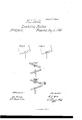
Letters Patent 4No. 80,942, elated August 11, 1868:
IMPROVEMENT IN Dorn-Tartine nncnmns.- i
@tu tlgrhnlt tentati in it tijentetta @anni nu mating putt ni tigt same.
TO ALL WHOM IT MAY GONCERN:
Be it known that I, Roscon J. GOULD, of'Newark, in the county of'Essex, and State of `New Jersey,1heve invented anew and improved Dove-Tailing Machine; and I'do'hereby declare the following to be a full, clear, and exact description thereof, which will enable thoseV skilled in the art to make and use the same, reference being had to the accompanying drawing, forming part of this specification, in which drawing-- A Figure 1 represents a transverse section of this invention.q l
Figure 2 is a plan or top view ofthe same. i
Figure 3 is a detached sectional view of one of the gauges. K
Figures 4, 5, 6, and? are diagrams illustrating the manner in which the saws cut.
Similar letters indicate corresponding parts. l
This invention relates to certain improvements v-in that classof dove-tailing machines in which t'wo sets of s saws are employed, one set for producing the tenons,landthe other the mortises or grooves.
The invention consists in cutting dove-tails from thel bottoms ofl the grooves, or of the spaces between the tencns, in such a manner that the distance between said bottoms becomes independent of the edges of theY boards, and said distance will be'true and correct, even if the opposite edges of a board should not be parallel; also, in the arrangement'of adjustable stops, secured to the upright gauges, and made in suchta shape that they can be brought to bear on the bottoms of`the grooves or spaces between the tenonsfand the operation of cutting the dove-tails-from the bottoms of the grooves or spaces is materially facilitated; further, in *thev arrangement of a' movable fulcrum, in combination with the swinging abutment, in such a manner that by adjusting the fulcruin, a certain motio'n transversely tothe carriage is imparted to `said abutment according t`o the desired width of the grooves or the spaces between the tenons; also, in the arrangement of a lining of wood, or other soft mhterial, in thc bottom edge of the abutment, in such a manner' that-the boards are snpport'ed close to the edges of the 'grooves or spaces between the tenons, without 'exposingthe cutting-edges ot` the saw to any injury, which they would be liable to sustain'if the metal .body of the abutment should bc made to extend clear down; further, in the arrangement of an upright gauge, provided. with arr adjustable slide in combination witha gang ofsaws in such a manner that Athe position of the board in'relaton to the saws can be readily adjusted; also, in the arrangement of two `upright gauges, provided with slides, in one and the same abutment, in such a manner Vthat the cutting of dove-tails from one and 'the same face or side ofthe boardis facilitated; further, in the arrangement of two stationary abutments extending across the carriage in diierent directions, and at angles which are supplements toY each other, said abutments being provided with upright gauges and slides in such a mannerthat by placing the boards 4successively against the abutments, the operation of cutting the dove-tails can be e'ected from one and the same side -orvface of' the boards.
t A represents a frame, which forms the bearings for two'shafts, B C, and whichis provided with two distinct guido-ways, a a, 6 b, as clearly shown Vin the drawing. A Y y On the shaft B is mounted a serios of saws, D, which serve to cut the grooves or mortises, and on the guide-ways a a is fitted thecarriage E, from which rise the gauges F F. l
The cutting-edges or faces of the saws1are oblique, or at an angle toward the longitudinal centre of their axio, and the gauges are so placed that their inner or working faces are' exactly at right angles'toy a line connecting the cutting-edges of the various saws. I
Each of the gauges lis provided with a slide, c, which can be move'd up or down in a slot, and which is securcd'in the desired position by a set-screw, d.
Each slide is provided with a slot, to receive al stop, e e', which is secured in the desired position'by a nut, f, screwingon the shank of the stop. By these means the strop can be adjusted up anddown by moving the slide in itslslot, and it can alsoibe set closer to Vor farther from the working face of, its gauge, to suit the work tobe produced.A i
The gauges F F are adjustable in their carriage E, according to the width of the board into which the grooves are to be cut, and the distance desired from the edge of the board tothe nearest groovc, and according to the desired width ofthe grooves. After tbc gauges have been thus adjusted, the slides c are set, so that the stops e and e are placed at the same distance from the top of the saws, and to correspond to the height or length of the board desired fromthe inside ofthe first row of grooves to be eut.. The board is placed withl one edge against the gauge F, with its upper end bearing against thestop e, and pushing the carriage forward, theboard is carried across thesaws, and a scriesof cuts is produced, such as shown in fig. 4.
. The board is then reversed, so thatthe same edge is against the gauge F that was against gauges F before, leaving the same'cnd up to bearagainst the stop e', and the board is carried againl'over the-saws, whereby the grooves on one end ofthe board are finished in the form shown in Eg.'5, where the letter o represents the first or old and letter 'a the second or new cut. After one end of the board has thus been provided with grooves or mortiscs, the board is turned upside down, and the stops e e are so adjusted that they will bear against the bottoms or inside of the grooves, as shown in fig. 1. The grooves at the opposite edge'ot` the board are then finished in the same manner as above described.
By bringing the stops e e to bear on the bottoms of the first row of grooves, the distance between these bottons and the bottoms of the grooves to beformed at the opposite end becomes absolutely the same in any number of boards, even if the boards should not all be sawed to the same length, while i-n cutting the grooves, as now practised, the gaugespor stops are always brought to bear on the end of the hoard to be cut, and if the two ends are not perfectly parallel, or the boards not of the same length, the distances between the bottoms .ofthe grooves of the two ends become unequal, and the lboxes or other work produced will not be square, whereas, if the distance between the bottoms of the grooves is made exact, as in my machine, the work necessarily becomes square, and the surplus` wood projecting beyond the edges can be readily planed off after the several boardshave 'been fitted together, as is done in making dove-tailed joints by hand, leaving the joints smooth and perfect, which would not be the case if the boards were nshed to the exact length before being'cut.
By having the gauges F F" at right angles to the cutting-line of the saws, and always working from the same edge of the board, the bottoms ofthe grooves will always be at right. angles with that edge, which would not be the case if the boards were' worked from the end which' is being cut, as is, gencrallylthe. way'now practised.
' For cutting the itenons,'I use a gang of saws, G, which are-mcunted on the shaft C. This shaft has its bearing in that position of the frame A which is provided with 'the guide-ways b 6, and on these guide-ways is tted-the carriage H. l
From this carriage rises the abutment I, which is provided with a slot, so that said gauge canbe adjusted to suit the width of the boards and thevdistance to be cut from the edge. The abutment I is either made sta.
tionary or movable. If made stationary, it is placed in an oblique position, to correspond to the shape of the tenons to be cut, and a second abutment, I', is provided, which extends across the carriage, at some distance from the iirsty abutment, in a different direction, at an angle with the guide-ways b b, which forms the supplement of the angle made by the abutment I andthe guideways b b. v From theabutment I rises the gauge J', and both gauges J and J are provided with adjustable slides c and stops c, as previously described.
The board to 'be cut is placed with one side or'face against the abutment I, itsA edge bearing against the gauge J, which has be'en previously adjusted to suit the width of board and position of the nearest cut, and.,
the stop e is brought to bear on the end of the board, at the proper distance from' the top of the saws, to give the desired depth of cut.'
.v By running the carriage over the saws, 'a series of cuts, p, is produced, as indicated in igf, then the carriage is run back, the boardisplaced against thel abutment I with the same side or face which rested against the upright gauge J, and the stop e of gauge J placed at some distance above the saws, as stop e, on gauge J', then, by passing the carriage again' over the saws, the tenons are finished. VIt' i-tis desired to make a cut wider than the saw, the upright gauge J may be placed in position from the first saw, to make the cut n as in the dotted lines, iig. 7, instead ofthe cut n.. v
The board is then turned upside down, with the same side or face presented to the abutment. And when the two edges of the board are not'parallel and truc, the gauges .I J may be moved to the opposite end of the` abutment, and at ythe same distance from the first saw en that side as .they were from the first saw on the other side. The stops e are each set at the same distance from the saws, and to bear on the bottoms of the spaces between the tenons previously eut at one end, and the""tenons at the opposite endfare cut in the same l manner-as above stated. Y
By bringing the stops e to bear on the bottoms ofthe spaces between the tenons, the distance 'between these bottoxnsis rendered absolutely equal, and independent of any irregularity lexisting in the lengths of the 1 boards, fand the work produced becomes square and correct.
` It must also be remarked, that in' my machine the tenons are finished from the same side o r face and edge of the board, so that their shape or size will not be inuenced by any irregularity in the edges, or by any inequality or variation in the thickness of the boards. l l
Instead of using two stationary abutments, I need use only one abutment, I', which in this case is secured to its carriage by a pivot, g. v
This pivot screws into a lugprojecting from the carriage, and it passes through a slot, h, in a lixg projecting from the abutment. The object of this slot is to enable the'operator-to adjust the fulcrum of the abutment, so that said abutment, on being swung on its pivot, will assume at the same time a slight motion transversely to the carriage, whereby the upright gauge I -is brought in the desired position, without the necessity of unscrewing said gauge and moving it in the abutment.- Thischange in the position of the gauge becomes necessary, in order to'produce `spaces of the desired width, 4as will-'be readily understood by referring to the diagram shown in iig?, wherepthe first cut -produced is indicated by the -letter o, andthe second cntfby the letter n. A l I i AIt' theV gauge has no transverse motion, the second cut takes out onlythe triangle t, and the width of the space at its narrow end'is equalto the width of thes'awgebut by imparting to the gauge a slight transverse motion, the second cut will be represented by dotted lines n', anda space of the desired width can thus be produced with ease and facility.
`The inclination of the movable abutment is determined by'the'adjustable stops S. The abutments I I are Vgenerally made `of-iron, and a lspace is cut out, at their bottom edges, to let the saws Apass freely. The wood to e o u have overcome by inserting into the edge of the abutment a lining, i, of woodV o r other soft material, which will not injure the saws it' the same should come-iu'contact therewith. This lining is provided with slots just wide be out is thus'not supportedclose to the saws, and the edges are liable to become rucrged. This diiiiculty -I enough to let the saws pass, and the edges 'of the-cuts produced become smooth and even. p The improvement of my machinewill'be seen by referring to the drawings on sheet 2.- Figs.`4 and 5 show the'boards with the mortiisesz" `:Byworking with IthesameA edge of thel board against the gauges` FF', and thestops e being at the same distance from the` saws,`the bottoms of the mortises oni-each end will be at right angles with the edge worked from, aud `their width at the bottomswill bethe same on both, and. also any num# ber of boards may be finished-to thefsame sise as to the nsideof bottoms of the mortises,leaving any surplus ot stuitV on'the outside of thebox-jor work to b e trimmed oft'.
This effect willrbe readilyunderstod by' referring to iig. 5, where the dotted lines show the irregularity ofthe e'dgeand theshape 'of themo'rtise produced in that case. The same is true of'the tenonsf/ By work. ing in -every operation from the same edge, thebottoms ot'V the grooves are at the same angle withV that edge voi the board. as the gauges are setto the saws, and by working from the same'iface, the thickness of the different boards, cannot aiect the size of the cut at the narrow. side, where they tit the morti'sed board; and again, by working from the bottoms of thecutsV onV the ends', any number of boards may bemade ot'Y the same distance between the bottoms, without'havling them sawied vto anexact length.
The sliding carriages, gauges, Ito., may be placed so as to have 'the work in a horizontal position to the saws, and the saws may be ou a'sliding carriage, and the work remain stationary when the cut is made.
The slides e, in the upright gaugesd J', may be'soconstructed that they:project beyond both edges vof said gauges, and in'this ease the gauges are, double acting, so that by'shifting the gauges in the abutments from ,one
side of the saws to theother, the tenons can be nished from the same face'and from'the same edge of the board;V whereas, if-the gauges remain on the same side of the saws, and the board is turned over, after the tenons in oue'edge thereof have been finished the tenons on'the opposite edge will be cut from the same 'face `of the bo`ard,but'uot from the same edget'rand, if the edges of the boards'are not'paralleh'the tenons will not'become correct, those on one edge being in this case' at right angles with one edge, and those on the opposite edge at right'angles with th@ opposite edge. This disadvantage is obvia'ted, bymy double-acting slide.
Havingy thus described my invention, what-I claim as new, and desire to secure by Letters Patent, is 1. The within-describedfmethod of cutting dove-tails, byworking from the bottoms ofthe grooves', or of the spaces between the tenons, consisting of' the adjustable stops e, vin the slides of the upright gauges' F J,
V or any equivalent'means whichwill produce the sameV result.
2. 'The ad'ustable sto se, extendimY down intol the i rooves" or s aces between Vthel tenons, and secured i J P s g P inthe' slides c,which are movahleup'a'nd down on the upright gauges F J, substantially-as and for the purpose 'Y lset forth. i i
3. `The ,slotted bracket h, in combination with the fnlcrum-pin giet' the swinging abutment I', substantially as and for the purposedescribed. l I Y 4.V The,V combination ofan abutment, I or I', with an upright gauge, F or'J, movable inone direction, and
provided with `a slide, c, which is movable in a direction atright angles to the motion of the' gauge, substantially as and forthe purpose set forth.
' 5. The double-acting vertically-movable slides c in the upright gauges .T J',substantially as andfor the purpose described. l i e e A 6. The arrangement of two abutments, I I', extending across the carriage in diderentdirectionaand at angles which are supplements to eaeh-other, 'said abutments being'provided with upright horizontally-adjustable gauges J J', and vertically-adjustable slides c, substantially as and for the purpose set forth.
This specication signed by me, this 16th day of March, 1868- Roscoe J. eoULD.
Witnesses:
l W.. HAUFF, v E. F.i K Asrauuuna.
Publications (1)
| Publication Number | Publication Date |
|---|---|
| US80942A true US80942A (en) | 1868-08-11 |
Family
ID=2150437
Family Applications (1)
| Application Number | Title | Priority Date | Filing Date |
|---|---|---|---|
| US80942D Expired - Lifetime US80942A (en) | gould |
Country Status (1)
| Country | Link |
|---|---|
| US (1) | US80942A (en) |
Cited By (1)
| Publication number | Priority date | Publication date | Assignee | Title |
|---|---|---|---|---|
| US20080013997A1 (en) * | 2005-03-17 | 2008-01-17 | Kabushiki Kaisha Toshiba | Heating apparatus, heating apparatus control method and noncontact thermal sensing device |
-
0
- US US80942D patent/US80942A/en not_active Expired - Lifetime
Cited By (1)
| Publication number | Priority date | Publication date | Assignee | Title |
|---|---|---|---|---|
| US20080013997A1 (en) * | 2005-03-17 | 2008-01-17 | Kabushiki Kaisha Toshiba | Heating apparatus, heating apparatus control method and noncontact thermal sensing device |
Similar Documents
| Publication | Publication Date | Title |
|---|---|---|
| US80942A (en) | gould | |
| US125282A (en) | Improvement in dovetailing-machines | |
| US362896A (en) | Foueth to dayid wilson and eben b | |
| US10844A (en) | Device foe tongtjihg and g-roovibtg lumber | |
| US83671A (en) | Improvement in mortising-and-tenoning machine | |
| US6339A (en) | Planiwg-machine | |
| US459095A (en) | easenau | |
| US624882A (en) | Spoke-finishing machine | |
| US691428A (en) | Wood-cutting machine. | |
| US436145A (en) | mcbean | |
| US400818A (en) | Rule-working machine | |
| US16108A (en) | photo-lit ho | |
| US335833A (en) | Do vetai ling-machine | |
| US1993A (en) | Manufacture of plows | |
| US125536A (en) | Improvement in machines for cutting loaf-sugar | |
| US167727A (en) | Improvement in dovetailing-machines | |
| US13184A (en) | Method of cutting straight or curved mortises | |
| US93519A (en) | Improvement in rabbeting-machine | |
| US67316A (en) | William kester | |
| US6294A (en) | Hazard knowles | |
| US356286A (en) | Machine for crosscutting wood | |
| US260019A (en) | Gage for sawing ellipses | |
| US46391A (en) | Improvement in machines for mortising plane-stocks | |
| US336130A (en) | Machine | |
| US156883A (en) | Improvement in machines for forming dovetails |