US8094184B2 - Stereoscopic two-dimensional display device - Google Patents
Stereoscopic two-dimensional display device Download PDFInfo
- Publication number
- US8094184B2 US8094184B2 US11/664,918 US66491805A US8094184B2 US 8094184 B2 US8094184 B2 US 8094184B2 US 66491805 A US66491805 A US 66491805A US 8094184 B2 US8094184 B2 US 8094184B2
- Authority
- US
- United States
- Prior art keywords
- image
- image display
- plane
- stereoscopic
- optical path
- Prior art date
- Legal status (The legal status is an assumption and is not a legal conclusion. Google has not performed a legal analysis and makes no representation as to the accuracy of the status listed.)
- Expired - Fee Related, expires
Links
Images


Classifications
-
- G—PHYSICS
- G02—OPTICS
- G02B—OPTICAL ELEMENTS, SYSTEMS OR APPARATUS
- G02B30/00—Optical systems or apparatus for producing three-dimensional [3D] effects, e.g. stereoscopic images
- G02B30/20—Optical systems or apparatus for producing three-dimensional [3D] effects, e.g. stereoscopic images by providing first and second parallax images to an observer's left and right eyes
- G02B30/34—Stereoscopes providing a stereoscopic pair of separated images corresponding to parallactically displaced views of the same object, e.g. 3D slide viewers
- G02B30/36—Stereoscopes providing a stereoscopic pair of separated images corresponding to parallactically displaced views of the same object, e.g. 3D slide viewers using refractive optical elements, e.g. prisms, in the optical path between the images and the observer
-
- G—PHYSICS
- G02—OPTICS
- G02B—OPTICAL ELEMENTS, SYSTEMS OR APPARATUS
- G02B30/00—Optical systems or apparatus for producing three-dimensional [3D] effects, e.g. stereoscopic images
- G02B30/20—Optical systems or apparatus for producing three-dimensional [3D] effects, e.g. stereoscopic images by providing first and second parallax images to an observer's left and right eyes
- G02B30/26—Optical systems or apparatus for producing three-dimensional [3D] effects, e.g. stereoscopic images by providing first and second parallax images to an observer's left and right eyes of the autostereoscopic type
- G02B30/27—Optical systems or apparatus for producing three-dimensional [3D] effects, e.g. stereoscopic images by providing first and second parallax images to an observer's left and right eyes of the autostereoscopic type involving lenticular arrays
-
- G—PHYSICS
- G02—OPTICS
- G02B—OPTICAL ELEMENTS, SYSTEMS OR APPARATUS
- G02B30/00—Optical systems or apparatus for producing three-dimensional [3D] effects, e.g. stereoscopic images
- G02B30/20—Optical systems or apparatus for producing three-dimensional [3D] effects, e.g. stereoscopic images by providing first and second parallax images to an observer's left and right eyes
- G02B30/34—Stereoscopes providing a stereoscopic pair of separated images corresponding to parallactically displaced views of the same object, e.g. 3D slide viewers
Definitions
- This invention relates to a stereoscopic two-dimensional image display device for displaying a two-dimensional image pseudo-stereoscopically by using a image transfer panel.
- the stereoscopic two-dimensional image display device includes a display unit 1 provided with an image display plane 1 a on which an image is displayed and an image transfer panel 3 arranged apart from the image display plane 1 a .
- the light emitted from the image display plane 1 a is imaged on an imaging plane 2 in the space opposite to the display unit 1 with respect to the image transfer panel 3 so that the two-dimensional image visually recognizable as a stereoscopic display by a viewer 100 is displayed pseudo-stereoscopically on the imaging plane (stereoscopic image displaying plane) 2 .
- an object of this invention is to provide a stereoscopic two-dimensional image display device which can facilitate seeing of the image on a peripheral region which may become difficult to see as the screen size increases, and can effectively employ the entire screen as an image display plane.
- the stereoscopic two-dimensional image display device defined in claim 1 comprises: a display unit provided with an image display plane on which an image is displayed; an image transfer panel arranged apart from the image display plane, for imaging light emitted from the image display plane on an imaging plane in a space, thereby displaying a stereoscopic two-dimensional image; and an optical path changing member arranged between the image display plane and the imaging plane, for changing the optical path of the light emitted from the peripheral edge having a predetermined region constituting the image display plane.
- FIG. 1 is a perspective view showing a schematic structure of a stereoscopic two-dimensional image display device according to the first embodiment of this invention.
- FIG. 2 is a view schematically showing that the image in the peripheral region on a screen can be seen even when a viewer approaches the screen to see in the above device.
- FIG. 3 is a view schematically showing the details of an image transfer panel 3 in the above display device.
- FIG. 4 is a front view for explaining the central region and peripheral region on a screen in the above device.
- FIG. 5 is a plan view showing a schematic structure of a first example of a stereoscopic two-dimensional image display device according to the second embodiment of this invention.
- FIG. 6 is a plan view showing a schematic structure of a second example of a stereoscopic two-dimensional image display device according to the second embodiment of this invention.
- FIG. 7 is a view schematically showing that the image in the peripheral region on a screen can be seen even when a viewer approaches the screen to see in the device according to the second embodiment.
- FIG. 8 is a view showing a prism which is an example of an optical path changing member.
- FIG. 9 is a view showing a prism sheet which is an example of the optical path changing member.
- FIG. 10 is a plan view of an example in which the optical path changing means is a prism.
- FIG. 11A is a front view showing an example in which an image for guidance is arranged; and FIG. 11B is a view showing a mark when a viewing position is not proper.
- FIG. 12 is a view showing a concrete display example in the embodiments of this invention.
- FIG. 13 is a view showing another display example.
- FIG. 14 is a schematic plan view showing the theoretic configuration of a conventional stereoscopic two-dimensional image display device.
- FIG. 15 is a plan view for explaining the relationship between a visual field angle and a proper viewing distance in a conventional stereoscopic two-dimensional image display device.
- FIG. 16 is a plan view for explaining the phenomenon that the image in a peripheral region cannot be seen because a viewer excessively approaches a screen.
- Reference numeral 1 shows a display unit
- Reference numeral 1 a shows an image display plane
- Reference numeral 2 shows an imaging plane
- Reference numeral 3 shows an image transfer panel
- Reference numeral 10 shows an light-diffusing member
- Reference numeral 20 shows an optical path changing member
- Reference numeral 22 shows a prism
- Reference numeral 23 shows a prism sheet.
- FIG. 1 is a perspective view showing a schematic structure of a stereoscopic two-dimensional image display device M 1 according to this embodiment.
- FIG. 2 is a view schematically showing that the image on the peripheral region on a screen is visible even when a viewer approaches the screen to see.
- FIG. 3 is a view schematically showing the details of an image transfer panel 3 .
- FIG. 4 is a front view for explaining the central region and peripheral region on a screen.
- a stereoscopic two-dimensional image display device M 1 includes a display unit 1 provided with an image display plane 1 a on which an image is displayed and an image transfer panel 3 arranged apart from the image display plane 1 a .
- the light emitted from the image display plane 1 a is imaged on an imaging plane 2 in the space opposite to the display unit 1 with respect to the image transfer panel 3 so that the two-dimensional image visually recognizable as a stereoscopic display by a viewer 100 is displayed pseudo-stereoscopically on the imaging plane (stereoscopic image displaying plane) 2 .
- a light diffusing member (optical-path changing member) 10 is arranged which diffuses the light emitted from the peripheral edge having a predetermined region constituting the image display plane 1 a.
- the light diffusing member 10 may be a diffusing plate, a diffusing sheet, a screen, etc.
- the light diffusing member 10 is arranged in the peripheral region exclusive of the central region of the imaging plane 2 .
- the light diffusing member 10 shaped in a square plate is employed, by hollowing out the central area thereof in the square shape, the light diffusing member 10 can be arranged in only the peripheral region.
- the stereoscopic two-dimensional image display device M 1 has a box 20 which houses a display device serving as the display unit 1 and the image transfer panel 3 . In the vicinity of an opening 20 a of the box 20 , the imaging plane 2 is established. Further, as the case may be, as required, a position sensor described later may be provided on the inner side of the wall 20 b in the vicinity of the opening plane 20 a of the box 20 . Further, the stereoscopic two-dimensional image display device M 1 includes a control system such as a display driving unit, a sensor driving unit, an image creating unit and a control unit.
- the display unit 1 is a display device provided on the one inside of the box 20 opposite to the opening plane 20 a , which is a liquid crystal display, an EL panel, or a CRT.
- the display unit 1 has an image display plane 1 a consisting of a plurality of pixels on the plane on the opening side of the box 20 . The light with a color and intensity corresponding to the image is emitted from each of the pixels.
- the image transfer panel 3 for example, as shown in FIG. 3 , consists of two micro-lens arrays 3 a , 3 b .
- Each micro-lens array 3 a , 3 b has a plurality of micro-convex lenses 5 adjacently to one another in an array on both sides of a transparent substrate 4 of glass or resin with excellent transparency.
- the optical axis of each of the micro-convex lenses 5 formed on the one side of each transparent substrate 4 agrees with that of each of the micro-convex lenses 5 formed on the other side of each transparent substrate 4 .
- the lens array plane is formed on any plane of the respective planes (total four planes) of the two lens arrays will be described, but the configuration of the micro-lens array should not be limited to such an embodiment.
- the image transfer panel 3 When the light corresponding to the image emitted from the image display plane 1 a of the display unit 1 is incident on the one plane of the image transfer panel 3 , the image transfer panel 3 emits this light from its other plane. The light thus emitted is imaged on the imaging plane 2 opposite to the image display plane 1 a and apart therefrom. A light collection imaged by the image transfer panel 3 corresponds to the image displayed on the image display plane 1 a . Namely, the image transfer panel 3 displays the image displayed on the image display plane 1 a onto the imaging plane (stereoscopic image display plane) 2 which is a stereoscopic two-dimensional plane.
- the imaging plane is a plane set virtually in the space, but not a substance.
- the imaging plane is a stereoscopic plane in the space defined according to the operating distance of the image transfer panel 3 .
- the image imaged on the imaging plane 2 is a two-dimensional image. However, if the image has a sense of depth, or the background image on the display unit 1 is black so that the contrast of an object in the image is emphasized, it looks like as if a three-dimensional (stereoscopic) image would be projected in the space from the viewer 100 on the front. Namely, the two dimensional image displayed on the imaging plane 2 is recognized as the image seen pseudo-stereoscopically (stereoscopic two-dimensional image) by the viewer 100 .
- the light diffusing member 10 is arranged on the peripheral region of the imaging plane 2 . Therefore, as seen from FIG. 2 , the light emitted from the peripheral region on the screen can be diffused with an angle larger than the original visual field angle ⁇ so that the visual field angle ⁇ ′ can be substantially increased. As a result, even when the viewer 100 approaches the imaging plane 2 (screen), the light diffused from the peripheral points can be reached the viewer 100 . Accordingly, the viewer 100 can see not only the image in the central region but also the image in the peripheral region outside thereof. Further, this can also solve the problem that the image is difficult to see as the screen size increases, thereby facilitating upsizing of the screen. Further, since the image on the peripheral region is made easy to see, the region inclusive of the peripheral region can be employed as an effective display screen with no waste.
- the direction of directivity is set nearer to the position where the viewer 100 stands (nearer to the center of the screen).
- the light emitted from the imaging plane 2 can be reached the viewer 100 with no waste so that a bright and clear image can be seen.
- the image displayed on the imaging plane 2 and recognized by the viewer 100 is formed by the light not passing through the light diffusing member 10 in the central region and the light passed through the light diffusing member 10 in the peripheral region. Therefore, difference in a seeing manner may occur between the central region 2 a and the peripheral region 2 b as shown in FIG. 4 . So, it is desirable to distinguish between the kinds of the image by displaying the main image such as a character or object in the central region 2 a and the subsidiary image such as an operating icon or an explanatory drawing in the peripheral region 2 b . Thus, a feeling of wrongness by the difference in the seeing manner between the central region 2 a and the peripheral region 2 b can be eliminated.
- the image extends over the central region 2 a and peripheral region 2 b , the possibility of feeling of wrongness may be increased. So, it is desirable to display a discontinuous segment (e.g. blank) of the image at the boundary between the central region 2 a and the peripheral region 2 b.
- a discontinuous segment e.g. blank
- FIGS. 5 and 6 are plan views showing the schematic configuration of a stereoscopic two-dimensional image display device M 2 according to this embodiment.
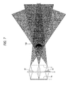
- FIG. 7 is a view schematically showing that the image on the peripheral region on a screen is visible even when a viewer approaches the screen to see.
- the stereoscopic two-dimensional image display device M 2 is characterized, as shown in FIGS. 5 and 6 , by the provision of an optical path changing member 20 located between the image display plane 1 a and the imaging plane 2 ; the optical path changing member 20 serving to bend the optical path of the light emitted from the peripheral edge having a predetermined region constituting the image display plane 1 a toward the center of the screen.
- the optical path changing member 20 may be located at any position between the image display plane 1 a and the imaging plane 2 . In the example illustrated in FIG. 5 , it is located in nearly intimate contact with the front surface of the image transfer panel 3 . In the example illustrated in FIG. 6 , it is located in nearly intimate contact with the rear surface of the image transfer panel 3 .
- the optical path changing member 20 may be a lens not shown (e.g. Fresnel lens), a prism 22 as shown in FIG. 8 , or a prism sheet 23 having an arrangement of a plurality of prisms 23 a , as shown in FIG. 9 .
- FIG. 10 illustrates an example in which the prism 22 is located in intimate contact with the rear surface of the image transfer panel 3 .
- the optical path changing member 20 in a shape of a square sheet is employed, by hollowing out the central area thereof in a square shape, the optical path changing member 20 can be arranged in only the peripheral region.
- FIG. 11A illustrates an example of image display for guidance.
- the image for guidance three marks 24 of ⁇ are arranged on the right and left sides of the peripheral region 2 b , respectively.
- the shape of the image for guidance should not be limited to ⁇ .
- the number of the marks 24 and their positions should not be limited to the example illustrated in FIG. 11A .
- ⁇ appears partially chipped or blurred. Where the viewing position is off to either right or left, the left side or right side of ⁇ appears partially chipped. Where the viewing position is off to either or left, the left side or right side of ⁇ appears partially chipped. Where the viewing position is off to back or forth, ⁇ appears blurred. When the viewer moves to the position where ⁇ appears clearly and round with no chip, the viewing position can be established as an appropriate position.
- the image for guidance may be displayed to be superposed on a normal image. Otherwise, the image for guidance may be previously displayed to urge the viewer to adjust the viewing position and thereafter eliminated to display the normal image.
- the optical path changing member 20 is located in the peripheral region of the front surface or rear surface of the image transfer panel 3 .
- the optical path of the light emitted from the peripheral region on the screen can be bent toward the center of the imaging plane 2 .
- the viewer 100 can see not only the image in the central region but also the image in the peripheral region outside thereof. Further, this can also solve the problem that the image is difficult to see as the screen size increases, thereby facilitating upsizing of the screen.
- the region inclusive of the peripheral region can be employed as an effective display screen with no waste.
- FIGS. 12 and 13 illustrate concrete examples displayed on the imaging plane 2 in the stereoscopic two-dimensional image display device M 1 , M 2 according to each of the first and second embodiments.
- the main image e.g. character image, object image
- the subsidiary image such as a frame decoration 28 or an explanation 29 is displayed.
- the main image is displayed whereas in the peripheral region 2 b , icon images of various operating buttons are displayed.
- the peripheral region 2 b in the example of FIG. 13 is constituted as a user interface region, when a user adds an a specific operating input at the position of the icon image corresponding to each of various instructions, he can give an instruction such as an image change.
- the user interface region in this case is a region sensed by a position detecting sensor described later.
- the control unit changes the image displayed in the central region 2 a according to an operation represented by the icon image displayed at the detected position.
- the position detecting sensor serves to detect the position of the object (to be detected) such as the user's finger inserted in a predetermined region thereby to produce a signal corresponding to the detected position.
- the position detecting sensor is located, for example, on the inner peripheral side of the opening of the box.
- the position detecting sensor may be a two-dimensional position detecting sensor or a three-dimensional position detecting sensor according to uses.
- the two-dimensional detecting sensor is adopted as the position detecting sensor, it is preferably constructed so that when the object such as a human's finger or a stick crosses a detecting plane of the imaging plane 2 or a plane in the vicinity thereof, the detected signal corresponding to the position is produced. Further, the control unit preferably changes, for example the main image displayed in the central region 2 a according to the signal produced from the position detecting sensor.
- the image of a pot is displayed in the central region 2 a of the imaging plane 2 .
- a plurality of icon images 31 to 44 are displayed as an operating menu so as to surround the pot image.
- the character of “expansion” encircled by a rectangle is shown like a button.
- the control unit changes the pot image so as to correspond to the meaning of the image of the character or symbol (“reduction”, “movement”, “rotation”, “color”, “illumination”, “opening”, “closing”, “ ⁇ ”, etc.) displayed on each of the icon images 32 to 44 .
- the icon image represented by the character has a button function for mode selection.
- “reduction” means the reduction of the size of the pot; and “movement” means if or not the mode of moving the displaying position of the pot should be adopted.
- the “rotation” means if or not the mode of rotating the pot image should be adopted.
- the “color” means changing the color scheme of the pot.
- the “illumination” means if or not the image of the pot as illuminated with light should be displayed, or changing the angle and direction of light illumination.
- the “opening” and “closing” means the operation of opening and closing the cap of the pot.
- the group of icons using symbol “ ⁇ ” correspond to the operations of actually moving or rotating the pot by manipulating these ions after the group of ions for mode selection such as the movement or rotation have been manipulated.
- the optical path changing member 10 is arranged for changing the optical path of the light emitted from the peripheral edge having a predetermined region constituting the image display plane 1 a .
- the light emitted from the peripheral region of the screen which was difficult to see when the viewer excessively approached the screen can be reached the viewer by the action of the optical path changing member 10 .
- the image in the peripheral region can be seen. Further, this can also solve the problem that the image is difficult to see as the screen size increases, thereby facilitating upsizing of the screen.
- the region inclusive of the peripheral region can be employed as an effective display screen with no waste.
- the optical path changing member 10 diffuses the light emitted from the peripheral edge of the image display plane 1 a , the visual field angle in the peripheral region of the screen can be substantially increased. As a result, even when the viewer approaches the imaging plane 2 , the light diffused from the peripheral region can be reached the viewer so that the image in the peripheral region can be seen.
- the optical path changing member 10 in this case may be the light diffusing member such as a diffusing plate, a diffusing sheet, a screen, etc.
- the optical path changing member 20 may be a member which bends the light emitted from the peripheral region on the screen toward the center of the image display plane. In this case, even when the viewer approaches the imaging plane 2 , the light emitted from the peripheral region can be reached the viewer so that the image in the peripheral region can be seen.
- the optical path changing member in this case may be a lens (Fresnel lens), a prism, or a prism sheet having an arrangement of a plurality of prisms.
- optical path changing member 20 may be arranged in the vicinity of the imaging plane 2 , or in the vicinity of the front surface or rear surface of the image transfer panel 3 .
Landscapes
- Physics & Mathematics (AREA)
- General Physics & Mathematics (AREA)
- Optics & Photonics (AREA)
- Testing, Inspecting, Measuring Of Stereoscopic Televisions And Televisions (AREA)
- Stereoscopic And Panoramic Photography (AREA)
Abstract
Description
- Patent Reference 1: JP-A-2001-255493
- Patent Reference 2: JP-A-2003-98479
- Patent Reference 3: JP-A-2002-77341
- Patent Reference 4: JP-A-2003-156712
Claims (5)
Applications Claiming Priority (3)
| Application Number | Priority Date | Filing Date | Title |
|---|---|---|---|
| JP2004295313 | 2004-10-07 | ||
| JP2004-295313 | 2004-10-07 | ||
| PCT/JP2005/017856 WO2006038509A1 (en) | 2004-10-07 | 2005-09-28 | Stereoscopic two-dimensional image display device |
Publications (2)
| Publication Number | Publication Date |
|---|---|
| US20080273083A1 US20080273083A1 (en) | 2008-11-06 |
| US8094184B2 true US8094184B2 (en) | 2012-01-10 |
Family
ID=36142586
Family Applications (1)
| Application Number | Title | Priority Date | Filing Date |
|---|---|---|---|
| US11/664,918 Expired - Fee Related US8094184B2 (en) | 2004-10-07 | 2005-09-28 | Stereoscopic two-dimensional display device |
Country Status (3)
| Country | Link |
|---|---|
| US (1) | US8094184B2 (en) |
| JP (1) | JP4555828B2 (en) |
| WO (1) | WO2006038509A1 (en) |
Cited By (1)
| Publication number | Priority date | Publication date | Assignee | Title |
|---|---|---|---|---|
| US20180252934A1 (en) * | 2016-12-28 | 2018-09-06 | Kt Corporation | Floating hologram apparatus |
Families Citing this family (8)
| Publication number | Priority date | Publication date | Assignee | Title |
|---|---|---|---|---|
| JP4955056B2 (en) * | 2007-03-30 | 2012-06-20 | パイオニア株式会社 | Image display device |
| JP5353770B2 (en) * | 2010-03-05 | 2013-11-27 | カシオ計算機株式会社 | Stereoscopic image observation apparatus, stereoscopic video display apparatus, and program |
| WO2012032842A1 (en) * | 2010-09-06 | 2012-03-15 | シャープ株式会社 | Display system and detection method |
| GB2508406B (en) * | 2012-11-30 | 2016-10-12 | Badejoko Oyenuga Adeyinka | Screen arrangement for viewing images and motion in 3D, without goggles or headgear |
| KR20140144617A (en) * | 2013-06-11 | 2014-12-19 | 광운대학교 산학협력단 | Apparatus for projecting space image |
| JP7570293B2 (en) * | 2021-06-30 | 2024-10-21 | マクセル株式会社 | Space-floating image display device |
| JP2023001956A (en) * | 2021-06-22 | 2023-01-10 | 三菱電機エンジニアリング株式会社 | Aerial video display device |
| WO2024204051A1 (en) * | 2023-03-31 | 2024-10-03 | 三井化学株式会社 | Non-contact input device |
Citations (14)
| Publication number | Priority date | Publication date | Assignee | Title |
|---|---|---|---|---|
| US4853769A (en) * | 1987-06-16 | 1989-08-01 | Massachusetts Institute Of Technology | Time multiplexed auto-stereoscopic three-dimensional imaging system |
| EP0631170A2 (en) | 1993-06-24 | 1994-12-28 | International Business Machines Corporation | Back-lighting system for transmissive display |
| US6128144A (en) * | 1996-12-02 | 2000-10-03 | Olympus Optical Co., Ltd. | Optical system for camera and camera apparatus |
| US6181475B1 (en) * | 1995-08-21 | 2001-01-30 | Olympus Optical Co., Ltd. | Optical system and image display apparatus |
| US20010022562A1 (en) | 2000-03-10 | 2001-09-20 | Masaru Ishikawa | Apparatus for displaying a stereoscopic two-dimensional image and method therefor |
| JP2002077341A (en) | 2000-09-01 | 2002-03-15 | Pioneer Electronic Corp | Communication terminal, and lens adaptor used for the communication terminal |
| JP2002328333A (en) | 2001-04-27 | 2002-11-15 | Sony Corp | Wavefront control type display device and imaging reproduction method |
| JP2003098479A (en) | 2002-07-30 | 2003-04-03 | Pioneer Electronic Corp | Image display device |
| JP2003156712A (en) | 2001-11-22 | 2003-05-30 | Pioneer Electronic Corp | Image display device |
| JP2003238812A (en) | 2000-09-25 | 2003-08-27 | Shinya Nabeshima | Prestressed porous asphalt |
| JP2003337382A (en) | 2002-05-17 | 2003-11-28 | Olympus Optical Co Ltd | Video display screen |
| US20040263698A1 (en) * | 2003-06-02 | 2004-12-30 | Hee Nam | Display device with capacity of displaying three-dimensional images |
| US6992718B1 (en) * | 1998-08-31 | 2006-01-31 | Matsushita Electric Industrial Co., Ltd. | Illuminating apparatus, display panel, view finder, video display apparatus, and video camera mounting the elements |
| US7489840B2 (en) * | 2003-04-18 | 2009-02-10 | International Business Machines Corporation | Optical link module, optical interconnection method, information processor including the optical link module, signal transfer method, prism and method of manufacturing the prism |
Family Cites Families (2)
| Publication number | Priority date | Publication date | Assignee | Title |
|---|---|---|---|---|
| JP3966753B2 (en) * | 2002-03-28 | 2007-08-29 | 株式会社東芝 | Stereoscopic image playback device |
| JP2004053714A (en) * | 2002-07-17 | 2004-02-19 | Fuji Xerox Co Ltd | Image fixing device and image fixing method |
-
2005
- 2005-09-28 US US11/664,918 patent/US8094184B2/en not_active Expired - Fee Related
- 2005-09-28 JP JP2006539242A patent/JP4555828B2/en not_active Expired - Fee Related
- 2005-09-28 WO PCT/JP2005/017856 patent/WO2006038509A1/en not_active Ceased
Patent Citations (18)
| Publication number | Priority date | Publication date | Assignee | Title |
|---|---|---|---|---|
| US4853769A (en) * | 1987-06-16 | 1989-08-01 | Massachusetts Institute Of Technology | Time multiplexed auto-stereoscopic three-dimensional imaging system |
| EP0631170A2 (en) | 1993-06-24 | 1994-12-28 | International Business Machines Corporation | Back-lighting system for transmissive display |
| JPH0756171A (en) | 1993-06-24 | 1995-03-03 | Internatl Business Mach Corp <Ibm> | Back light system for transmission type display |
| US5526146A (en) | 1993-06-24 | 1996-06-11 | International Business Machines Corporation | Back-lighting system for transmissive display |
| US6181475B1 (en) * | 1995-08-21 | 2001-01-30 | Olympus Optical Co., Ltd. | Optical system and image display apparatus |
| US6128144A (en) * | 1996-12-02 | 2000-10-03 | Olympus Optical Co., Ltd. | Optical system for camera and camera apparatus |
| US6992718B1 (en) * | 1998-08-31 | 2006-01-31 | Matsushita Electric Industrial Co., Ltd. | Illuminating apparatus, display panel, view finder, video display apparatus, and video camera mounting the elements |
| US20010022562A1 (en) | 2000-03-10 | 2001-09-20 | Masaru Ishikawa | Apparatus for displaying a stereoscopic two-dimensional image and method therefor |
| JP2001255493A (en) | 2000-03-10 | 2001-09-21 | Pioneer Electronic Corp | Stereoscopic two-dimensional image display device and image display method |
| JP2002077341A (en) | 2000-09-01 | 2002-03-15 | Pioneer Electronic Corp | Communication terminal, and lens adaptor used for the communication terminal |
| JP2003238812A (en) | 2000-09-25 | 2003-08-27 | Shinya Nabeshima | Prestressed porous asphalt |
| JP2002328333A (en) | 2001-04-27 | 2002-11-15 | Sony Corp | Wavefront control type display device and imaging reproduction method |
| JP2003156712A (en) | 2001-11-22 | 2003-05-30 | Pioneer Electronic Corp | Image display device |
| JP2003337382A (en) | 2002-05-17 | 2003-11-28 | Olympus Optical Co Ltd | Video display screen |
| JP2003098479A (en) | 2002-07-30 | 2003-04-03 | Pioneer Electronic Corp | Image display device |
| US7489840B2 (en) * | 2003-04-18 | 2009-02-10 | International Business Machines Corporation | Optical link module, optical interconnection method, information processor including the optical link module, signal transfer method, prism and method of manufacturing the prism |
| US20040263698A1 (en) * | 2003-06-02 | 2004-12-30 | Hee Nam | Display device with capacity of displaying three-dimensional images |
| US7139042B2 (en) * | 2003-06-02 | 2006-11-21 | Samsung Sdi Co., Ltd. | Display device with capacity of displaying three-dimensional images |
Cited By (2)
| Publication number | Priority date | Publication date | Assignee | Title |
|---|---|---|---|---|
| US20180252934A1 (en) * | 2016-12-28 | 2018-09-06 | Kt Corporation | Floating hologram apparatus |
| US10761342B2 (en) * | 2016-12-28 | 2020-09-01 | Kt Corporation | Floating hologram apparatus |
Also Published As
| Publication number | Publication date |
|---|---|
| JP4555828B2 (en) | 2010-10-06 |
| WO2006038509A1 (en) | 2006-04-13 |
| JPWO2006038509A1 (en) | 2008-07-31 |
| US20080273083A1 (en) | 2008-11-06 |
Similar Documents
| Publication | Publication Date | Title |
|---|---|---|
| US7956819B2 (en) | Stereoscopic two-dimensional image display device | |
| EP1909255B1 (en) | Image display device | |
| US8299980B2 (en) | Image display device | |
| JP4996681B2 (en) | Image display device | |
| US20100245345A1 (en) | Image display device | |
| JP5006587B2 (en) | Image presenting apparatus and image presenting method | |
| US20060170644A1 (en) | Image display unit | |
| US20170293380A1 (en) | Interface device with a touch screen and a control button | |
| US9883176B2 (en) | Display device | |
| JP2006004300A (en) | Input/output device and terminal device | |
| US8094184B2 (en) | Stereoscopic two-dimensional display device | |
| JP4963125B2 (en) | Stereoscopic image display system | |
| US20100007636A1 (en) | Image display device | |
| JPH1074267A (en) | Display control device and method | |
| WO2013161498A1 (en) | Display input device | |
| JP3927578B2 (en) | Display device | |
| JP4284158B2 (en) | Stereoscopic two-dimensional image display system and image display method | |
| US20070216601A1 (en) | Stereoscopic Two-Dimensional Image Display Apparatus | |
| JP7812283B2 (en) | aerial control device | |
| JPH0916312A (en) | Input device for stereoscopic image display device | |
| US20100007602A1 (en) | Image display device | |
| KR101308415B1 (en) | Image display device | |
| KR101926819B1 (en) | Pointing device using three dimensional virtual button | |
| US7292392B2 (en) | Apparatus and method for displaying stereoscopic two-dimensional image | |
| AU2012317467A1 (en) | Operation key and switch unit |
Legal Events
| Date | Code | Title | Description |
|---|---|---|---|
| AS | Assignment |
Owner name: PIONEER CORPORATION, JAPAN Free format text: ASSIGNMENT OF ASSIGNORS INTEREST;ASSIGNORS:TOMISAWA, ISAO;ISHIKAWA, MASARU;REEL/FRAME:020623/0192 Effective date: 20080131 |
|
| STCF | Information on status: patent grant |
Free format text: PATENTED CASE |
|
| FPAY | Fee payment |
Year of fee payment: 4 |
|
| AS | Assignment |
Owner name: ASUKANET COMPANY, LTD., JAPAN Free format text: ASSIGNMENT OF ASSIGNORS INTEREST;ASSIGNOR:PIONEER CORPORATION;REEL/FRAME:038794/0169 Effective date: 20160518 |
|
| AS | Assignment |
Owner name: PIONEER CORPORATION, JAPAN Free format text: CHANGE OF ADDRESS;ASSIGNOR:PIONEER CORPORATION;REEL/FRAME:039716/0490 Effective date: 20100625 |
|
| FEPP | Fee payment procedure |
Free format text: MAINTENANCE FEE REMINDER MAILED (ORIGINAL EVENT CODE: REM.); ENTITY STATUS OF PATENT OWNER: LARGE ENTITY |
|
| LAPS | Lapse for failure to pay maintenance fees |
Free format text: PATENT EXPIRED FOR FAILURE TO PAY MAINTENANCE FEES (ORIGINAL EVENT CODE: EXP.); ENTITY STATUS OF PATENT OWNER: LARGE ENTITY |
|
| STCH | Information on status: patent discontinuation |
Free format text: PATENT EXPIRED DUE TO NONPAYMENT OF MAINTENANCE FEES UNDER 37 CFR 1.362 |
|
| FP | Lapsed due to failure to pay maintenance fee |
Effective date: 20200110 |