TECHNICAL FIELD
The present disclosure relates to electronic devices having surface features. In particular, aspects of the present disclosure relate to mobile communication and/or computing devices having surface features.
BACKGROUND
Portable electronic devices (e.g., mobile phones, personal data assistants, laptops, etc.) are widely used today for communication and computing applications. Conventional portable electronic devices typically include generally flat exterior surfaces to reduce development and production cost. However, a user may have difficulty stably holding such an electronic device in a desirable position because the flat exterior surfaces typically cannot adequately accommodate contours of the user's fingers. The flat exterior surfaces can also reduce the mechanical strength of the electronic device because flat surfaces can readily transmit, instead of dispersing, applied forces. These limitations can reduce the user's satisfaction with operating the electronic device.
BRIEF DESCRIPTION OF THE DRAWINGS
FIGS. 1A-C are a front view, a side view, and a back view, respectively, of an electronic device configured in accordance with an embodiment of the disclosure.
FIG. 1D is a partially cross-sectional view of the electronic device in FIG. 1C taken along line A-A.
FIG. 1E is a partially cross-sectional view of the electronic device in FIG. 1C taken along line B-B.
FIG. 2 is a functional schematic view of internal components of the electronic device in FIGS. 1A-C, configured in accordance with an embodiment of the disclosure.
FIG. 3 is a perspective view of a user holding the electronic device in FIGS. 1A-C.
FIG. 4 is a side view of a user holding the electronic device in FIGS. 1A-C.
FIG. 5 is another perspective view of a user holding the electronic device in FIGS. 1A-C.
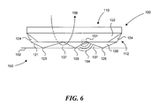
FIG. 6 is a side view of the electronic device in FIGS. 1A-C positioned on a support and configured in accordance with a further embodiment of the disclosure.
DETAILED DESCRIPTION
The present disclosure describes electronic devices having surface features and associated methods. Several of the details set forth below are provided to describe the following embodiments in a manner sufficient to enable a person skilled in the relevant art to make and use the disclosed embodiments. Several of the details and features described below, however, may not be necessary to practice certain embodiments of the disclosure. Additionally, the disclosure can include other embodiments that are within the scope of the claims but are not described in detail with respect to FIGS. 1-6.
Embodiments of an electronic device 100 having surface features are described below with reference to FIGS. 1A-C. FIG. 1A is a front view; FIG. 1B is a side view; and FIG. 1C is a back view of the electronic device 100. As illustrated in FIG. 1A, the electronic device 100 includes a housing 102 that can carry input components (e.g., a directional keypad 106 and input keys 109), output components (e.g., a display 104 and a speaker 108), and/or other communication/computing components generally found in PDA devices, cellular phones, laptop computers, tablet PCs, smart phones, hand-held email devices, and/or other mobile communication/computing devices.
Referring to FIG. 1A, FIG. 1B, and FIG. 1C together, the housing 102 can include a first portion 110 and a second portion 112 (e.g., a battery cover) proximate to the first portion 110. In certain embodiments, the first and second portions 110, 112 cooperate to form an enclosure having an internal cavity 111 that can accommodate a processor, an input circuitry, an output circuitry, a data storage device, and/or other electronic and/or mechanical components of the electronic device 100, as described in more detail below with reference to FIG. 2. In other embodiments, the housing 102 can also include at least one intermediate portion positioned between the first and second portions 110, 112 and/or other structural components to form the enclosure of the housing 102.
The first portion 110 can include a first end surface 113 at which the input components, output components, and/or other communication/computing components can be positioned, a plurality of first edges 116 (only one is shown for clarity) spaced apart from the first end surface 113, and a plurality of first side surfaces 114 extending between the first end surface 113 and the first edges 116. In the illustrated embodiment, the first end surface 113 is generally planar and substantially rectangular in shape, and the first side surfaces 114 extend generally perpendicularly from the first end surface 113. In other embodiments, at least one of the first end surface 113 and the first edges 116 can be curved, surface segmented, or otherwise nonplanar. In further embodiments, at least one of the first side surfaces 114 can be canted relative to the first end surface 113.
The second portion 112 can include a plurality of second edges 118 proximate to the first edges 116 of the first portion 110 and a second end surface 120 spaced apart from the second edges 118. The second end surface 120 is opposite to the first end surface 113. The first and/or second portions 110, 112 can include structural features to mate with one another at the first and second edges 116, 118. For example, the first and second portions 110, 112 can include corresponding grooves, channels, slots, holes, and/or other types of structural features at the first and second edges 116, 118 for coupling the first portion 110 to the second portion 112 via, e.g., compression. In other examples, the first and/or second portions 110, 112 can include a fastener, an adhesive, and/or another connecting mechanism for mutual connection. In the illustrated embodiment, the first and second edges 116, 118 are generally straight. In other embodiments, the first and second edges 116, 118 can have corresponding curves, canted angles, and/or other non-linear profile features. In a particular embodiment, the second portion 112 includes a battery cover for protecting a battery (not shown) held inside the internal cavity 111.
In certain embodiments, the second end surface 120 can be at least partially nonplanar. For example, as shown in FIGS. 1B-C, the second end surface 120 can include a plurality of generally planar surface segments 121 that are canted relative to one another and/or relative to the first end surface 113 (e.g., forming an angle of about 170° to about 180° relative to the first end surface 113). As a result, two adjacent surface segments 121 can intercept one another to form a boundary 123, and at least two boundaries 123 can intercept one another to form an apex 125 protruding from the second portion 112. As illustrated in FIG. 1C, the adjacent surface segments 121 intercept one another to form a plurality of boundaries 123 between each pair of the surface segments, and the plurality of boundaries 123 intercept one another to form three apexes 125 protruding from the second end surface 120. The boundaries 123 can be sharp or smooth. In the illustrated embodiment, the second end surface 120 has a substantially octagonal shape. In other embodiments, the second end surface 120 can also have a rectangular shape, a trapezoidal shape, a pentagonal shape, and/or other polygonal shape.
In the illustrated embodiment, individual surface segments 121 have a triangular shape or a tetragonal shape. In other embodiments, individual surface segments 121 can also have a rectangular shape, a trapezoidal shape, a pentagonal shape, and/or other polygonal shape. In yet other embodiments, at least some of the surface segments 121 can have a circular shape, a semicircular shape, and/or another at least partially curved shape. As a result, at least one of the boundaries 123 can be at least partially curved.
In further embodiments, in addition to or in lieu of the features of the embodiments discussed above, the second end surface 120 can also include at least one surface segment 121 that has a concave surface, a convex surface, and/or other curved surface. In other embodiments, some of the surface segments 121 can be generally planar and parallel to the first end surface 113. In yet further embodiments, all of the surface segments 121 are generally co-planar with one another so that the second end surface 120 is generally planar.
The second portion 112 can also include a plurality of second side surfaces 122 (four are shown for illustration purposes) extending between the second end surface 120 and the second edges 118. In certain embodiments, individual second side surfaces 122 can be canted, for example, by forming an angle A (as shown in FIG. 1E) of about 110° to about 130°, preferably about 115° to about 125°, relative to the second end surface 120. Each of the second side surfaces 122 can form generally the same or a different angle with the second end surface 120. In other embodiments, the second side surfaces 122 can be generally planar relative to the first side surface 114. In further embodiments, the second side surfaces 122 can be omitted, and the nonplanar second end surface 120 can extend substantially to the second edges 118. In yet further embodiments, the second side surfaces 122 can be convex, concave, and/or otherwise curved.
In the illustrated embodiments, the second portion 112 optionally includes at least one corner surface 124 (four are shown for illustration purposes) intercepting the second end surface 120, the second side surfaces 122, and the second edges 118. Each of the corner surfaces 124 extends from the second end surface 120 to an intersection 118 a formed by two adjacent second edges 118. The corner surfaces 124 can be generally planar or curved. In the illustrated embodiment, the corner surfaces 124 have a triangular shape and form an angle B of about 140° to about 160°, preferably about 145° to about 155°, relative to the second end surface 120. In other embodiments, the corner surfaces 124 can also have a tetragonal shape and/or other polygonal shape.
FIG. 2 is a functional schematic view of internal components of the electronic device 100 in FIGS. 1A-C. As shown in FIG. 2, the electronic device 100 can include an input circuitry 210, an output circuitry 212, a processor 214, and a storage 216 operatively connected to one another. At least some of these components can be housed in the internal cavity 111 of the housing 102. The input circuitry 210 can include analog and/or digital signal controllers for sampling input signals from, e.g., the directional keypad 106 (FIG. 1), the input keys 109 (FIG. 1), and/or other input components of the electronic device 100.
The processor 214 can include a microelectronic logic processor for processing signals supplied by the input circuitry 210 according to instructions stored in the storage 216, and outputting results to the output circuitry 212. A suitable processor 214 can include an OMAP 850 processor supplied by Texas Instruments of Dallas, Tex., running a Windows Mobile® 6.0 operating system supplied by Microsoft Corporation of Redmond, Wash.
The output circuitry 212 can include circuits and/or controllers for converting signals from the processor 214 to those suitable for output at, e.g., the speaker 108 (FIG. 1), the display 104 (FIG. 1), and/or other output components. For example, the output circuitry 212 can include an LCD display controller for controlling the display 104.
The storage 216 can include a hard drive, a flash ROM, an EPROM, and/or another suitable persistent computer-readable medium for storing instructions, records, and other data. For example, instructions for processing user input can be stored in the storage 216. These instructions can be at least partially incorporated into the operating system or can be an independent application.
Embodiments of the electronic device 100 can enable a user to stably and comfortably operate the electronic device 100. For example, as illustrated in FIG. 3, the corner surfaces 124 can provide a stable platform for a user 130 to comfortably rest index fingers 132 of the user 130. The corner surfaces 124 and/or the second side surfaces 122 can also allow the index fingers 132, the middle fingers 133, the ring fingers 134, and/or the little fingers 135 of the user 130 to rest naturally when the user 130 holds the electronic device 100 by forming a specific angle that at least partially corresponds to a particular viewing angle of the user 130. Further, as illustrated in FIG. 4, the corner surfaces 124 can also be configured to conform to the contours of the index finger 132, the ring finger 134, and/or other fingers of the user 130 and thus to provide improved comfort when holding the electronic device 100.
In certain embodiments, the second end surface 120 can guide the fingers of the user 130 via tactility. For example, as illustrated in FIG. 5, the electronic device 100 can optionally include a camera 127 carried by the housing 102 and having a lens 129 proximate to the second end surface 120. The user 130 can touch the second end surface 120 and recognize a position of his fingers relative to the lens 129 by sensing the boundaries 123 separating individual surface segments 121 and/or at least one apex 125. As a result, the user 130 can avoid touching the lens 129 and/or other components of the electronic device 100 when operating the electronic device 100.
In other embodiments, the second end surface 120 can also improve the stability of the electronic device 100 when placed on a support. FIG. 6 is a side view of the electronic device 100 in FIGS. 1A-C positioned on a support 150 having a generally planar support surface 152. As shown in FIG. 6, when the electronic device 100 is placed on the support 150, only the apexes 125 (three are shown for illustration purposes) contact the support surface 152. The three apexes 125 can enable the electronic device 100 to be stably placed on the support surface 152, and can allow the surface segments 121 extending from the apexes 125 not to contact the support surface 152. As a result, the friction between these surface segments 121 and the support surface 152 can be at least reduced or even avoided, thus reducing the risk of damaging the surface segments 121 and/or other components proximate to the surface segments 121 (e.g., the lens 129 shown in FIG. 5). In some embodiments, the apexes 125 can also be reinforced with rubber, plastic, metal, glass, and/or other material with sufficient strength to improve the structural integrity of the electronic device 100.
The second end surface 120 can also improve cooling the electronic device 100 during operation. As illustrated in FIG. 6, contacting the support surface 152 can create air gaps 137 between the support surface 152 and the second end surface 120 of the electronic device 100. The air gaps 137 can allow cooling air (as indicated by an arrow 156) to flow between the electronic device 100 and the support surface 152. The cooling air can carry away heat generated by the electronic device 100 during operation via convection, conduction, and/or radiation. As a result, the electronic device 100 can have improved heat dissipation and performance by having the second end surface 120.
Embodiments of the electronic device 100 with the second end surface 120 can also have improved acoustic performance. In certain embodiments, the electronic device 100 can optionally include a sound generator 151 (e.g., a ringer) and/or other acoustic components disposed at least proximate to the second end surface 120. During operation, the air gaps 137 can allow sound waves 154 to easily propagate from the sound generator 151 with at least reduced attenuation and/or interference from the support surface 152, thus improving acoustic performance of the electronic device 100.
From the foregoing, it will be appreciated that specific embodiments of the disclosure have been described herein for purposes of illustration but that various modifications may be made without deviating from the disclosure. Certain aspects of the disclosure described in the context of particular embodiments may be combined or eliminated in other embodiments. Further, while features associated with certain embodiments of the disclosure have been described in the context of those embodiments, other embodiments may also possess such features, and not all embodiments need necessarily the same features to fall within the scope of the disclosure. Accordingly, the disclosure is not limited except as by the appended claims.