BACKGROUND
1. Technical Field
The present disclosure relates generally to viewing devices, and more particularly to a device providing plural views of a person or object simultaneously.
2. Description of Related Art
Mirrors are most commonly used for personal grooming, decoration, and architecture. Typically, if a person wants to see both his front and back at the same time, he must use two or more mirrors inclined relative to one another (also called face-to-face mirrors) to generate multiple reflections. However, the typical structure or arrangement of face-to-face mirrors is bulky and inconvenient.
Therefore, what is needed is a plural-view device to overcome the above-described deficiencies.
BRIEF DESCRIPTION OF THE DRAWINGS
FIG. 1 is a schematic view of a plural-view device in accordance with a first embodiment, the plural-view device including a support rod, a camera module, and a power supply.
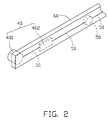
FIG. 2 is an enlarged, schematic view of the camera module and part of the support rod of FIG. 1, showing a power supply in the support rod.
FIG. 3 is a schematic view of a plural-view device in accordance with a second embodiment.
DETAILED DESCRIPTION
Referring to FIGS. 1 and 2, a plural-view device 100 according to a first embodiment is shown. The plural-view device 100 includes a frame 10, a plane mirror 20, a display panel 30, a camera module 40, a power supply 50, and a support rod 60. In this description, unless the context indicates otherwise, a “plane mirror” means a mirror that is physically substantially flat, regardless of the type of reflected image or images that the mirror is capable of displaying.
The frame 10 includes a first frame body 101 and a second frame body 102. The plane mirror 20 and the display panel 30 are respectively enclosed in the first frame body 101 and the second frame body 102. In the first embodiment, the first frame body 101 and the second frame body 102 are rectangular, and the first frame body 101 is pivotably connected with the second frame body 102. In particular, the second frame body 102 is rotatable in a first direction onto the first frame body 101. In this way, the first and second frame bodies 101, 102 are sandwiched together parallel to each other, such that the plural-view device 100 has a collapsed configuration. Furthermore, the second frame body 102 can be rotated in a second direction opposite to the first direction so that the second frame body 102 is sandwiched together with the first frame body 101 at a backside of the first frame body 101. In this way, the second frame body 102 is stowed or hidden behind the first frame body 101 when desired.
The display panel 30 is an electronic paper (e-paper), a digital frame, or other display device. In the exemplary embodiment, the display panel 30 is an e-paper. The e-paper typically includes a rewritable display panel and a flexible substrate. The e-paper is considered to be more convenient and comfortable to read than conventional displays. This is due to the e-paper having a stable image and a wide viewing angle, and being lightweight.
The camera module 40 is connected to the frame 10 via the support rod 60. The power supply 50 is configured for supplying electrical power to the display panel 30 and the camera module 40. In the exemplary embodiment, the power supply 50 is a battery. The support rod 60 can be moved toward or away from the frame 10. That is, the support rod 60 is adjustable about either or both of the plane mirror 20 and the display panel 30, for adjusting a field of view of the camera module 40. The support rod 60 may be a flexible rod, or an extension rod, or a combination of a flexible rod and an extension rod. The support rod 60 also may be a rigid rod pivotably connected with the frame 10, as illustrated.
In the illustrated embodiment, the camera module 40 is attached to a distal end of the support rod 60. The other end of the support rod 60 is pivotably connected to a middle portion of one vertical side border 103 of the second frame body 102 via a fastener such as a bolt 12. That is, the bolt 12 interconnects the support rod 60 and the side border 103. Two grooves 13 are defined in the same side border 103 symmetrically about the bolt 12. The grooves 13 are configured to selectively receive the camera module 40 when the support rod 60 is rotated to be parallel with the side border 103.
Referring to FIG. 2, the camera module 40 includes an image capture module 401 and a processing module 402. The power supply 50 is mounted in the support rod 60. The image capture module 401, the processing module 402, the power supply 50, and the display panel 30 are electrically connected to each other via a conducting wire 51. The image capture module 401 may be a charge coupled device (CCD) or a complementary metal oxide semiconductor (CMOS). When a person 300 stands facing the mirror 20, the camera module 40 can be positioned to take an image of the person's back by adjusting the support rod 60. After being processed by the processing module 402, the captured image is displayed on the display panel 30. Thus, the person 300 can see both front and back views in the plural-view device 100 simultaneously. It is to be understood that the position of the support rod 60 on the frame 10 is not limited to the position described above or illustrated in FIG. 1. The support rod 60 may be pivotably mounted at any suitable position of the frame 10. Furthermore, if the support rod 60 is a flexible rod, an end of the support rod 60 may be fixedly connected to the frame 10.
In an alternative embodiment, the plane mirror 20 may be provided in the second frame body 102, and the display panel 30 may be provided in the first frame body 101. With such a configuration, the person 300 can see both front and side views in the plural-view device 100 simultaneously. In another alternative embodiment, the plane mirror 20 may instead be a nonplanar kind of mirror.
Referring to FIG. 3, a plural-view device 200 according to a second embodiment is shown. The plural-view device 200 includes a frame 10 a, a plane mirror 20 a, a display panel 30 a, a camera module 40 a, a power supply (not shown), and a support rod 60 a. The frame 10 a includes a first frame body 101 a and a second frame body 102 a. The plane mirror 20 a and the display panel 30 a are respectively enclosed in the first frame body 101 a and the second frame body 102 a. The structure of the plural-view device 200 is similar to that of the plural-view device 100 of the first embodiment. One difference is that a slot 104 is defined in a top side border 103 a of the second frame body 102 a, and a block (not shown) protrudes out from the backside of one top corner of the first frame body 101 a. The block is movably engaged in the slot 104, allowing the first frame body 101 a to slide relative to the second frame body 102 a along the extending direction of the slot 104. The second frame body 102 a can thus be hidden behind the first frame body 101 a when desired. Another difference is that the support rod 60 a is pivotably connected to a middle portion of one horizontal side border 103 a. Thus, a person (not labeled) can see both front and top views in the plural-view device 200 simultaneously. Furthermore, it is to be understood that the position of the support rod 60 a on the frame 10 a is not limited to the position described above or illustrated in FIG. 3.
While preferred or exemplary embodiments have been described, the embodiments can be modified within the spirit and scope of this disclosure. This disclosure is intended to cover any variations, uses, or adaptations of the embodiments using the general principles of the invention as claimed. Further, this disclosure is intended to cover such departures from the present embodiments as come within known or customary practice in the art to which the invention pertains and which fall within the limits of the appended claims or equivalents thereof.