US8083253B1 - Shopping cart assembly with folding legs - Google Patents

Shopping cart assembly with folding legs Download PDF

Info

Publication number
US8083253B1
US8083253B1 US12/326,870 US32687008A US8083253B1 US 8083253 B1 US8083253 B1 US 8083253B1 US 32687008 A US32687008 A US 32687008A US 8083253 B1 US8083253 B1 US 8083253B1
Authority
US
United States
Prior art keywords
basket
framework
rollers
vehicle
cart assembly
Prior art date
Legal status (The legal status is an assumption and is not a legal conclusion. Google has not performed a legal analysis and makes no representation as to the accuracy of the status listed.)
Active, expires
Application number
US12/326,870
Inventor
Jill Butler
Current Assignee (The listed assignees may be inaccurate. Google has not performed a legal analysis and makes no representation or warranty as to the accuracy of the list.)
Individual
Original Assignee
Individual
Priority date (The priority date is an assumption and is not a legal conclusion. Google has not performed a legal analysis and makes no representation as to the accuracy of the date listed.)
Filing date
Publication date
Application filed by Individual filed Critical Individual
Priority to US12/326,870 priority Critical patent/US8083253B1/en
Application granted granted Critical
Publication of US8083253B1 publication Critical patent/US8083253B1/en
Active legal-status Critical Current
Adjusted expiration legal-status Critical

Links

Images

Classifications

    • BPERFORMING OPERATIONS; TRANSPORTING
    • B62LAND VEHICLES FOR TRAVELLING OTHERWISE THAN ON RAILS
    • B62BHAND-PROPELLED VEHICLES, e.g. HAND CARTS OR PERAMBULATORS; SLEDGES
    • B62B3/00Hand carts having more than one axis carrying transport wheels; Steering devices therefor; Equipment therefor
    • B62B3/02Hand carts having more than one axis carrying transport wheels; Steering devices therefor; Equipment therefor involving parts being adjustable, collapsible, attachable, detachable or convertible
    • B62B3/027Hand carts having more than one axis carrying transport wheels; Steering devices therefor; Equipment therefor involving parts being adjustable, collapsible, attachable, detachable or convertible collapsible shopping trolleys
    • BPERFORMING OPERATIONS; TRANSPORTING
    • B62LAND VEHICLES FOR TRAVELLING OTHERWISE THAN ON RAILS
    • B62BHAND-PROPELLED VEHICLES, e.g. HAND CARTS OR PERAMBULATORS; SLEDGES
    • B62B5/00Accessories or details specially adapted for hand carts
    • B62B5/0003Adaptations for loading in or on a vehicle
    • BPERFORMING OPERATIONS; TRANSPORTING
    • B62LAND VEHICLES FOR TRAVELLING OTHERWISE THAN ON RAILS
    • B62BHAND-PROPELLED VEHICLES, e.g. HAND CARTS OR PERAMBULATORS; SLEDGES
    • B62B2203/00Grasping, holding, supporting the objects
    • B62B2203/70Comprising means for facilitating loading or unloading
    • B62B2203/74Comprising means for facilitating loading or unloading rolling means, e.g. rollers
    • BPERFORMING OPERATIONS; TRANSPORTING
    • B62LAND VEHICLES FOR TRAVELLING OTHERWISE THAN ON RAILS
    • B62BHAND-PROPELLED VEHICLES, e.g. HAND CARTS OR PERAMBULATORS; SLEDGES
    • B62B2206/00Adjustable or convertible hand-propelled vehicles or sledges
    • B62B2206/02Adjustable or convertible hand-propelled vehicles or sledges adjustable in length or width
    • BPERFORMING OPERATIONS; TRANSPORTING
    • B62LAND VEHICLES FOR TRAVELLING OTHERWISE THAN ON RAILS
    • B62BHAND-PROPELLED VEHICLES, e.g. HAND CARTS OR PERAMBULATORS; SLEDGES
    • B62B2206/00Adjustable or convertible hand-propelled vehicles or sledges
    • B62B2206/06Adjustable or convertible hand-propelled vehicles or sledges adjustable in height

Definitions

  • the present invention relates to wheeled carts that have legs that can be folded into a retracted position. More particularly, the present invention relates to wheeled carts that are designed to collapse so that the cart can be placed inside a vehicle without being unloaded.
  • a shopping cart is typically obtained by a customer as that customer enters a store. The customer shops and places the various products into the cart. The cart is then used to wheel the products to the checkout counter. Once purchased and packaged, the packaged goods are placed back into the shopping cart and are wheeled to the buyer's car. The packaged goods must then be lifted out of the shopping cart and placed into the buyer's car. Finally, the shopping cart must be returned. After the buyer drives the packaged goods home, the buyer must manually carry the packaged goods out of the car.
  • Such people typically rely upon the use of collapsible portable carts. Such carts fold up and collapse into small shapes that can be easily loaded into an automobile. However, such collapsible carts cannot be folded up while still loaded with groceries. Accordingly, a person must unload the packages from the cart at the vehicle, fold and store the cart, drive home, unfold the cart and reload the cart.
  • the present invention is a folding shopping cart assembly.
  • the shopping cart assembly has a basket with a bottom surface and side walls.
  • a plurality of rollers are coupled to the basket, wherein said basket is capable of rolling upon those rollers.
  • a framework is provided for supporting the basket at an elevated height.
  • the basket is capable of moving on the rollers relative the framework between a retracted position, where most of the rollers are in contact with said framework, and a cantilevered position, where most of the rollers are not in contact with the framework.
  • Wheels are coupled to the framework so that the framework and the basket can be rolled together as a cart.
  • the cart assembly is rolled to the open bay of a vehicle.
  • the basket is extended into its cantilevered position, wherein the basket is extended into the vehicle.
  • the framework can be rotated up and around the basket. This causes the cart assembly to become compact so that it can be closed inside the vehicle.
  • the cart can be unfolded out of the vehicle by reversing the loading procedure.
  • the cart assembly can therefore be loaded and unloaded from a vehicle without any lifting, while the basket of the cart assembly remains full.
  • FIG. 1 is a perspective view of an exemplary embodiment of a shopping cart assembly
  • FIG. 2 is an exploded view of the shopping cart assembly shown in FIG. 1 ;
  • FIG. 3 is a side view of the shopping cart assembly having a basket in a retracted position
  • FIG. 4 is a side view of the shopping cart assembly having a basket in a cantilevered position
  • FIG. 5 shows the shopping cart assembly in a folded configuration and loaded into an automobile.
  • the cart assembly 10 includes a basket 12 .
  • the basket 12 can have a fixed size, the basket 12 of the exemplary embodiment is adjustable in size.
  • the basket 12 is comprised of two or more overlapping sections.
  • two sections 13 , 14 are shown for the sake of simplicity.
  • Each section 13 , 14 is comprised of a lattice base 15 and latticed walls 16 that extend upwardly from three sides of the base 15 .
  • One basket section 13 is slightly smaller than the other basket section 14 .
  • the two basket sections 13 , 14 overlap, with the smaller basket section 13 passing into the larger basket section 14 .
  • This configuration enables the configuration of the overall basket 12 to have a length L 1 that can be selectively altered.
  • the basket 12 is adjustable in length, but otherwise rigid.
  • the latticed walls 16 of the basket 12 may be hinged so as to be collapsible when not in use.
  • the width W 1 of the basket 12 can also be made to be adjustable.
  • a framework 20 is provided to support the basket 12 .
  • the framework 20 is supported by wheels 22 .
  • the wheels 22 can be fixed wheels or caster wheels.
  • the wheels can be different sizes. In the exemplary embodiment, wheels of uniform size are illustrated for the sake of simplicity.
  • the framework 20 has two side sections 24 , 25 wherein the basket 12 is interposed between the two side sections 24 , 25 .
  • Each of the two side sections 24 is preferably adjustable in height.
  • the two side sections 24 , 25 are interconnected by a plurality of telescoping supports 26 .
  • the telescoping configuration of the supports 26 enables the supports 26 to expand or contract when the basket 12 is enlarged or shortened.
  • At least one locking mechanism 28 is provided on at least one of the telescoping supports 26 .
  • the locking mechanism 28 is used to lock the two side sections 24 , 25 of the framework 20 at a fixed distance apart. This selectively sets the basket 12 at a fixed length L 1 .
  • the two side sections 24 , 25 of the framework 20 are generally C-shaped, wherein each has a horizontal top rail 30 , a horizontal bottom rail 32 and an adjustable vertical rail 34 that connects the two horizontal rails 30 , 32 together.
  • the basket 12 is interconnected with the horizontal top rails 30 of the two side sections 24 , 25 of the framework 20 . However, the interconnection is not fixed. Rollers 36 are mounted to the basket 12 . The rollers 36 engage tracks formed in or on the horizontal top rails 30 . This enables the basket 12 to move relative the framework 20 . The basket 12 can move between a fully retracted position and a cantilevered position, as will be further explained.
  • FIG. 3 and FIG. 4 the retracted position and the cantilevered position of the basket 12 are respectively shown.
  • FIG. 3 it can be seen that when the basket 12 is in its fully retracted position, most, if not all, of the rollers 36 are in direct contact with the horizontal top rails 30 .
  • FIG. 4 it can be seen that when the basket 12 is extended into its cantilevered position, the basket 12 extends away from the framework 20 as a cantilever and most of the rollers 36 do not contact the horizontal top rails 30 .
  • the rollers 36 on the basket 12 enable the basket 12 to move from a fully retracted position ( FIG. 3 ) to a fully extended cantilevered position ( FIG. 4 ) when the basket 12 is pulled forward in the direction of arrow 38 .
  • rollers 36 on the sides of the basket 12 are exposed.
  • the exposed rollers can roll onto the bed of a vehicle and help the basket roll into a vehicle.
  • one or more rollers may be placed under the middle sections of the basket 12 to help support the weight of the basket 12 inside a vehicle.
  • FIG. 4 a vehicle with a flat bed is shown. Not all vehicles have flat beds. Rather, some have wells and other uneven structures.
  • a cart assembly can be customized to a specific vehicle type. Collapsible supports can be made to automatically extend from the bottom of the basket to compensate for vehicle with uneven beds. Regardless to the vehicle type, what is important is that the basket 12 can be pushed on rollers into the bed of a vehicle without having to lift the weight of the basket 12 .
  • Two pivot pins 40 ( FIG. 2 ) are provided at opposite bottom corners of the basket 12 .
  • the pivot pins 40 engage the top rails 30 of the framework 20 only when the basket 12 is in its extended cantilevered position, such as is shown in FIG. 4 .
  • the framework 20 can be rotated about the pivot pins 40 . Once rotated, the wheels 22 that once faced downward are inverted so that they now face upward. The side sections 24 , 25 of the framework 20 rotate into positions along the sides of the basket 12 . The overall cart assembly 10 therefore becomes far more compact without affecting the size of the basket 12 or the contents of the basket 12 .
  • the wheels may be removable or foldable to further reduce space.
  • the side sections 24 , 25 of the framework 20 can be made further collapsible to further reduce size.
  • FIGS. 2 through 5 the operation of the cart assembly 10 will now be understood.
  • the basket 12 is filled with products to be purchased.
  • the vehicle is a hatchback, SUV, or similar vehicle that has a rear door.
  • the cart assembly 10 is wheeled to the rear of the vehicle.
  • the framework 20 has been previously adjusted in height to match the requirements of the vehicle.
  • the basket 12 is then pulled forward to its cantilevered position. Once the basket 12 is in the cantilevered position, the entire cart assembly 10 is pushed toward the vehicle until the basket 12 enters the vehicle. Once in the vehicle, the rollers 36 on the bottom of the basket 12 rest upon the interior of the vehicle.
  • the framework 20 can be rotated up and around the basket 12 .
  • the basket 12 and the entire framework 20 are now supported by the basket rollers 36 .
  • the folded cart assembly 10 can then be pushed on the rollers 36 further into the interior of the vehicle.
  • the rear door of the vehicle is then closed and the vehicle is ready to be driven.
  • the cart assembly 10 in its folded configuration ( FIG. 5 ) is manipulated into its unfolded configuration ( FIG. 4 ) by rotating the framework 20 back onto the ground.
  • the basket 12 in its cantilever position ( FIG. 4 ) is then moved to its retracted position ( FIG. 3 ).
  • the cart assembly 10 can then be rolled away from the vehicle without ever having to unload the basket 12 .

Abstract

A folding shopping cart assembly having a basket with a bottom surface and side walls. A plurality of rollers are coupled to the basket. A framework is provided for supporting the basket at an elevated height. The basket is capable of moving on rollers relative the framework between a retracted position, where most of the rollers are in contact with the framework, and a cantilevered position, where most of the rollers are not in contact with the framework. Wheels are coupled to the framework so that the framework and the basket can be rolled together as a cart. The framework can be rotated about the basket to a stowed position that enables the cart assembly to be placed in a vehicle.

Description

RELATED APPLICATIONS
This application is a continuation-in-part of U.S. Provisional Patent Application No. 61/004,924, entitled SHOPPING CART ASSEMBLY WITH FOLDING LEGS, filed Dec. 3, 2007.
BACKGROUND OF THE INVENTION
1. Field of the Invention
In general, the present invention relates to wheeled carts that have legs that can be folded into a retracted position. More particularly, the present invention relates to wheeled carts that are designed to collapse so that the cart can be placed inside a vehicle without being unloaded.
2. Prior Art Statement
Many people who shop in a supermarket or another large retail store often utilize the shopping carts provided by that store. A shopping cart is typically obtained by a customer as that customer enters a store. The customer shops and places the various products into the cart. The cart is then used to wheel the products to the checkout counter. Once purchased and packaged, the packaged goods are placed back into the shopping cart and are wheeled to the buyer's car. The packaged goods must then be lifted out of the shopping cart and placed into the buyer's car. Finally, the shopping cart must be returned. After the buyer drives the packaged goods home, the buyer must manually carry the packaged goods out of the car.
For a variety of reasons, many people have difficulty lifting packages out of a shopping cart and placing them in an automobile. Such people have even more difficulty lifting the packages out of the automobile and carrying them into the house.
Such people typically rely upon the use of collapsible portable carts. Such carts fold up and collapse into small shapes that can be easily loaded into an automobile. However, such collapsible carts cannot be folded up while still loaded with groceries. Accordingly, a person must unload the packages from the cart at the vehicle, fold and store the cart, drive home, unfold the cart and reload the cart.
In the prior art, shopping carts have been invented that can fold up while still holding packages. Such prior art carts are exemplified by U.S. Pat. No. 4,492,388 to de Wit, entitled Collapsible Cart. In the de Wit patent, a shopping cart is shown with a basket of a fixed shape and collapsible legs. The legs can be collapsed while the basket is full. However, the entire full basket must then be lifted and placed into a vehicle. Any person who has trouble lifting packages would find it nearly impossible to lift a basket filled with multiple packages.
A need exists for a cart that can be used while shopping in a store, wherein the cart can easily pass into a car without being unloaded or lifted. In this manner, a person does not have to load and unload packaged goods. Rather, the packaged goods can remain in the cart before, during, and after a person drives home from a store. This need is met by the present invention as described and claimed below.
SUMMARY OF THE INVENTION
The present invention is a folding shopping cart assembly. The shopping cart assembly has a basket with a bottom surface and side walls. A plurality of rollers are coupled to the basket, wherein said basket is capable of rolling upon those rollers.
A framework is provided for supporting the basket at an elevated height. The basket is capable of moving on the rollers relative the framework between a retracted position, where most of the rollers are in contact with said framework, and a cantilevered position, where most of the rollers are not in contact with the framework.
Wheels are coupled to the framework so that the framework and the basket can be rolled together as a cart.
To use the cart assembly, the cart assembly is rolled to the open bay of a vehicle. The basket is extended into its cantilevered position, wherein the basket is extended into the vehicle. Once the basket is supported by the vehicle, the framework can be rotated up and around the basket. This causes the cart assembly to become compact so that it can be closed inside the vehicle. The cart can be unfolded out of the vehicle by reversing the loading procedure. The cart assembly can therefore be loaded and unloaded from a vehicle without any lifting, while the basket of the cart assembly remains full.
BRIEF DESCRIPTION OF THE DRAWINGS
For a better understanding of the present invention, reference is made to the following description of an exemplary embodiment thereof, considered in conjunction with the accompanying drawings, in which:
FIG. 1 is a perspective view of an exemplary embodiment of a shopping cart assembly;
FIG. 2 is an exploded view of the shopping cart assembly shown in FIG. 1;
FIG. 3 is a side view of the shopping cart assembly having a basket in a retracted position;
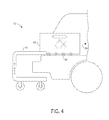
FIG. 4 is a side view of the shopping cart assembly having a basket in a cantilevered position; and
FIG. 5 shows the shopping cart assembly in a folded configuration and loaded into an automobile.
DETAILED DESCRIPTION OF THE DRAWINGS
Shopping carts come in a wide variety of shapes and sizes to serve the needs of many types of stores. Likewise, the present invention cart assembly can also be varied into many shapes and sizes. However, for the purposes of simplicity, a single exemplary embodiment of a shopping cart assembly is shown. The illustrated embodiment shows a shopping cart assembly configured for a grocery store and having a standard rectangular basket of about two feet wide by three feet long. The exemplary embodiment should be considered merely a representative form of a shopping cart. Accordingly, the specific dimensions and size proportions illustrated should not be considered limitations when interpreting the claims.
Referring to FIG. 1 in conjunction with FIG. 2, the exemplary embodiment of a cart assembly 10 is shown. The cart assembly 10 includes a basket 12. Although the basket 12 can have a fixed size, the basket 12 of the exemplary embodiment is adjustable in size. Accordingly, in the exemplary embodiment, the basket 12 is comprised of two or more overlapping sections. In the exemplary embodiment, two sections 13, 14 are shown for the sake of simplicity. Each section 13, 14 is comprised of a lattice base 15 and latticed walls 16 that extend upwardly from three sides of the base 15.
One basket section 13 is slightly smaller than the other basket section 14. The two basket sections 13, 14 overlap, with the smaller basket section 13 passing into the larger basket section 14. This configuration enables the configuration of the overall basket 12 to have a length L1 that can be selectively altered. In the shown embodiment, the basket 12 is adjustable in length, but otherwise rigid. In alternate embodiments, the latticed walls 16 of the basket 12 may be hinged so as to be collapsible when not in use. It should also be understood, that in alternate embodiments, the width W1 of the basket 12 can also be made to be adjustable.
A framework 20 is provided to support the basket 12. The framework 20 is supported by wheels 22. In this manner, the framework 20 and basket 12 can roll and operate in the same manner as a traditional shopping cart. The wheels 22 can be fixed wheels or caster wheels. Furthermore, the wheels can be different sizes. In the exemplary embodiment, wheels of uniform size are illustrated for the sake of simplicity.
The framework 20 has two side sections 24, 25 wherein the basket 12 is interposed between the two side sections 24, 25. Each of the two side sections 24, is preferably adjustable in height. Furthermore, the two side sections 24, 25 are interconnected by a plurality of telescoping supports 26. The telescoping configuration of the supports 26 enables the supports 26 to expand or contract when the basket 12 is enlarged or shortened. At least one locking mechanism 28 is provided on at least one of the telescoping supports 26. The locking mechanism 28 is used to lock the two side sections 24, 25 of the framework 20 at a fixed distance apart. This selectively sets the basket 12 at a fixed length L1.
The two side sections 24, 25 of the framework 20 are generally C-shaped, wherein each has a horizontal top rail 30, a horizontal bottom rail 32 and an adjustable vertical rail 34 that connects the two horizontal rails 30, 32 together.
The basket 12 is interconnected with the horizontal top rails 30 of the two side sections 24, 25 of the framework 20. However, the interconnection is not fixed. Rollers 36 are mounted to the basket 12. The rollers 36 engage tracks formed in or on the horizontal top rails 30. This enables the basket 12 to move relative the framework 20. The basket 12 can move between a fully retracted position and a cantilevered position, as will be further explained.
Referring to FIG. 3 and FIG. 4, the retracted position and the cantilevered position of the basket 12 are respectively shown. In FIG. 3, it can be seen that when the basket 12 is in its fully retracted position, most, if not all, of the rollers 36 are in direct contact with the horizontal top rails 30. Conversely, in FIG. 4, it can be seen that when the basket 12 is extended into its cantilevered position, the basket 12 extends away from the framework 20 as a cantilever and most of the rollers 36 do not contact the horizontal top rails 30. The rollers 36 on the basket 12 enable the basket 12 to move from a fully retracted position (FIG. 3) to a fully extended cantilevered position (FIG. 4) when the basket 12 is pulled forward in the direction of arrow 38.
When the basket 12 is in its extended cantilevered position, some of the rollers 36 on the sides of the basket 12 are exposed. The exposed rollers can roll onto the bed of a vehicle and help the basket roll into a vehicle. For large baskets 12, it should be understood that one or more rollers (not shown) may be placed under the middle sections of the basket 12 to help support the weight of the basket 12 inside a vehicle.
In FIG. 4, a vehicle with a flat bed is shown. Not all vehicles have flat beds. Rather, some have wells and other uneven structures. A cart assembly can be customized to a specific vehicle type. Collapsible supports can be made to automatically extend from the bottom of the basket to compensate for vehicle with uneven beds. Regardless to the vehicle type, what is important is that the basket 12 can be pushed on rollers into the bed of a vehicle without having to lift the weight of the basket 12.
Two pivot pins 40 (FIG. 2) are provided at opposite bottom corners of the basket 12. The pivot pins 40 engage the top rails 30 of the framework 20 only when the basket 12 is in its extended cantilevered position, such as is shown in FIG. 4.
Referring now to FIG. 5 in conjunction with FIG. 2, it will be understood that when the basket 12 is in its cantilevered position, the framework 20 can be rotated about the pivot pins 40. Once rotated, the wheels 22 that once faced downward are inverted so that they now face upward. The side sections 24, 25 of the framework 20 rotate into positions along the sides of the basket 12. The overall cart assembly 10 therefore becomes far more compact without affecting the size of the basket 12 or the contents of the basket 12.
Depending upon the size of the wheels 22 used, the wheels may be removable or foldable to further reduce space. Likewise the side sections 24, 25 of the framework 20 can be made further collapsible to further reduce size.
Referring to FIGS. 2 through 5 in unison, the operation of the cart assembly 10 will now be understood. A person shops in a store using the cart assembly 10 and its basket 12 in its fully retracted position. See FIG. 3. The basket 12 is filled with products to be purchased. After paying for the products, a person walks the cart assembly 10 to his/her vehicle. Preferably the vehicle is a hatchback, SUV, or similar vehicle that has a rear door.
Referring to FIG. 4, it can be seen that the cart assembly 10 is wheeled to the rear of the vehicle. The framework 20 has been previously adjusted in height to match the requirements of the vehicle. The basket 12 is then pulled forward to its cantilevered position. Once the basket 12 is in the cantilevered position, the entire cart assembly 10 is pushed toward the vehicle until the basket 12 enters the vehicle. Once in the vehicle, the rollers 36 on the bottom of the basket 12 rest upon the interior of the vehicle.
Referring to FIG. 5, it can be seen that once the interior of the vehicle supports the full weight of the basket 12, the framework 20 can be rotated up and around the basket 12. The basket 12 and the entire framework 20 are now supported by the basket rollers 36. The folded cart assembly 10 can then be pushed on the rollers 36 further into the interior of the vehicle. The rear door of the vehicle is then closed and the vehicle is ready to be driven.
Once at home, the loading process is reversed. The cart assembly 10 in its folded configuration (FIG. 5) is manipulated into its unfolded configuration (FIG. 4) by rotating the framework 20 back onto the ground. The basket 12 in its cantilever position (FIG. 4) is then moved to its retracted position (FIG. 3). The cart assembly 10 can then be rolled away from the vehicle without ever having to unload the basket 12.
It will be understood that the embodiment of the present invention cart that is illustrated is merely exemplary and that a person skilled in the art can make many variations to the design. For instance, the shape of the basket and shape of the frame can be varied in many ways. All such variations, modifications, and alternate embodiments are intended to be included within the scope of the present invention.

Claims (5)

1. A folding shopping cart assembly, comprising:
a basket having a bottom surface with rear corners;
pivot pins that extend from said basket proximate said rear corners;
a plurality of rollers attached to said basket proximate said bottom surface, wherein said basket rolls upon said plurality of rollers;
a framework for supporting said basket at an elevated height when said framework is in an upright position, said framework having two side sections that are interconnected by supports, wherein each side section has a top rail, a bottom rail and a vertical rail that connects said top rail to said bottom rail, and wherein each said top rail defines tracks for receiving said plurality of rollers attached to said basket, wherein said basket moves on said rollers relative said framework between a retracted position, where most of said plurality of rollers are in contact with said tracks and a cantilevered position where most of said rollers extend forward in front of said tracks and not in contact with said framework;
wherein when said basket is in said cantilevered position, said framework can rotate relative said basket out of said upright position into an inverted position; and
wheels coupled to said framework, wherein said wheels extend vertically downward for supporting said framework, when said framework is in said upright position and wherein said wheels extend vertically upward when said framework is in said inverted position.
2. The assembly according to claim 1, wherein each vertical rail of said framework is selectively adjustable in height.
3. The assembly according to claim 1, wherein supports of said basket is adjustable in length.
4. The assembly according to claim 3, wherein said supports of said framework are adjustable in length.
5. The assembly according to claim 1, wherein said basket is adjustable in length.
US12/326,870 2007-12-03 2008-12-02 Shopping cart assembly with folding legs Active 2029-12-28 US8083253B1 (en)

Priority Applications (1)

Application Number Priority Date Filing Date Title
US12/326,870 US8083253B1 (en) 2007-12-03 2008-12-02 Shopping cart assembly with folding legs

Applications Claiming Priority (2)

Application Number Priority Date Filing Date Title
US492407P 2007-12-03 2007-12-03
US12/326,870 US8083253B1 (en) 2007-12-03 2008-12-02 Shopping cart assembly with folding legs

Publications (1)

Publication Number Publication Date
US8083253B1 true US8083253B1 (en) 2011-12-27

Family

ID=45349773

Family Applications (1)

Application Number Title Priority Date Filing Date
US12/326,870 Active 2029-12-28 US8083253B1 (en) 2007-12-03 2008-12-02 Shopping cart assembly with folding legs

Country Status (1)

Country Link
US (1) US8083253B1 (en)

Cited By (17)

* Cited by examiner, † Cited by third party
Publication number Priority date Publication date Assignee Title
US20100314978A1 (en) * 2009-06-16 2010-12-16 Edwin Dizon Manalang Tool box storage assembly
US20100320732A1 (en) * 2008-03-05 2010-12-23 Gleid Elaine Dobrachinski Shopping Cart Designed For Vehicle Trunks
US20110304125A1 (en) * 2007-12-11 2011-12-15 Paul Fredy Ravnborg Collapsible shopping cart for transporting shopping from shop to car and from car to home
US20130049311A1 (en) * 2011-08-31 2013-02-28 Carl Metters Wheeled Personal Grocery Basket and Cart System
WO2013191700A1 (en) * 2012-06-21 2013-12-27 Beauchamp Brenda Jo Shopping cart with folding legs
US9102343B2 (en) 2013-10-07 2015-08-11 Hyundai Motor Company Electric cart apparatus
US9126610B1 (en) * 2014-05-16 2015-09-08 Sagi Abiri Collapsible shopping cart apparatus
EP3069956A1 (en) * 2015-03-18 2016-09-21 Clece, S.A. Table suitable for transferring baggage between two not necessarily coplanar surfaces
FR3038292A1 (en) * 2015-07-01 2017-01-06 Pierre Fernandez VEHICULABLE HANDLING TROLLEY WITH MOBILE TRAY
US9573610B1 (en) * 2015-04-03 2017-02-21 Trunkfit, Llc. Collapsible trunk-accessible carts
ITUB20160384A1 (en) * 2016-01-27 2017-07-27 Dorsi Paola Folding container with wheels for collecting and transporting goods for personal use
US10131373B1 (en) * 2017-11-20 2018-11-20 Ford Global Technologies, Llc Utility cart system for a motor vehicle
ES2738183A1 (en) * 2018-07-20 2020-01-20 Karim Cherif CART WITH FOLDABLE BASE STRUCTURE (Machine-translation by Google Translate, not legally binding)
US10850758B1 (en) * 2019-05-29 2020-12-01 Cara Patrice Griffith Telescoping cart apparatus and method
FR3103443A1 (en) * 2019-11-26 2021-05-28 Lsi Vehicle loading and unloading cart intended to transport tangible goods from the vehicle to a destination.
WO2021260709A1 (en) * 2020-06-27 2021-12-30 Gal Alexander Adjustable cart
WO2023126550A1 (en) * 2021-12-29 2023-07-06 Cartncar, S.L. Shopping cart

Citations (3)

* Cited by examiner, † Cited by third party
Publication number Priority date Publication date Assignee Title
US4492388A (en) 1980-12-29 1985-01-08 Wit Hendrik C De Collapsible shopping cart
US6536796B1 (en) * 2001-07-02 2003-03-25 Stephanie Solomon Collapsible wagon
US7080844B2 (en) * 2004-02-05 2006-07-25 Gilbert Bobby Espejo Transportable shopping cart

Patent Citations (3)

* Cited by examiner, † Cited by third party
Publication number Priority date Publication date Assignee Title
US4492388A (en) 1980-12-29 1985-01-08 Wit Hendrik C De Collapsible shopping cart
US6536796B1 (en) * 2001-07-02 2003-03-25 Stephanie Solomon Collapsible wagon
US7080844B2 (en) * 2004-02-05 2006-07-25 Gilbert Bobby Espejo Transportable shopping cart

Cited By (21)

* Cited by examiner, † Cited by third party
Publication number Priority date Publication date Assignee Title
US20110304125A1 (en) * 2007-12-11 2011-12-15 Paul Fredy Ravnborg Collapsible shopping cart for transporting shopping from shop to car and from car to home
US20100320732A1 (en) * 2008-03-05 2010-12-23 Gleid Elaine Dobrachinski Shopping Cart Designed For Vehicle Trunks
US20110115198A1 (en) * 2008-03-05 2011-05-19 Gleid Elaine Dobrachinski Shopping Cart Designed For Vehicle Trunks
US8540273B2 (en) * 2008-03-05 2013-09-24 Gleid Elaine Dobrachinski Shopping cart designed for vehicle trunks
US8157337B2 (en) * 2009-06-16 2012-04-17 Edwin Dizon Manalang Tool box storage assembly
US20100314978A1 (en) * 2009-06-16 2010-12-16 Edwin Dizon Manalang Tool box storage assembly
US9211899B2 (en) 2011-06-25 2015-12-15 Brenda Jo Beauchamp Shopping cart with folding legs
US20130049311A1 (en) * 2011-08-31 2013-02-28 Carl Metters Wheeled Personal Grocery Basket and Cart System
WO2013191700A1 (en) * 2012-06-21 2013-12-27 Beauchamp Brenda Jo Shopping cart with folding legs
US9102343B2 (en) 2013-10-07 2015-08-11 Hyundai Motor Company Electric cart apparatus
US9126610B1 (en) * 2014-05-16 2015-09-08 Sagi Abiri Collapsible shopping cart apparatus
EP3069956A1 (en) * 2015-03-18 2016-09-21 Clece, S.A. Table suitable for transferring baggage between two not necessarily coplanar surfaces
US9573610B1 (en) * 2015-04-03 2017-02-21 Trunkfit, Llc. Collapsible trunk-accessible carts
FR3038292A1 (en) * 2015-07-01 2017-01-06 Pierre Fernandez VEHICULABLE HANDLING TROLLEY WITH MOBILE TRAY
ITUB20160384A1 (en) * 2016-01-27 2017-07-27 Dorsi Paola Folding container with wheels for collecting and transporting goods for personal use
US10131373B1 (en) * 2017-11-20 2018-11-20 Ford Global Technologies, Llc Utility cart system for a motor vehicle
ES2738183A1 (en) * 2018-07-20 2020-01-20 Karim Cherif CART WITH FOLDABLE BASE STRUCTURE (Machine-translation by Google Translate, not legally binding)
US10850758B1 (en) * 2019-05-29 2020-12-01 Cara Patrice Griffith Telescoping cart apparatus and method
FR3103443A1 (en) * 2019-11-26 2021-05-28 Lsi Vehicle loading and unloading cart intended to transport tangible goods from the vehicle to a destination.
WO2021260709A1 (en) * 2020-06-27 2021-12-30 Gal Alexander Adjustable cart
WO2023126550A1 (en) * 2021-12-29 2023-07-06 Cartncar, S.L. Shopping cart

Similar Documents

Publication Publication Date Title
US8083253B1 (en) Shopping cart assembly with folding legs
US5503424A (en) Collapsible utility cart apparatus
US6860493B2 (en) Nestable cart
US6431319B1 (en) Height-adjustable equipment cart with detachable table
JP5799348B2 (en) Folding utility trailer
US9573610B1 (en) Collapsible trunk-accessible carts
JP5676490B2 (en) Modular shopping cart
US8408581B1 (en) Collapsible shopping cart device
US3827573A (en) Folding cart
US4953878A (en) Collapsible cart
US20180009461A1 (en) Utility Carts
JP2012519112A5 (en)
US6042128A (en) Collapsible shopping cart
US20040124598A1 (en) Grocery cart system
US3891228A (en) Carrier
KR20140120515A (en) Foldable shopping cart for vehicle
US3789957A (en) Check out system
US20180086358A1 (en) Retail store cart
EP1180463A1 (en) Shopping trolley
CN114206702A (en) Multi-stage delivery system and related apparatus
WO2007104071A1 (en) Folding shopping trolley
US20030094778A1 (en) Transport trolley, especially for the transporting of piece goods
US20090289017A1 (en) Transportable folding display rack
JP3172905B2 (en) cart
RU161747U1 (en) FOLDING TROLLEY

Legal Events

Date Code Title Description
STCF Information on status: patent grant

Free format text: PATENTED CASE

FEPP Fee payment procedure

Free format text: PATENT HOLDER CLAIMS MICRO ENTITY STATUS, ENTITY STATUS SET TO MICRO (ORIGINAL EVENT CODE: STOM); ENTITY STATUS OF PATENT OWNER: MICROENTITY

FPAY Fee payment

Year of fee payment: 4

FEPP Fee payment procedure

Free format text: MAINTENANCE FEE REMINDER MAILED (ORIGINAL EVENT CODE: REM.); ENTITY STATUS OF PATENT OWNER: MICROENTITY

FEPP Fee payment procedure

Free format text: SURCHARGE FOR LATE PAYMENT, MICRO ENTITY (ORIGINAL EVENT CODE: M3555); ENTITY STATUS OF PATENT OWNER: MICROENTITY

MAFP Maintenance fee payment

Free format text: PAYMENT OF MAINTENANCE FEE, 8TH YEAR, MICRO ENTITY (ORIGINAL EVENT CODE: M3552); ENTITY STATUS OF PATENT OWNER: MICROENTITY

Year of fee payment: 8

MAFP Maintenance fee payment

Free format text: PAYMENT OF MAINTENANCE FEE, 12TH YEAR, MICRO ENTITY (ORIGINAL EVENT CODE: M3553); ENTITY STATUS OF PATENT OWNER: MICROENTITY

Year of fee payment: 12