US8081730B2 - Monitoring device for connectors - Google Patents
Monitoring device for connectors Download PDFInfo
- Publication number
- US8081730B2 US8081730B2 US11/828,358 US82835807A US8081730B2 US 8081730 B2 US8081730 B2 US 8081730B2 US 82835807 A US82835807 A US 82835807A US 8081730 B2 US8081730 B2 US 8081730B2
- Authority
- US
- United States
- Prior art keywords
- time
- signal
- connector
- terminal
- processor
- Prior art date
- Legal status (The legal status is an assumption and is not a legal conclusion. Google has not performed a legal analysis and makes no representation as to the accuracy of the status listed.)
- Expired - Fee Related, expires
Links
Images

Classifications
-
- G—PHYSICS
- G07—CHECKING-DEVICES
- G07C—TIME OR ATTENDANCE REGISTERS; REGISTERING OR INDICATING THE WORKING OF MACHINES; GENERATING RANDOM NUMBERS; VOTING OR LOTTERY APPARATUS; ARRANGEMENTS, SYSTEMS OR APPARATUS FOR CHECKING NOT PROVIDED FOR ELSEWHERE
- G07C3/00—Registering or indicating the condition or the working of machines or other apparatus, other than vehicles
- G07C3/02—Registering or indicating working or idle time only
- G07C3/04—Registering or indicating working or idle time only using counting means or digital clocks
Definitions
- the present invention relates to monitoring devices, and particularly to a monitoring device for monitoring conditions of connectors.
- a connector may suffer wear and tear if used frequently.
- the wear and tear of the connector will influence the signals transmitted via the connector. Therefore, an operator should replace the connector when the service lifetime of the connector ends.
- An exemplary monitoring device includes: at least one time chip connected to a connector to generate a time signal and a count signal when the connector is working, the time signal indicating how long the connector is in use, the count signal indicating that the total number of times the connector has been used should be incremented by one; a processor connected to the at least one time chip to receive the time signal and count signal, and generate a data signal including a total service time and a total number of times the connector has been used; a clock generator connected to the processor to provide a clock signal; and an output port connected to the processor to output the data signal.
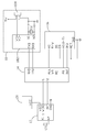
- the drawing is a circuit diagram of one embodiment of a monitoring device in accordance with the present invention.
- a monitoring device in accordance with an embodiment of the present invention includes a time chip 12 connected to a connector 20 to generate a time signal and a count signal when the connector 20 is in use, a processor 14 receiving the time signal and count signal, and generating a data signal including a total service time and a total of using times, a clock generator 16 connected to the processor 14 to provide a clock signal, and an output port 18 connected to the processor 14 to output the data signal to a peripheral device.
- the time signal indicates how long the connector is in use, and the count signal indicates that the total number of time the connector has been used should be incremented by one.
- the time chip 12 is a 1-wire time chip having a power terminal VDD, a data terminal 1-WIRE, an interrupt terminal INT, a ground pin GND, and two clock terminals X 1 and X 2 .
- the power terminal VDD of the time chip 12 is connected to a power terminal VCC of the connector 20 .
- the ground pin GND is grounded.
- a crystal resonator C 1 is connected between the clock terminals X 1 and X 2 of the time chip 12 to provide a clock signal to the time chip 12 .
- the data terminal 1-WIRE and the interrupt terminal INT are connected to the processor 14 to transmit the count signal and the time signal respectively.
- the processor 14 includes two data terminals P 1 ⁇ P 2 , a sending terminal TXD, a receiving terminal RXD, and five clock terminals ALE, WD, RD, P 0 , and INT.
- the data terminals P 1 ⁇ P 2 of the processor 14 are connected to the data terminal 1-WIRE and the interrupt terminal INT of the time chip 12 respectively to receive the count signal and the time signal.
- the sending terminal TXD and the receiving RXD terminal are connected to the output port 18 to send the data signal, and the clock terminals ALE, WD, RD, P 0 , and INT are connected to the clock generator 16 to receive a clock signal.
- the clock generator 16 includes a selection terminal CS, a mode terminal MOT, and a ground terminal GND all of which are grounded, and five clock terminals AS, R/W, DS, AD( 0 - 7 ), and IRQ respectively connected to the clock terminals ALE, WD, RD, P 0 , and INT of the processor 14 .
- the clock generator 16 provides a clock signal to the processor 14 .
- the output port 18 includes a USB interface chip 182 and a USB interface 184 .
- the USB interface chip 182 includes a sending terminal TXD connected to the receiving terminal RXD of the processor 14 , a receiving terminal RXD connected to the sending terminal TXD of the processor 14 , two clock terminals X 1 ⁇ X 2 connected to each other via a crystal resonator C 2 , and two data terminals VD+ and VD ⁇ connected to corresponding terminals of the USB interface 184 .
- the time chip 12 When the connector 20 is in use, the time chip 12 is turned on to generate the count signal via the data terminal 1-WIRE and the time signal via the interrupt terminal INT. That is, when the time chip 12 is turned on, the data terminal 1-WIRE transmits a count signal to make the processor 14 know the connector 20 is in use and add one to a count number, the processor 14 accumulates the signals to give a total of how many times the connector 20 has been used.
- the interrupt terminal INT of the time chip 12 transmits an interrupt signal in every cycle of the time chip 12 , and the processor 14 accumulates the interrupt signals to give a total of time in use of the connector 20 , which is equal to the number of the interrupt signals multiplied by a cycle time of the time chip 12 .
- the processor 14 transmits the total service time and using times to the output port 18 .
- the output port 18 is connected to the peripheral device such as a visual display to show the data to alert an operator if the connector 20 needs to be replaced.
- the number of the time chip 12 is not limited to one, it also can be two, or more that monitor a corresponding number of connectors.
Landscapes
- Physics & Mathematics (AREA)
- General Physics & Mathematics (AREA)
- Measurement Of Unknown Time Intervals (AREA)
Abstract
Description
Claims (5)
Applications Claiming Priority (3)
| Application Number | Priority Date | Filing Date | Title |
|---|---|---|---|
| CNA2007102007819A CN101320490A (en) | 2007-06-07 | 2007-06-07 | Connector usage status monitoring device |
| CN200710200781.9 | 2007-06-07 | ||
| CN200710200781 | 2007-06-07 |
Publications (2)
| Publication Number | Publication Date |
|---|---|
| US20080304613A1 US20080304613A1 (en) | 2008-12-11 |
| US8081730B2 true US8081730B2 (en) | 2011-12-20 |
Family
ID=40095876
Family Applications (1)
| Application Number | Title | Priority Date | Filing Date |
|---|---|---|---|
| US11/828,358 Expired - Fee Related US8081730B2 (en) | 2007-06-07 | 2007-07-26 | Monitoring device for connectors |
Country Status (2)
| Country | Link |
|---|---|
| US (1) | US8081730B2 (en) |
| CN (1) | CN101320490A (en) |
Families Citing this family (10)
| Publication number | Priority date | Publication date | Assignee | Title |
|---|---|---|---|---|
| JP4810564B2 (en) * | 2008-11-17 | 2011-11-09 | トヨタ自動車株式会社 | Charging cable for electric vehicle and management method thereof |
| CN103197225B (en) * | 2012-01-06 | 2017-03-29 | 珠海天威技术开发有限公司 | The method of testing of monobus chip |
| US8954628B2 (en) * | 2012-06-05 | 2015-02-10 | Htc Corporation | Portable device and peripheral extension dock |
| CN109077802B (en) * | 2018-09-11 | 2020-08-21 | 中聚科技股份有限公司 | Laser surgery optical fiber connector with using state storage and marking device |
| CN110147255B (en) * | 2019-05-17 | 2022-02-01 | 成都明为燃烧控制设备有限公司 | Low-power-consumption energy-saving method for calculating accumulated time of petroleum and natural gas equipment and tools |
| CN110716416B (en) * | 2019-10-30 | 2021-05-07 | 中国空空导弹研究院 | A connector type power-on timing device and power-on timing method |
| CN110826680A (en) * | 2019-11-08 | 2020-02-21 | 北京许继电气有限公司 | Network wiring operation counting equipment and method |
| CN112965356B (en) * | 2021-04-01 | 2022-05-17 | 中国空空导弹研究院 | A timing method for an aircraft power-on timing module |
| CN113960502A (en) * | 2021-09-15 | 2022-01-21 | 中国航空工业集团公司西安飞机设计研究所 | State detection method for universal EWIS electric connector |
| CN116650140A (en) * | 2023-05-12 | 2023-08-29 | 北京长木谷医疗科技股份有限公司 | An intelligent monitoring system for a surgical robot control device |
Citations (6)
| Publication number | Priority date | Publication date | Assignee | Title |
|---|---|---|---|---|
| US3878371A (en) * | 1973-02-07 | 1975-04-15 | Harry E Burke | Apparatus and method for compiling and recording operating data on equipment |
| US4180724A (en) * | 1978-03-31 | 1979-12-25 | E-Systems, Inc. | Solid state digital running time indicator |
| DE2922798A1 (en) | 1979-06-05 | 1980-12-11 | Reinhard Nikolai | Elapsed operating time counter for electrical appliance - comprises adaptor plug for connection of timer and appliance with counting initiated by load current flow |
| US4852104A (en) * | 1987-07-10 | 1989-07-25 | Curtis Instruments, Inc. | Solid-state reader device for a cumulative operations measurement system |
| JP2006079437A (en) | 2004-09-10 | 2006-03-23 | Fuji Xerox Co Ltd | Information processor and method of determining its connector life |
| US7864042B2 (en) * | 2007-08-21 | 2011-01-04 | Sze Ho Samuel Au | Daily life engagement time monitoring method and device |
-
2007
- 2007-06-07 CN CNA2007102007819A patent/CN101320490A/en active Pending
- 2007-07-26 US US11/828,358 patent/US8081730B2/en not_active Expired - Fee Related
Patent Citations (6)
| Publication number | Priority date | Publication date | Assignee | Title |
|---|---|---|---|---|
| US3878371A (en) * | 1973-02-07 | 1975-04-15 | Harry E Burke | Apparatus and method for compiling and recording operating data on equipment |
| US4180724A (en) * | 1978-03-31 | 1979-12-25 | E-Systems, Inc. | Solid state digital running time indicator |
| DE2922798A1 (en) | 1979-06-05 | 1980-12-11 | Reinhard Nikolai | Elapsed operating time counter for electrical appliance - comprises adaptor plug for connection of timer and appliance with counting initiated by load current flow |
| US4852104A (en) * | 1987-07-10 | 1989-07-25 | Curtis Instruments, Inc. | Solid-state reader device for a cumulative operations measurement system |
| JP2006079437A (en) | 2004-09-10 | 2006-03-23 | Fuji Xerox Co Ltd | Information processor and method of determining its connector life |
| US7864042B2 (en) * | 2007-08-21 | 2011-01-04 | Sze Ho Samuel Au | Daily life engagement time monitoring method and device |
Also Published As
| Publication number | Publication date |
|---|---|
| CN101320490A (en) | 2008-12-10 |
| US20080304613A1 (en) | 2008-12-11 |
Similar Documents
| Publication | Publication Date | Title |
|---|---|---|
| US8081730B2 (en) | Monitoring device for connectors | |
| US9305483B2 (en) | Display device including a timing controller with a self-recovery block and method for driving the same | |
| CN101315617A (en) | bus circuit device | |
| CN102789411A (en) | Mainboard diagnosis card and mainboard monitoring system | |
| US8433839B2 (en) | Connector assembly | |
| CN102479141A (en) | Processing system for monitoring power-on self-checking information | |
| CN203910233U (en) | LED display screen and monitoring system thereof | |
| US8239693B2 (en) | Built-in system power management circuit and motherboard with thereof | |
| US9020781B2 (en) | Monitoring memory module parameters in high performance computers | |
| TWI526819B (en) | Apparatus and method for computer debug | |
| CN101739320A (en) | Error detection device and method for server | |
| US9960886B2 (en) | Noise detection device | |
| JP2008228041A (en) | Signal transmitter and transmission module | |
| US8319655B2 (en) | Rewriting apparatus control circuit | |
| US6530048B1 (en) | I2C test single chip | |
| CN103823733B (en) | Disk state display device | |
| CN104112461A (en) | Hard disk detecting circuit | |
| JP3140544U (en) | Cordless interactive device | |
| CN110838274A (en) | Detection system and detection method for eDP interface display panel | |
| CN102200940A (en) | HDD (Hard Disk Driver) backboard testing system | |
| US20090295589A1 (en) | Connector apparatus | |
| TW201621661A (en) | Hard disk drive operating status detection system | |
| TWI691835B (en) | Detection control circuit and detection control method | |
| TWM483532U (en) | Motherboard and debug device | |
| US7337376B2 (en) | Method and system of self-test for a single infrared machine |
Legal Events
| Date | Code | Title | Description |
|---|---|---|---|
| AS | Assignment |
Owner name: HON HAI PRECISION INDUSTRY CO., LTD., TAIWAN Free format text: ASSIGNMENT OF ASSIGNORS INTEREST;ASSIGNORS:YUAN, GUANG-DONG;WANG, XIAN-MING;HUANG, CHUNG-CHI;AND OTHERS;REEL/FRAME:019610/0623 Effective date: 20070725 Owner name: HONG FU JIN PRECISION INDUSTRY (SHENZHEN) CO., LTD Free format text: ASSIGNMENT OF ASSIGNORS INTEREST;ASSIGNORS:YUAN, GUANG-DONG;WANG, XIAN-MING;HUANG, CHUNG-CHI;AND OTHERS;REEL/FRAME:019610/0623 Effective date: 20070725 |
|
| REMI | Maintenance fee reminder mailed | ||
| LAPS | Lapse for failure to pay maintenance fees | ||
| STCH | Information on status: patent discontinuation |
Free format text: PATENT EXPIRED DUE TO NONPAYMENT OF MAINTENANCE FEES UNDER 37 CFR 1.362 |
|
| STCH | Information on status: patent discontinuation |
Free format text: PATENT EXPIRED DUE TO NONPAYMENT OF MAINTENANCE FEES UNDER 37 CFR 1.362 |
|
| FP | Lapsed due to failure to pay maintenance fee |
Effective date: 20151220 |