US8080968B2 - Drive control device for a stepper motor and drive control method of the stepper motor - Google Patents
Drive control device for a stepper motor and drive control method of the stepper motor Download PDFInfo
- Publication number
- US8080968B2 US8080968B2 US12/318,101 US31810108A US8080968B2 US 8080968 B2 US8080968 B2 US 8080968B2 US 31810108 A US31810108 A US 31810108A US 8080968 B2 US8080968 B2 US 8080968B2
- Authority
- US
- United States
- Prior art keywords
- rotational angle
- target rotational
- stepper motor
- divisional
- control device
- Prior art date
- Legal status (The legal status is an assumption and is not a legal conclusion. Google has not performed a legal analysis and makes no representation as to the accuracy of the status listed.)
- Expired - Fee Related, expires
Links
- 238000000034 method Methods 0.000 title claims abstract description 85
- 238000005516 engineering process Methods 0.000 description 10
- 239000008186 active pharmaceutical agent Substances 0.000 description 8
- 230000004043 responsiveness Effects 0.000 description 3
- 238000012935 Averaging Methods 0.000 description 2
- 230000005540 biological transmission Effects 0.000 description 2
- 230000003247 decreasing effect Effects 0.000 description 2
- 238000012986 modification Methods 0.000 description 2
- 230000004048 modification Effects 0.000 description 2
- 238000013461 design Methods 0.000 description 1
- 238000010586 diagram Methods 0.000 description 1
- 230000000694 effects Effects 0.000 description 1
- 238000002474 experimental method Methods 0.000 description 1
Images


Classifications
-
- G—PHYSICS
- G01—MEASURING; TESTING
- G01R—MEASURING ELECTRIC VARIABLES; MEASURING MAGNETIC VARIABLES
- G01R7/00—Instruments capable of converting two or more currents or voltages into a single mechanical displacement
- G01R7/04—Instruments capable of converting two or more currents or voltages into a single mechanical displacement for forming a quotient
- G01R7/06—Instruments capable of converting two or more currents or voltages into a single mechanical displacement for forming a quotient moving-iron type
Definitions
- the present invention relates to a drive control technology of a stepper motor used to drive the indicator needle of an indicator needle type analog meter or the like, and relates especially to a technology that prevents loss of synchronism.
- an analog type meter apparatus that rotates an indicator needle by a stepper motor is widely known as a vehicle speed meter or the like.
- This meter apparatus includes a stepper motor control device.
- the stepper motor control device includes a sensor that detects physical quantities (vehicle speed) and a control device that calculates an indicating angle of the indicator needle based on inputs, that is, data corresponding to the physical quantities (vehicle speed) sent from a sensor and outputs the indicating angle.
- the control device implements a target rotational angle computation process that calculates a target rotational angle based on data corresponding to the physical quantities (vehicle speed) sent from the sensor, that is, a rotational angle of a drive shaft of the stepper motor necessary for obtaining the indicating angle, a target rotational angle change computation process that calculates a target rotational angle change which is a difference between a present rotational angle of the drive shaft of the stepper motor and the target rotational angle, and a divisional target rotational angle computation process that equally divides the target rotational angle change by a first divisional target rotational angle within a range not exceeding a rotational limit for loss of synchronism of the stepper motor.
- the control device is a drive control device of the stepper motor that drives the stepper motor by supplying to the stepper motor a second divisional target rotational angle which is a value calculated by the divisional target rotational angle computation process as a rotational angle per one control period.
- Loss of synchronism that is, misalignment generated between the actual indicating angle of the indicator needle and an indicating angle controlled by the drive control device for a stepper motor is problematic in a drive control device for a stepper motor as such.
- a drive control device for a stepper motor described in, for example, JP2004-328807A is known to prevent loss of synchronism in such cases of excessive rotational angle.
- This conventional drive control device for a stepper motor sets a limit value to a rotational angle of the drive shaft in a single control period and prevents an angle rotation surpassing the limit value during a single control period. Thereby loss of synchronism due to the above described excessive rotational angle changes of the drive shaft is prevented.
- FIG. 6 illustrates the cases in which 0°, 10°, 5° and 40° are respectively provided as the indicating angles of the indicator needle in control periods SS 1 , SS 2 , SS 3 and SS 4 .
- the indicator needle is rotated for 10°, that is, the limit value in control periods SS 4 , SS 5 and SS 6 .
- data is outputted to rotate the indicator needle for the difference, that is, the remaining 5° in the last control period SS 7 .
- the indicator needle in the case the indicator needle has to be rotated exceeding the limit value, the indicator needle is rotated first by the limit value, then by the remaining difference. Therefore, the rotational angle changes of the drive shaft are not constant and the rotation of the indicator needle is not smooth.
- the limit value is set, in consideration of responsiveness, to an upper limit of a value that does not generate loss of synchronism. In the case the necessary rotational angle changes are larger than the limit value, rotations are always repeated at the limit value so that in comparison to drives smaller than the limit value, the rotations are not preferable from the viewpoint to prevent loss of synchronism.
- An object of the present invention is to provide a drive control device for a stepper motor and a drive control method of the stepper motor that always rotates a drive shaft at a constant angle change, enables the smooth rotation of the drive shaft and reduces output chances to reach the limit value so that performances to prevent loss of synchronization can be improved.
- a stepper motor control device and a drive control method of a stepper motor includes a sensor that detects physical quantities (vehicle speed) and a control device that operates a stepper motor based on data corresponding to the physical quantities (vehicle speed) sent from the sensor.
- the control device implements a target rotational angle computation process that calculates a target rotational angle of a drive shaft of the stepper motor based on data corresponding to the physical quantities (vehicle speed) sent from the sensor, a target rotational angle change computation process that calculates a target rotational angle change which is a difference between a present rotational angle of the drive shaft of the stepper motor and the target rotational angle, and a divisional target rotational angle computation process that equally divides the target rotational angle change by a first divisional target rotational angle within a range not exceeding a rotational limit for loss of synchronism of the stepper motor.
- the control device is a drive control device of the stepper motor that drives the stepper motor by supplying to the stepper motor a second divisional target rotational angle which is a value calculated by the divisional target rotational angle computation process as a rotational angle per one control period.
- FIG. 1 is a constitutional explanatory diagram that illustrates a constitution of a drive control device for a stepper motor according to a first embodiment, that is, a best embodiment of the present invention.
- FIG. 2 is a flowchart that illustrates the process flows in a control unit and a motor drive control circuit of the drive control device for a stepper motor of the first embodiment.
- FIG. 3 is a flowchart that illustrates the details of a limitation process of stepper illustrated in FIG. 2 .
- FIG. 4 is a time chart that illustrates an operative example of the drive control device for a stepper motor of the first embodiment, especially, an example of the changes of a target indicating angle.
- FIG. 5 is a time chart that illustrates an operative example of the drive control device for a stepper motor of the first embodiment, especially, an example of the changes of an indicating command angle.
- FIG. 6 is a time chart that illustrates a comparison example with the first embodiment, especially, changes of the indicating command angle based on conventional technologies.
- FIG. 7 is a flow chart that illustrates the details of a limitation process in a drive control device for a stepper motor of the second embodiment.
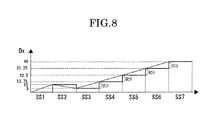
- FIG. 8 is a time chart that illustrates an operative example of the drive control device for a stepper motor of the second embodiment, especially, an example of the changes of an indicating command angle.
- a stepper motor control device of the present embodiment includes a sensor that detects physical quantities (vehicle speed) and a control device that operates a stepper motor based on data corresponding to the physical quantities (vehicle speed) sent from the sensor.
- the control device implements a target rotational angle computation process that calculates a target rotational angle of a drive shaft of the stepper motor based on data corresponding to the physical quantities (vehicle speed) sent from the sensor, a target rotational angle change computation process that calculates a target rotational angle change which is a difference between a present rotational angle of the drive shaft of the stepper motor and the target rotational angle and a divisional target rotational angle computation process that equally divides the target rotational angle change by a first divisional target rotational angle within a range not exceeding a rotational limit for loss of synchronism of the stepper motor.
- the control device is a drive control device of the stepper motor that drives the stepper motor by supplying to the stepper motor a second divisional target rotational angle which is a value calculated by the divisional target rotational angle computation process as a rotational angle per one control period.
- a drive control device for a stepper motor A according to a first embodiment of the present invention is described hereinbelow.
- the drive control device for a stepper motor A of the first embodiment includes a control unit (control device) 1 , a motor drive control circuit (control device) 2 and a stepper motor 3 .
- the stepper motor 3 is used for a vehicle speed display apparatus abbreviated hereby for illustration. That is to say, the vehicle speed display apparatus is a well-known analog type display apparatus that displays speed by setting an indicator needle 4 to rotate along a scale engraved on a dial (abbreviated for illustration) accompanying the rotation of a drive shaft 3 a driven by the stepper motor 3 .
- Vehicle speed data DS outputted from the vehicle speed sensor 5 is inputted to the control unit (control device) 1 by set periods (10 ms in embodiment 1). Based on the vehicle speed data DS, the control unit (control device) 1 implements a target rotational angle computation process (indicating angle computation process, target rotational angle computation step) that calculates a target rotational angle (target indicating angle) DA of the indicator needle 4 and an indicating angle signals output process that outputs to the motor drive control circuit (control device) 2 indicating angle signals S ⁇ illustrating the target rotational angle (target indicating angle) DA.
- a target rotational angle computation process indicating angle computation process, target rotational angle computation step
- the indicating angle signals S ⁇ are outputted with pre-set sending periods.
- the indicating angle signals S ⁇ are outputted with 10 ms periods.
- the indicating angle signals S ⁇ are inputted to the motor drive control circuit (control device) 2 .
- the motor drive control circuit (control device) 2 implements a target rotational angle change computation process that calculates a target rotational angle change RR, that is, the difference between the target rotational angle (target indicating angle) DA and a present rotational angle Dx of the drive shaft 3 a (an indicating command angle Dx of the last time due to data transmission delay).
- the motor drive control circuit (control device) 2 also implements a divisional target rotational angle computation process that equally divides the target rotational angle change (RR) by a first divisional target rotational angle (R ⁇ ) within a range not exceeding a rotational limit for loss of synchronism of the stepper motor (in the range, rotational angle changes within each one control period (SS) are values below a limitation value SA and only minimum control periods are necessary) and calculates a second divisional target rotational angle, that is, a rotational angle per one control period.
- Drive signals MS that rotate the drive shaft 3 a are outputted based on the second divisional target rotational angle.
- the first divisional target rotational angle (R ⁇ ) is an amount of divisional target rotational angle which is equally divided within a range that does not exceed a rotational limit (limitation value SA) for loss of synchronism of the stepper motor.
- FIG. 2 illustrates the process flows in the control unit (control device) 1 and the motor drive control circuit (control device) 2 described above.
- process illustrated in the flow chart of FIG. 2 is repeatedly implemented with 10 ms as the control period SS.
- step S 1 the vehicle speed data DS is read-in. Furthermore, in the next step S 2 , data is subjected to an averaging process. Thereafter, in step S 3 , a compensation process is performed.
- the above-described averaging process and compensation process are general data processes that do not constitute the executive summary of the present invention, and thus the detailed descriptions of these processes are abbreviated.
- the vehicle speed data DS is converted to the target rotational angle (target indicating angle) DA of the indicator needle 4 . That is, a process (the target rotational angle computation process) is implemented to convert the speed to be indicated by the indicator needle 4 to a rotational angle from the initial position where the speed indicated by the indicator needle 4 is 0 km/h.
- step S 5 a limitation process is implemented.
- the limitation process is a process that limits the rotational angle changes in a single control period SS to a value within a pre-set limitation value SA.
- the limitation value SA does not exceed the upper limit value of angle changes with no risk of loss of synchronism when the indicator needle 4 , that is, the drive shaft 3 a is rotated towards the target indicating angle DA.
- the limitation value SA 10° is used as the limitation value SA.
- the limitation value SA can use any appropriate value based on experiment or the like.
- the limitation value SA is the first divisional target rotational angle (R ⁇ ).
- the target rotational angle (target indicating angle) DA is applied to a filter process. Thereafter, the drive signals MS that rotate the drive shaft 3 a to the target rotational angle (target indicating angle) DA are outputted.
- the drive signals MS are outputted for every pre-set drive unit period in pre-set control periods SS.
- 1 ms is used as the drive unit period so that in the control period SS of 10 ms, drive signals MS are outputted 10 times.
- step S 5 the details of the limitation process of step S 5 are described using the flowchart of FIG. 3 .
- the limitation process first implements the divisional target rotational angle computation process in step S 21 .
- the divisional target rotational angle computation process is a process that calculates a “quotient” and a “remainder” in the case the target rotational angle change RR, which is the rotational angle necessary for the indicator needle 4 to indicate the target indicating angle DA, is divided by the first divisional target rotational angle (R ⁇ ).
- a divisional target rotational angle computation process is implemented to equally divide the target rotational angle change RR by the first divisional target rotational angle within a range not exceeding a rotational limit (the limitation value SA) for loss of synchronism of the stepper motor. The “quotient” and the “remainder” thereof are calculated.
- step S 22 whether there is a “remainder” to the computation results of step S 21 or not is determined. In the case the “remainder” exists, the process then proceeds to step S 23 .
- step S 23 a process that sets a new “quotient” value yielded by adding “1” to the “quotient” of the computation results of step S 21 is performed to obtain a second divisional target rotational angle differing from the first divisional target rotational angle.
- the stepper motor is then driven based on the second divisional target rotational angle.
- the second divisional target rotational angle is a maximum value within a range in which the stepper motor does not lose synchronism.
- step S 25 a process that equally divides the indicating command angle Dx of the drive shaft 3 a in the control period SS of this time is performed by the following formula (1).
- Dx D x-1 ⁇ ( D x-1 ⁇ DA )/quotient (1)
- equal division is performed by allocating and adjusting uniformly the “remainder” to each control period SS. Put in another way, allocated quantities to the first divisional target rotational angle are uniform.
- the vehicle speed data DS is inputted to the control unit 1 by set periods (10 ms).
- the control unit 1 then reads-in the vehicle speed data DS (step S 1 ). Based on the vehicle speed data DS, the target rotational angle (target indicating angle) DA of the indicator needle 4 is calculated (steps S 2 ⁇ S 3 ⁇ S 4 ). Furthermore, the limitation process is implemented based on the target rotational angle (target indicating angle) DA so that the indicating command angle Dx with a value below the limitation value SA is calculated (step S 5 ).
- the motor drive control circuit 2 outputs in correspondence to the indicating command angle Dx drive signals that can rotate the drive shaft 3 a for one tenth of the divisional target rotational angle amount R ⁇ by a single output, that is, drive signals MS that can reach the indicating command angle Dx by 10 outputs.
- FIG. 4 illustrates an example in which the target indicating angle DA calculated from vehicle speed data DS shifts in the sequence of 0° ⁇ 10° ⁇ 5° ⁇ 40° in each of control periods SS 1 through SS 7 .
- the indicating command angle Dx DA.
- the indicating command angle Dx 0°.
- the indicating command angle Dx 10°.
- the indicating command angle Dx 5°.
- drive signals MS that shift the indicating angle of the indicator needle 4 from 0° to 10° are outputted. That is, drive signals MS that rotate the drive shaft 3 a +1° each time are outputted 10 times.
- + is a rotation in the clock-wise direction
- ⁇ is a rotation in the counter clock-wise direction.
- drive signals that shift back the indicating angle of the indicator needle 4 from 10° to 5° are outputted. That is, drives signals that rotate the drive shaft 3 a ⁇ 0.5° each time are outputted 10 times.
- the indicating angle of the indicator needle 4 needs to be shifted from 5° to 13.75° so that drive signals setting the second divisional target rotational angle (rotational angle per control period) to +8.75° (smaller than the limitation value SA) are outputted. That is, drive signals MS that rotate the drive shaft 3 a +8.75°/10 each time are outputted 10 times.
- the indicating angle of the indicator needle 4 needs to be shifted from 13.75° to 22.5° so that drive signals setting the second divisional target rotational angle to +8.75° (smaller than the limitation value SA) are outputted. That is, drive signals MS that rotate the drive shaft 3 a +8.75°/10 each time are outputted 10 times.
- drive signals setting the second divisional target rotational angle (rotational angle of the drive shaft 3 a per control period) to +8.75° (smaller than the limitation value SA) are outputted.
- the indicator needle 4 rotates by the second divisional target rotational angle at a constant angle change towards the target rotational angle (target indicating angle) 40°.
- the second divisional target rotational angle is an angle change smaller than the limitation value SA.
- the indicator needle 4 in the case the rotational angle (target rotational angle change RR) necessary to rotate the indicator needle 4 towards the target rotational angle (target indicating angle) DA exceeds the limitation value SA, the indicator needle 4 , that is, the drive shaft 3 a can possibly rotate towards the target rotational angle (target indicating angle) DA at a constant angle change due to the first divisional target rotational angle R ⁇ that has been equally divided within a range that does not exceed the rotational limit (limitation value SA) for loss of synchronism of the stepper motor. Therefore, it is possible for the indicator needle 4 to rotate smoothly.
- the second divisional target rotational angle (rotational angle of the drive shaft 3 a per control period SS) is a value smaller than the limitation value SA so that the drive shaft 3 a rotates at the limitation value SA only when “remainder” is not generated. Therefore, in comparison to conventional technologies that always rotate at the limitation value SA, output chances that reach the limitation value SA are reduced and performance to prevent loss of synchronism can be improved.
- the same number of control periods SS are necessary to reach the target rotational angle (target indicating angle) DA so that the same control responsiveness as conventional technologies can be secured.
- the second embodiment is a modified example of the first embodiment, so that only the differences involved are described. Descriptions of the same constitutions, operations and effects as the first embodiment are abbreviated.
- process contents of the limitation process implemented in step S 5 differ from the first embodiment.
- FIG. 7 illustrates the process flows of the limitation process of the second embodiment.
- the process proceeds to step S 32 .
- the process proceeds to step S 36 where a process that sets the indicating command angle Dx to equal the target indicating angle DA is implemented.
- step S 32 the divisional target rotational angle computation process that calculates the “quotient” and the “remainder” using the following formula (2) is implemented.
- W is a set value for divisional use and is a value smaller than the limitation value SA illustrated in the first embodiment.
- W is the first divisional target rotational angle (R ⁇ ).
- step S 33 whether the indicating command angle D x-1 of the last time (the present rotational angle) is larger than the target rotational angle (target indicating angle) DA or not is determined so that whether rotation is directed to an increased side of the rotational angle or to a decreased side of the rotational angle can be determined.
- the process proceeds to step S 34 and the indicating command angle Dx is calculated by the following formula (3).
- the process proceeds to step S 35 and the indicating command angle Dx is calculated by the following formula (4).
- Dx D x-1 ⁇ W ⁇ “remainder”/“quotient” (3)
- Dx D x-1 +W +“remainder”/“quotient” (4)
- the example illustrated in FIG. 8 also describes in the same way to the first embodiment the case in which the target rotational angle (target indicating angle) DA shifts in the sequence of 0° ⁇ 10° ⁇ 5° ⁇ 40°.
- the process proceeds in the sequence of step S 31 ⁇ S 36 .
- step S 33 the indicating angle is on the increased side so that based on the process of step S 35 , calculations of the indicating command angle Dx are performed using the above formula (4).
- step S 32 that is, calculations of
- the indicator needle 4 in the case the target rotational angle change RR till the target rotational angle (target indicating angle) DA is reached exceeds the limitation value SA, the indicator needle 4 , that is, the drive shaft 3 a can possibly rotate at a constant angle change due to the divisional target rotational angle computation process.
- the divisional target rotational angle computation process equally divides the target rotational angle change RR by the first divisional target rotational angle R ⁇ .
- the first divisional target rotational angle R ⁇ is within a range that does not exceed the rotational limit (limitation value SA) for loss of synchronism of the stepper motor. Therefore, it is possible for the indicator needle 4 to rotate smoothly.
- divisional calculations are implemented using a set value, W, for divisional use and smaller than the limitation value SA.
- W for divisional use
- the “remainder” is divided by the “quotient” to obtain a value.
- the value is then added to the set value W for divisional use. Therefore, chances that drive the indicator needle 4 , that is, the drive shaft 3 a by the rotational angle change at the limitation value SA can be reduced and performances to prevent loss of synchronism can be improved.
- a stepper motor that rotates an indicator needle of a vehicle speed display apparatus is adapted with a drive control device of a stepper motor.
- the drive control device of a stepper motor can be used for a display apparatus other than the speed display apparatus and apparatuses other than the display apparatus if the apparatuses drive the stepper motor in correspondence to signals inputted from a sensor.
- 10 ms is illustrated as the control period SS and 1 ms is illustrated as the unit drive period but these time can be randomly set based on the properties of the control device.
- a limitation value SA of 10° is illustrated as the value of a range that does not exceed the rotation limit for loss of synchronism.
- this limitation value is not limited to 10° as long as the rotational angle changes do not generate loss of synchronism (within a range that does not exceed the rotation limit for loss of synchronism).
- “8” is illustrated as the set value W for divisional use. But it is not limited to such and other values can be used as long as the values can set the divisional target rotational angle amount RO to below the limitation value.
- a drive control device of a stepper motor in the case the drive shaft is rotated from the present rotational angle to the target rotational angle, calculates target rotational angle change (target rotational angle change computation process), that is, the difference between both angles.
- the drive control device of the stepper motor then implements a divisional target rotational angle computation process that equally divides the target rotational angle change by a first divisional target rotational angle within a range not exceeding a rotational limit (limitation value SA) for loss of synchronism of the stepper motor.
- the drive control device of the stepper motor drives the stepper motor by supplying to the stepper motor a second divisional target rotational angle which is a value calculated by the divisional target rotational angle computation process as a rotational angle per one control period.
- the drive shaft rotates by the divisional target rotational angle from the present rotational angle towards the target rotational angle at a constant rotational angle change so that rotation is conducted smoothly.
- the divisional target rotational angle as the rotational angle per control period is a value not exceeding the rotation limit for loss of synchronism so that in comparison to a drive control device for a stepper motor that always rotates at the rotation limit for loss of synchronism, rotation frequencies at the rotation limit for loss of synchronism drastically decrease and performance to prevent loss of synchronism is improved.
Landscapes
- Physics & Mathematics (AREA)
- General Physics & Mathematics (AREA)
- Control Of Stepping Motors (AREA)
Abstract
Description
Dx=D x-1−(D x-1 −DA)/quotient (1)
|D x-1 −DA|/W (2)
Hereby, W is a set value for divisional use and is a value smaller than the limitation value SA illustrated in the first embodiment. In the second embodiment, W has approximately 80% of an upper limit value that does not generate loss of synchronism, specifically, W=8°. In the second embodiment, W is the first divisional target rotational angle (Rθ).
Dx=D x-1 −W−“remainder”/“quotient” (3)
Dx=D x-1 +W+“remainder”/“quotient” (4)
Claims (3)
Applications Claiming Priority (2)
| Application Number | Priority Date | Filing Date | Title |
|---|---|---|---|
| JP2007-337278 | 2007-12-27 | ||
| JP2007337278 | 2007-12-27 |
Publications (2)
| Publication Number | Publication Date |
|---|---|
| US20090167232A1 US20090167232A1 (en) | 2009-07-02 |
| US8080968B2 true US8080968B2 (en) | 2011-12-20 |
Family
ID=40419182
Family Applications (1)
| Application Number | Title | Priority Date | Filing Date |
|---|---|---|---|
| US12/318,101 Expired - Fee Related US8080968B2 (en) | 2007-12-27 | 2008-12-22 | Drive control device for a stepper motor and drive control method of the stepper motor |
Country Status (4)
| Country | Link |
|---|---|
| US (1) | US8080968B2 (en) |
| EP (1) | EP2075589B1 (en) |
| JP (1) | JP4423339B2 (en) |
| CN (1) | CN101471620B (en) |
Cited By (1)
| Publication number | Priority date | Publication date | Assignee | Title |
|---|---|---|---|---|
| US20150204700A1 (en) * | 2014-01-21 | 2015-07-23 | Johnson Controls Automotive Electronics Sas | Indicator device, notably for motor vehicles |
Families Citing this family (5)
| Publication number | Priority date | Publication date | Assignee | Title |
|---|---|---|---|---|
| CN102843084B (en) * | 2012-09-11 | 2015-02-18 | 济南优耐特汽车电子有限公司 | Acceleration and deceleration driving method for stepping motor |
| CN103701372B (en) * | 2012-09-27 | 2017-07-04 | 比亚迪股份有限公司 | A kind of step failing out detecting method of synchronous motor |
| CN104682797A (en) * | 2014-12-15 | 2015-06-03 | 上海德尔福汽车空调系统有限公司 | Control method for unipolar stepping motor for automobile air conditioner |
| CN106712589B (en) * | 2015-07-23 | 2019-03-29 | 北京宝沃汽车有限公司 | A kind of method and apparatus for matching motor synchronously control period and drive cycle |
| CN113452294A (en) * | 2021-06-29 | 2021-09-28 | 北京长安汽车工程技术研究有限责任公司 | Speed indication control method and system of mechanical speedometer and automobile |
Citations (4)
| Publication number | Priority date | Publication date | Assignee | Title |
|---|---|---|---|---|
| JP2004328807A (en) | 2003-04-21 | 2004-11-18 | Calsonic Kansei Corp | Stepping motor control unit |
| US20050083008A1 (en) * | 2003-10-06 | 2005-04-21 | Yazaki Corporation | Pointing position correcting method, pointing position correcting apparatus, and pointing apparatus |
| US6956351B2 (en) * | 2003-06-25 | 2005-10-18 | Yazaki Corporation | Driving device for stepping motor |
| JP2007228763A (en) * | 2006-02-24 | 2007-09-06 | Denso Corp | Instrument device |
Family Cites Families (4)
| Publication number | Priority date | Publication date | Assignee | Title |
|---|---|---|---|---|
| DE19521445A1 (en) * | 1995-06-16 | 1996-12-19 | Moto Meter Gmbh | Method for controlling a stepper motor and device therefor |
| JP3013775B2 (en) * | 1996-04-11 | 2000-02-28 | 日本精機株式会社 | Driving device for stepping motor type instrument |
| JP2953502B2 (en) * | 1996-06-28 | 1999-09-27 | 日本精機株式会社 | Driving device for stepping motor type instrument |
| JP3728262B2 (en) * | 2002-03-27 | 2005-12-21 | キヤノン株式会社 | Step motor control circuit and step motor control method |
-
2008
- 2008-11-12 JP JP2008289978A patent/JP4423339B2/en not_active Expired - Fee Related
- 2008-12-11 CN CN2008101866129A patent/CN101471620B/en not_active Expired - Fee Related
- 2008-12-22 US US12/318,101 patent/US8080968B2/en not_active Expired - Fee Related
- 2008-12-23 EP EP08172771.1A patent/EP2075589B1/en not_active Ceased
Patent Citations (5)
| Publication number | Priority date | Publication date | Assignee | Title |
|---|---|---|---|---|
| JP2004328807A (en) | 2003-04-21 | 2004-11-18 | Calsonic Kansei Corp | Stepping motor control unit |
| US6956351B2 (en) * | 2003-06-25 | 2005-10-18 | Yazaki Corporation | Driving device for stepping motor |
| US20050083008A1 (en) * | 2003-10-06 | 2005-04-21 | Yazaki Corporation | Pointing position correcting method, pointing position correcting apparatus, and pointing apparatus |
| US7034496B2 (en) * | 2003-10-06 | 2006-04-25 | Yazaki Corporation | Pointing position correcting method, pointing position correcting apparatus, and pointing apparatus |
| JP2007228763A (en) * | 2006-02-24 | 2007-09-06 | Denso Corp | Instrument device |
Non-Patent Citations (1)
| Title |
|---|
| Machine translation of JP2007228763A. * |
Cited By (2)
| Publication number | Priority date | Publication date | Assignee | Title |
|---|---|---|---|---|
| US20150204700A1 (en) * | 2014-01-21 | 2015-07-23 | Johnson Controls Automotive Electronics Sas | Indicator device, notably for motor vehicles |
| US9689721B2 (en) * | 2014-01-21 | 2017-06-27 | Johnson Controls Automotive Electronics Sas | Indicator device, notably for motor vehicles |
Also Published As
| Publication number | Publication date |
|---|---|
| US20090167232A1 (en) | 2009-07-02 |
| CN101471620A (en) | 2009-07-01 |
| JP4423339B2 (en) | 2010-03-03 |
| EP2075589A3 (en) | 2014-01-01 |
| JP2009178022A (en) | 2009-08-06 |
| EP2075589B1 (en) | 2015-10-07 |
| CN101471620B (en) | 2011-04-06 |
| EP2075589A2 (en) | 2009-07-01 |
Similar Documents
| Publication | Publication Date | Title |
|---|---|---|
| US8080968B2 (en) | Drive control device for a stepper motor and drive control method of the stepper motor | |
| CN108512472A (en) | A kind of follow-up control method and its system based on electronic gear | |
| US10041821B2 (en) | Indicating-needle type meter device | |
| US6215270B1 (en) | Synchronous control device | |
| US7447579B2 (en) | Method for measuring absolute steering angle of steering shaft of vehicle | |
| JP7221272B2 (en) | Method and device for estimating torque pulsation of electric motor | |
| EP0588403B1 (en) | Method and apparatus for driving a gauge | |
| CN108195387B (en) | AR-HUD Navigation System and Its GPS Data Verification and Correction Method | |
| CN111917347A (en) | Method for eliminating influence of gear clearance error and related product | |
| WO2026000846A1 (en) | Synchronization point adjustment method, apparatus and device, and storage medium and computer program product | |
| JP4497105B2 (en) | Instrument device | |
| EP4441882B1 (en) | High-precision rotor position determination for use in position and/or torque control at low speed | |
| CN113646618B (en) | Method and control device for controlling rotational speed | |
| US7005826B2 (en) | Method for enhancing the control response of a drive train having backlash and/or elasticity of a machine tool or production machine | |
| JP6623878B2 (en) | Vehicle information acquisition device and vehicle information acquisition method | |
| WO2001094891A1 (en) | Meter driving method | |
| CN105099324B (en) | The state observer and its velocity estimation and system of driver | |
| JP2009128232A (en) | Meter apparatus | |
| CN121633833B (en) | Test system of rotary equipment | |
| KR100974595B1 (en) | Vehicle speed signal generator | |
| JP2007010333A (en) | Meter device | |
| JPH08261798A (en) | Needle type display device | |
| CN116232153A (en) | A Method of Compensating Motor Position by Look-up Table | |
| US6510399B1 (en) | Method of driving a meter | |
| JP3407546B2 (en) | Analog instruments |
Legal Events
| Date | Code | Title | Description |
|---|---|---|---|
| AS | Assignment |
Owner name: CALSONIC KANSEI CORPORATION, JAPAN Free format text: ASSIGNMENT OF ASSIGNORS INTEREST;ASSIGNOR:KATAGIRI, DAI;REEL/FRAME:022079/0993 Effective date: 20081110 |
|
| STCF | Information on status: patent grant |
Free format text: PATENTED CASE |
|
| FEPP | Fee payment procedure |
Free format text: PAYOR NUMBER ASSIGNED (ORIGINAL EVENT CODE: ASPN); ENTITY STATUS OF PATENT OWNER: LARGE ENTITY |
|
| FPAY | Fee payment |
Year of fee payment: 4 |
|
| FEPP | Fee payment procedure |
Free format text: MAINTENANCE FEE REMINDER MAILED (ORIGINAL EVENT CODE: REM.); ENTITY STATUS OF PATENT OWNER: LARGE ENTITY |
|
| LAPS | Lapse for failure to pay maintenance fees |
Free format text: PATENT EXPIRED FOR FAILURE TO PAY MAINTENANCE FEES (ORIGINAL EVENT CODE: EXP.); ENTITY STATUS OF PATENT OWNER: LARGE ENTITY |
|
| STCH | Information on status: patent discontinuation |
Free format text: PATENT EXPIRED DUE TO NONPAYMENT OF MAINTENANCE FEES UNDER 37 CFR 1.362 |
|
| FP | Lapsed due to failure to pay maintenance fee |
Effective date: 20191220 |