US8079476B2 - Corner post structure for packaging - Google Patents
Corner post structure for packaging Download PDFInfo
- Publication number
- US8079476B2 US8079476B2 US12/384,677 US38467709A US8079476B2 US 8079476 B2 US8079476 B2 US 8079476B2 US 38467709 A US38467709 A US 38467709A US 8079476 B2 US8079476 B2 US 8079476B2
- Authority
- US
- United States
- Prior art keywords
- leg
- corner post
- wave pattern
- post structure
- layers
- Prior art date
- Legal status (The legal status is an assumption and is not a legal conclusion. Google has not performed a legal analysis and makes no representation as to the accuracy of the status listed.)
- Active
Links
- 238000004806 packaging method and process Methods 0.000 title claims description 5
- 239000000463 material Substances 0.000 claims abstract description 47
- 238000010276 construction Methods 0.000 claims abstract description 4
- 230000006835 compression Effects 0.000 claims description 17
- 238000007906 compression Methods 0.000 claims description 17
- 239000000853 adhesive Substances 0.000 claims description 6
- 230000001070 adhesive effect Effects 0.000 claims description 6
- 238000000034 method Methods 0.000 claims description 6
- 239000011800 void material Substances 0.000 claims description 6
- 238000007493 shaping process Methods 0.000 claims 1
- 238000004519 manufacturing process Methods 0.000 abstract description 4
- 239000000123 paper Substances 0.000 description 18
- 239000011087 paperboard Substances 0.000 description 10
- 230000008901 benefit Effects 0.000 description 3
- 238000012986 modification Methods 0.000 description 3
- 230000004048 modification Effects 0.000 description 3
- 230000001012 protector Effects 0.000 description 3
- 230000008859 change Effects 0.000 description 2
- 230000008569 process Effects 0.000 description 2
- 230000001681 protective effect Effects 0.000 description 2
- 238000005299 abrasion Methods 0.000 description 1
- 230000003466 anti-cipated effect Effects 0.000 description 1
- 239000011324 bead Substances 0.000 description 1
- 238000000576 coating method Methods 0.000 description 1
- 238000005520 cutting process Methods 0.000 description 1
- 230000002349 favourable effect Effects 0.000 description 1
- 239000000835 fiber Substances 0.000 description 1
- 238000003475 lamination Methods 0.000 description 1
- 230000009467 reduction Effects 0.000 description 1
- 238000004804 winding Methods 0.000 description 1
Images


Classifications
-
- B—PERFORMING OPERATIONS; TRANSPORTING
- B65—CONVEYING; PACKING; STORING; HANDLING THIN OR FILAMENTARY MATERIAL
- B65D—CONTAINERS FOR STORAGE OR TRANSPORT OF ARTICLES OR MATERIALS, e.g. BAGS, BARRELS, BOTTLES, BOXES, CANS, CARTONS, CRATES, DRUMS, JARS, TANKS, HOPPERS, FORWARDING CONTAINERS; ACCESSORIES, CLOSURES, OR FITTINGS THEREFOR; PACKAGING ELEMENTS; PACKAGES
- B65D81/00—Containers, packaging elements, or packages, for contents presenting particular transport or storage problems, or adapted to be used for non-packaging purposes after removal of contents
- B65D81/02—Containers, packaging elements, or packages, for contents presenting particular transport or storage problems, or adapted to be used for non-packaging purposes after removal of contents specially adapted to protect contents from mechanical damage
- B65D81/05—Containers, packaging elements, or packages, for contents presenting particular transport or storage problems, or adapted to be used for non-packaging purposes after removal of contents specially adapted to protect contents from mechanical damage maintaining contents at spaced relation from package walls, or from other contents
- B65D81/053—Corner, edge or end protectors
- B65D81/054—Protectors contacting two generally perpendicular surfaces of the packaged article, e.g. edge protectors
Definitions
- This patent relates to a corner post not of the typical tubular type to be used to cushion and protect packaged articles, such as furniture or large appliances. More particularly, this patent relates to an improved non-tubular type corner post configured into a wave pattern.
- Conventional tubular type corner posts are made by cutting the paper to a desired length, then applying adhesive to the paper, and winding the coated paper around a mandrel to form one or more cylindrical tubes having a substantially circular cross-section, sliding the wound paper tubes onto a forming tool while the tubes are still malleable, forming the tubes into a desired shape, and allowing the adhesive between the paper layers to set up and form the finished product.
- Gardner U.S. Pat. No. 4,483,444 discloses a corner post having a cross-sectional profile that accommodates overhang of the post relative to a bottom board without substantially reducing the resistance of the post to compressive forces.
- This tubular type corner post has a cross-sectional profile that is constant along the height of the post.
- Hughes U.S. Pat. No. 5,267,651 discloses a corner post having laterally directed stiffening beads extending at an acute angle into free engagement with the opposite wall. When subjected to sufficient lateral force, the beads collapse onto themselves forming intermediate layers between the inner and outer walls.
- This invention relates to packaging, and more particularly to an article of manufacture for corner post construction.
- a non-tubular apparatus By having multiple, independent layers of material formed together into a wave pattern, a non-tubular apparatus has been created. This apparatus does not have inner and outer walls contained.
- the independent layers can be comprised of semicircles, triangles, flat spots, squares or any other geometrical shape contrived to place more material along the longitudinal axis.
- This invention has only two surfaces exposed from the materials being laminated together, which are the inside and outside surfaces.
- This design is not of the wound paperboard tube type, nor is it simply laminated plies of paperboard formed into angled corner protectors.
- This invention is a combination of these types. It uses some of the benefits of each and creates a much stronger product in compression strength while still providing cushion protection.
- Laminated paperboard corner protectors or V-board have lacked adequate stacking strength and cushion protection, as they are rigid and thin. This wave pattern creates a cushioning affect when side impact occurs, allowing forces to be gently and evenly distributed. As shown in FIG. 1 b , with less surface area in direct contact with the product contained, this wave design reduces the area of product at risk to side impact damage.
- the wound paperboard tube industry uses corner protectors that contain inner and outer walls with a few sections of support (beads) for compression strength.
- this wave design structure requires less paper to achieve greater compression strength than most of these products that are found on the market.
- the corner post is made by applying adhesive to the paper. Then while the layers of paper are still malleable, it is to be formed into the shape of FIG. 1 which can be comprised of semicircles, triangles, flat spots, squares or any other geometrical shape, and allowing the adhesive between the paper layers to set up and form the finished wave pattern corner post.
- corner posts are placed at each corner of an article between the product and the inside corners of the package.
- the corner posts protect the article against vertical (axial) and horizontal (lateral) forces.
- a product typically a large appliance
- a protective sleeve typically made of paperboard or corrugated board, is placed over the appliance to form the four sidewalls of the container.
- the corner posts are placed at each corner around the appliance and between the product and protective sleeve.
- a paperboard or corrugated top is placed over the package. Straps may be placed around the container to better secure the corner posts between the appliance and the container. The packaged appliances may then be stacked on top of each other for warehousing.
- FIG. 3 Another possibility is shown in FIG. 3 as a lateral type compression post with a first standoff foot 10 and a second standoff foot 12 used to elevate the post.
- corner posts are commonly made with sides set at right angles as seen in FIG. 1 .
- this design can be formed with extraordinarily long leg lengths and/or varying leg lengths which are adjusted to meet particular performance needs, but not limited to right angles.
- the present invention is an improved corner post construction for supporting and cushioning contained products.
- the corner post has multiple layers of material formed together into a wave pattern, which can be comprised of any geometrical shape contrived to place more material along the longitudinal axis without creating a tubular type apparatus which contains an inner and outer wall, but merely having two surfaces exposed from the lamination of the materials being used.
- the corner post is made from material comprising a means, which includes varying layer sheet widths, and/or varying amounts of layers contained within said corner post, which can be made of a lesser grade material to reduce costs and adjust compression strengths to accommodate different application specifications.
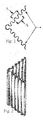
- FIG. 1 is a top plan view of the invention showing the open inside corner FIG. 1 a and the formed wave design.
- the detail A-A in FIG. 1 shows the direction of lateral forces and how the cushioning affect is provided.
- FIG. 2 is a perspective view of the invention standing on end and showing the full length.
- FIG. 3 is a top plan view of a Stand-off Compression Post as described.
- FIG. 4 is a perspective view of a Stand-off Compression Post standing on end and showing the full length.
- This new corner post design described as being used for the packaging industry, can be made from multiple or independent layers of material formed together into a wave pattern consisting of any geometrical shape imaginable to place more material along the longitudinal axis without creating a tubular type apparatus which has a hollow area contained within inner and outer walls.
- leg lengths can be adjusted to accommodate different design requirements and is used to further regulate the compression strength characteristics desired.
- the use of different paper grade materials can further increase the flexibility in design changes without having to splice the different paper grades into their respective positions.
- These layers of material can be laminated together as a web type operation from roll stock or laid up as sheets and even folded from a single source during the forming process.
- a cushioning affect is created when lateral forces are applied to the product package, which evenly distributes the forces along the sides and a void area is provided as shown in FIG. 1 a , at the inside corner for further protection of the very corner of the product corner itself.
- This minimum area in direct contact with the product contained further reduces the area exposed to damage from lateral forces and also reduces the surface area in which abrasion coatings might be required.
- more or less material may be placed along the longitudinal axis for an increase in compression strength or a reduction in the amount of materials being used to achieve a desired, compression strength to paper weight ratio.
Landscapes
- Engineering & Computer Science (AREA)
- Mechanical Engineering (AREA)
- Buffer Packaging (AREA)
Abstract
Description
Claims (17)
Priority Applications (1)
| Application Number | Priority Date | Filing Date | Title |
|---|---|---|---|
| US12/384,677 US8079476B2 (en) | 2009-01-26 | 2009-04-08 | Corner post structure for packaging |
Applications Claiming Priority (2)
| Application Number | Priority Date | Filing Date | Title |
|---|---|---|---|
| US20590309P | 2009-01-26 | 2009-01-26 | |
| US12/384,677 US8079476B2 (en) | 2009-01-26 | 2009-04-08 | Corner post structure for packaging |
Publications (2)
| Publication Number | Publication Date |
|---|---|
| US20100187153A1 US20100187153A1 (en) | 2010-07-29 |
| US8079476B2 true US8079476B2 (en) | 2011-12-20 |
Family
ID=42353305
Family Applications (1)
| Application Number | Title | Priority Date | Filing Date |
|---|---|---|---|
| US12/384,677 Active US8079476B2 (en) | 2009-01-26 | 2009-04-08 | Corner post structure for packaging |
Country Status (1)
| Country | Link |
|---|---|
| US (1) | US8079476B2 (en) |
Cited By (17)
| Publication number | Priority date | Publication date | Assignee | Title |
|---|---|---|---|---|
| US20130062344A1 (en) * | 2011-09-08 | 2013-03-14 | Samsung Electronics Co., Ltd. | Packaging box and method for fabricating the same |
| US9511920B2 (en) | 2013-07-09 | 2016-12-06 | T & M Design, Llc | Edge protector |
| US20180086532A1 (en) * | 2016-09-26 | 2018-03-29 | Corruven Canada Inc. | Corner protector |
| US10081949B2 (en) | 2015-06-26 | 2018-09-25 | Jad Honein | Interchangeable bracket flange system |
| US10822138B1 (en) * | 2018-04-27 | 2020-11-03 | Rational Packaging Llc | Packaging assembly with corrugated corner elements |
| US10899524B1 (en) * | 2017-02-06 | 2021-01-26 | Rational Packaging Llc | Self-locating structural packaging element |
| US11104501B1 (en) * | 2018-04-27 | 2021-08-31 | Rational Packaging Llc | Void filling structural packaging element |
| US11208253B1 (en) | 2020-07-07 | 2021-12-28 | Rational Packaging Llc | Packaging assembly with support insert |
| US11358776B1 (en) * | 2017-02-06 | 2022-06-14 | Rational Packaging Llc | Brace element and corner post assembly |
| US11492171B1 (en) * | 2017-02-06 | 2022-11-08 | Rational Packaging Llc | Scored corrugated corner elements |
| US11505393B1 (en) * | 2020-07-07 | 2022-11-22 | Rational Packaging Llc | Packaging assembly with multi-slit support insert |
| US11577902B1 (en) * | 2017-02-06 | 2023-02-14 | Rational Packaging Llc | Structural packaging element with locating stem |
| US11643265B1 (en) * | 2017-02-06 | 2023-05-09 | Rational Packaging Llc | Corrugated offset corner elements |
| US12037179B2 (en) | 2022-10-12 | 2024-07-16 | Sonoco Development, Inc. | Notched corner post for appliance packaging |
| USD1106078S1 (en) | 2024-07-10 | 2025-12-16 | Steven L. Morey | Foldable wave fold back corner |
| USD1106819S1 (en) | 2024-07-10 | 2025-12-23 | Steven L. Morey | Foldable corrugated corner element |
| USD1111194S1 (en) | 2024-01-02 | 2026-02-03 | Rational Packaging Llc | Foldable corner post |
Families Citing this family (15)
| Publication number | Priority date | Publication date | Assignee | Title |
|---|---|---|---|---|
| EP2490276B1 (en) * | 2009-10-13 | 2016-12-07 | LG Chem, Ltd. | Battery module with superior structural stability |
| US10518499B2 (en) * | 2016-09-26 | 2019-12-31 | Corruven Canada Inc. | Foldable composite material sheet and structure |
| USD871213S1 (en) * | 2017-02-06 | 2019-12-31 | Rational Packaging Llc | Corner packing element |
| USD1010445S1 (en) * | 2018-04-27 | 2024-01-09 | Rational Packaging Llc | Combined scalloped brace and wave post |
| US11597578B1 (en) * | 2017-02-06 | 2023-03-07 | Rational Packaging Llc | Hourglass shaped packaging element |
| US12116183B1 (en) * | 2017-02-06 | 2024-10-15 | Rational Packaging Llc | Multi-scored corrugated corner element |
| USD1011190S1 (en) * | 2018-04-27 | 2024-01-16 | Rational Packaging Llc | Scalloped wave post |
| US11613418B1 (en) * | 2017-02-06 | 2023-03-28 | Rational Packaging Llc | Trilobular packaging element |
| US11591153B1 (en) * | 2017-02-06 | 2023-02-28 | Rational Packaging Llc | Bifurcated trilobular packaging element |
| US11655093B1 (en) * | 2017-02-06 | 2023-05-23 | Rational Packaging Llc | Integrally formed trilobular packaging element |
| US11603248B1 (en) * | 2017-02-06 | 2023-03-14 | Rational Packaging Llc | Foldable corrugated corner elements |
| USD871908S1 (en) * | 2017-02-06 | 2020-01-07 | Rational Packaging Llc | Corrugated packing element |
| CN111439482A (en) * | 2019-01-16 | 2020-07-24 | 海信视像科技股份有限公司 | Cushion and packaging structure |
| WO2021012678A1 (en) * | 2019-07-24 | 2021-01-28 | 南京联众工程技术有限公司 | Corner connection structure for pipeline or container having box-shaped steel corrugated plate structure |
| CN112478445B (en) * | 2019-10-11 | 2022-10-18 | 苏州喜全软件科技有限公司 | Desktop computer display screen, keyboard and mouse assembly and transportation device |
Citations (11)
| Publication number | Priority date | Publication date | Assignee | Title |
|---|---|---|---|---|
| USRE19121E (en) * | 1934-03-27 | Shield fob filing bricks | ||
| US3049260A (en) * | 1960-07-13 | 1962-08-14 | Alton H Stone | Cushioning material |
| US3433354A (en) * | 1968-01-29 | 1969-03-18 | Paper Extrusions Co | Resilient angle member |
| US4202449A (en) * | 1977-02-24 | 1980-05-13 | Anders Bendt | Protecting device for edges |
| US4244471A (en) * | 1979-04-09 | 1981-01-13 | Whirlpool Corporation | Packaging system |
| US5799797A (en) * | 1996-12-26 | 1998-09-01 | Stone Container Corporation | Corner post construction |
| US5899046A (en) * | 1997-09-17 | 1999-05-04 | Hughes; Barry T. | Edge protector for masonry products and a system for its application |
| US6186329B1 (en) * | 1999-08-27 | 2001-02-13 | Sonoco Development, Inc. | Multiple-grade paper corner post |
| US6527119B1 (en) * | 2001-09-05 | 2003-03-04 | Illinois Tool Works Inc. | Angleboard edge protector |
| US6629608B2 (en) * | 2001-08-22 | 2003-10-07 | Western Pulp Products Co. | Shipping protector |
| US7383952B2 (en) * | 2005-04-27 | 2008-06-10 | Illinois Tool Works Inc. | Corner or edge protector exhibiting improved flexural strength and resistance properties |
-
2009
- 2009-04-08 US US12/384,677 patent/US8079476B2/en active Active
Patent Citations (11)
| Publication number | Priority date | Publication date | Assignee | Title |
|---|---|---|---|---|
| USRE19121E (en) * | 1934-03-27 | Shield fob filing bricks | ||
| US3049260A (en) * | 1960-07-13 | 1962-08-14 | Alton H Stone | Cushioning material |
| US3433354A (en) * | 1968-01-29 | 1969-03-18 | Paper Extrusions Co | Resilient angle member |
| US4202449A (en) * | 1977-02-24 | 1980-05-13 | Anders Bendt | Protecting device for edges |
| US4244471A (en) * | 1979-04-09 | 1981-01-13 | Whirlpool Corporation | Packaging system |
| US5799797A (en) * | 1996-12-26 | 1998-09-01 | Stone Container Corporation | Corner post construction |
| US5899046A (en) * | 1997-09-17 | 1999-05-04 | Hughes; Barry T. | Edge protector for masonry products and a system for its application |
| US6186329B1 (en) * | 1999-08-27 | 2001-02-13 | Sonoco Development, Inc. | Multiple-grade paper corner post |
| US6629608B2 (en) * | 2001-08-22 | 2003-10-07 | Western Pulp Products Co. | Shipping protector |
| US6527119B1 (en) * | 2001-09-05 | 2003-03-04 | Illinois Tool Works Inc. | Angleboard edge protector |
| US7383952B2 (en) * | 2005-04-27 | 2008-06-10 | Illinois Tool Works Inc. | Corner or edge protector exhibiting improved flexural strength and resistance properties |
Cited By (18)
| Publication number | Priority date | Publication date | Assignee | Title |
|---|---|---|---|---|
| US20130062344A1 (en) * | 2011-09-08 | 2013-03-14 | Samsung Electronics Co., Ltd. | Packaging box and method for fabricating the same |
| US9511920B2 (en) | 2013-07-09 | 2016-12-06 | T & M Design, Llc | Edge protector |
| US10081949B2 (en) | 2015-06-26 | 2018-09-25 | Jad Honein | Interchangeable bracket flange system |
| US20180086532A1 (en) * | 2016-09-26 | 2018-03-29 | Corruven Canada Inc. | Corner protector |
| US10513383B2 (en) * | 2016-09-26 | 2019-12-24 | Corruven Canada Inc. | Corner protector |
| US11577902B1 (en) * | 2017-02-06 | 2023-02-14 | Rational Packaging Llc | Structural packaging element with locating stem |
| US10899524B1 (en) * | 2017-02-06 | 2021-01-26 | Rational Packaging Llc | Self-locating structural packaging element |
| US11358776B1 (en) * | 2017-02-06 | 2022-06-14 | Rational Packaging Llc | Brace element and corner post assembly |
| US11492171B1 (en) * | 2017-02-06 | 2022-11-08 | Rational Packaging Llc | Scored corrugated corner elements |
| US11643265B1 (en) * | 2017-02-06 | 2023-05-09 | Rational Packaging Llc | Corrugated offset corner elements |
| US11104501B1 (en) * | 2018-04-27 | 2021-08-31 | Rational Packaging Llc | Void filling structural packaging element |
| US10822138B1 (en) * | 2018-04-27 | 2020-11-03 | Rational Packaging Llc | Packaging assembly with corrugated corner elements |
| US11208253B1 (en) | 2020-07-07 | 2021-12-28 | Rational Packaging Llc | Packaging assembly with support insert |
| US11505393B1 (en) * | 2020-07-07 | 2022-11-22 | Rational Packaging Llc | Packaging assembly with multi-slit support insert |
| US12037179B2 (en) | 2022-10-12 | 2024-07-16 | Sonoco Development, Inc. | Notched corner post for appliance packaging |
| USD1111194S1 (en) | 2024-01-02 | 2026-02-03 | Rational Packaging Llc | Foldable corner post |
| USD1106078S1 (en) | 2024-07-10 | 2025-12-16 | Steven L. Morey | Foldable wave fold back corner |
| USD1106819S1 (en) | 2024-07-10 | 2025-12-23 | Steven L. Morey | Foldable corrugated corner element |
Also Published As
| Publication number | Publication date |
|---|---|
| US20100187153A1 (en) | 2010-07-29 |
Similar Documents
| Publication | Publication Date | Title |
|---|---|---|
| US8079476B2 (en) | Corner post structure for packaging | |
| US6186329B1 (en) | Multiple-grade paper corner post | |
| CA2535586C (en) | I-beam wall corner post | |
| CA2446757C (en) | Single-piece fold-to-shape protective device | |
| US7625616B2 (en) | Support post with improved axial strength | |
| US6513662B1 (en) | Variable profile corner post | |
| US9649823B2 (en) | Flexible cellulosic fiber-based honeycomb material | |
| US6540080B2 (en) | Protective wrap for protecting and packaging and method for producing same | |
| WO2005019091B1 (en) | I-beam wall corner post | |
| US6190756B1 (en) | Hollow connected body and packaging material | |
| JP2005178909A (en) | Linearly drawable support comprising a plurality of overlapped sections | |
| US7661579B2 (en) | Packaging container, and method and apparatus for making same | |
| WO2015075580A1 (en) | Structural elements made from corrugated sheets | |
| WO2011059347A1 (en) | Corrugated board with cushioning strips protective packaging | |
| US20040112947A1 (en) | Packaging insert for product separation and protection | |
| US20120247603A1 (en) | Method of manufacturing paper tube corner posts | |
| EP1539596B1 (en) | Corrugated paperboard shipping pallet and support member | |
| US20250074685A1 (en) | Packaging filler | |
| KR19990074095A (en) | Cardboard for packaging and manufacturing method thereof | |
| MXPA06001709A (en) | I-beam wall corner post | |
| AU2015200725A1 (en) | Improvements in and relating to packaging and machines therefor | |
| JP2025517596A (en) | Paperboard protective corner and its manufacturing method | |
| NZ704926A (en) | Improvements in and relating to packaging and machines therefor | |
| TH37827B (en) | Display stand |
Legal Events
| Date | Code | Title | Description |
|---|---|---|---|
| STCF | Information on status: patent grant |
Free format text: PATENTED CASE |
|
| FPAY | Fee payment |
Year of fee payment: 4 |
|
| AS | Assignment |
Owner name: CRAM, JOEL WAYNE, TENNESSEE Free format text: ASSIGNMENT OF ASSIGNORS INTEREST;ASSIGNOR:SIMMS, WALTER BRIAN;REEL/FRAME:036506/0551 Effective date: 20150806 |
|
| AS | Assignment |
Owner name: RATIONAL PACKAGING, LLC, TENNESSEE Free format text: ASSIGNMENT OF ASSIGNORS INTEREST;ASSIGNOR:CRAM, JOEL WAYNE;REEL/FRAME:036930/0185 Effective date: 20151022 |
|
| MAFP | Maintenance fee payment |
Free format text: PAYMENT OF MAINTENANCE FEE, 8TH YR, SMALL ENTITY (ORIGINAL EVENT CODE: M2552); ENTITY STATUS OF PATENT OWNER: SMALL ENTITY Year of fee payment: 8 |
|
| FEPP | Fee payment procedure |
Free format text: MAINTENANCE FEE REMINDER MAILED (ORIGINAL EVENT CODE: REM.); ENTITY STATUS OF PATENT OWNER: SMALL ENTITY |
|
| FEPP | Fee payment procedure |
Free format text: 11.5 YR SURCHARGE- LATE PMT W/IN 6 MO, SMALL ENTITY (ORIGINAL EVENT CODE: M2556); ENTITY STATUS OF PATENT OWNER: SMALL ENTITY |
|
| MAFP | Maintenance fee payment |
Free format text: PAYMENT OF MAINTENANCE FEE, 12TH YR, SMALL ENTITY (ORIGINAL EVENT CODE: M2553); ENTITY STATUS OF PATENT OWNER: SMALL ENTITY Year of fee payment: 12 |
|
| AS | Assignment |
Owner name: COMPASS GROUP DIVERSIFIED HOLDINGS LLC, CONNECTICUT Free format text: SECURITY INTEREST;ASSIGNOR:RATIONAL PACKAGING, LLC;REEL/FRAME:069095/0607 Effective date: 20241001 |