US8079474B1 - Stackable container and method for making the same - Google Patents
Stackable container and method for making the same Download PDFInfo
- Publication number
- US8079474B1 US8079474B1 US12/183,016 US18301608A US8079474B1 US 8079474 B1 US8079474 B1 US 8079474B1 US 18301608 A US18301608 A US 18301608A US 8079474 B1 US8079474 B1 US 8079474B1
- Authority
- US
- United States
- Prior art keywords
- fold
- flaps
- sidewall
- flap
- stackable container
- Prior art date
- Legal status (The legal status is an assumption and is not a legal conclusion. Google has not performed a legal analysis and makes no representation as to the accuracy of the status listed.)
- Active, expires
Links
- 238000000034 method Methods 0.000 title claims description 19
- 238000004519 manufacturing process Methods 0.000 claims description 5
- 238000013459 approach Methods 0.000 abstract description 5
- 239000000123 paper Substances 0.000 description 7
- 238000010586 diagram Methods 0.000 description 6
- 239000000463 material Substances 0.000 description 5
- 239000002985 plastic film Substances 0.000 description 4
- 239000000853 adhesive Substances 0.000 description 3
- 230000001070 adhesive effect Effects 0.000 description 3
- 239000003292 glue Substances 0.000 description 3
- 238000012986 modification Methods 0.000 description 3
- 230000004048 modification Effects 0.000 description 3
- 230000008901 benefit Effects 0.000 description 2
- 239000011111 cardboard Substances 0.000 description 2
- 238000009833 condensation Methods 0.000 description 2
- 230000005494 condensation Effects 0.000 description 2
- 238000007373 indentation Methods 0.000 description 2
- 238000004806 packaging method and process Methods 0.000 description 2
- 239000011087 paperboard Substances 0.000 description 2
- 239000004033 plastic Substances 0.000 description 2
- 238000001556 precipitation Methods 0.000 description 2
- 238000004078 waterproofing Methods 0.000 description 2
- 230000015556 catabolic process Effects 0.000 description 1
- 230000000295 complement effect Effects 0.000 description 1
- 238000006731 degradation reaction Methods 0.000 description 1
- 235000021022 fresh fruits Nutrition 0.000 description 1
- 239000000126 substance Substances 0.000 description 1
- 235000013311 vegetables Nutrition 0.000 description 1
Images


Classifications
-
- B—PERFORMING OPERATIONS; TRANSPORTING
- B65—CONVEYING; PACKING; STORING; HANDLING THIN OR FILAMENTARY MATERIAL
- B65D—CONTAINERS FOR STORAGE OR TRANSPORT OF ARTICLES OR MATERIALS, e.g. BAGS, BARRELS, BOTTLES, BOXES, CANS, CARTONS, CRATES, DRUMS, JARS, TANKS, HOPPERS, FORWARDING CONTAINERS; ACCESSORIES, CLOSURES, OR FITTINGS THEREFOR; PACKAGING ELEMENTS; PACKAGES
- B65D5/00—Rigid or semi-rigid containers of polygonal cross-section, e.g. boxes, cartons or trays, formed by folding or erecting one or more blanks made of paper
- B65D5/001—Rigid or semi-rigid containers of polygonal cross-section, e.g. boxes, cartons or trays, formed by folding or erecting one or more blanks made of paper stackable
- B65D5/0015—Rigid or semi-rigid containers of polygonal cross-section, e.g. boxes, cartons or trays, formed by folding or erecting one or more blanks made of paper stackable the container being formed by folding up portions connected to a central panel
-
- B—PERFORMING OPERATIONS; TRANSPORTING
- B65—CONVEYING; PACKING; STORING; HANDLING THIN OR FILAMENTARY MATERIAL
- B65D—CONTAINERS FOR STORAGE OR TRANSPORT OF ARTICLES OR MATERIALS, e.g. BAGS, BARRELS, BOTTLES, BOXES, CANS, CARTONS, CRATES, DRUMS, JARS, TANKS, HOPPERS, FORWARDING CONTAINERS; ACCESSORIES, CLOSURES, OR FITTINGS THEREFOR; PACKAGING ELEMENTS; PACKAGES
- B65D5/00—Rigid or semi-rigid containers of polygonal cross-section, e.g. boxes, cartons or trays, formed by folding or erecting one or more blanks made of paper
- B65D5/42—Details of containers or of foldable or erectable container blanks
- B65D5/44—Integral, inserted or attached portions forming internal or external fittings
- B65D5/441—Reinforcements
- B65D5/443—Integral reinforcements, e.g. folds, flaps
-
- Y—GENERAL TAGGING OF NEW TECHNOLOGICAL DEVELOPMENTS; GENERAL TAGGING OF CROSS-SECTIONAL TECHNOLOGIES SPANNING OVER SEVERAL SECTIONS OF THE IPC; TECHNICAL SUBJECTS COVERED BY FORMER USPC CROSS-REFERENCE ART COLLECTIONS [XRACs] AND DIGESTS
- Y10—TECHNICAL SUBJECTS COVERED BY FORMER USPC
- Y10S—TECHNICAL SUBJECTS COVERED BY FORMER USPC CROSS-REFERENCE ART COLLECTIONS [XRACs] AND DIGESTS
- Y10S229/00—Envelopes, wrappers, and paperboard boxes
- Y10S229/915—Stacking feature
- Y10S229/919—Reinforced wall
Definitions
- the present invention generally relates to the field of containers. More specifically, embodiments of the present invention pertain to methods and structures for forming a stackable container.
- a stackable container is formed from a container blank.
- the weight-bearing walls of a container may conventionally include two wall flaps, one folded over the other.
- FIGS. 1 and 2 a container blank 100 and an erected stackable container 110 are shown.
- Load bearing wall 111 of container 110 may be formed by folding wall flap 101 of blank 100 over wall flap 102 at bridge regions 103 , thus forming projections 113 .
- projections 113 are covered by the outer surface of the container blank.
- the rectangular base 106 and/or the side wall 102 may have holes cut in them to receive the upwardly directed projections 115 from a lower container in the stack.
- the holes and projections allow a stack of containers to be indexed such that they stack vertically.
- Conventional packaging containers are typically formed from blanks made of corrugated board.
- Such corrugated board generally contains two outer layers of paperboard or cardboard (which generally has a relatively heavy weight), with an inner layer of corrugation (e.g., corrugated paper), but it may contain further layers (e.g., of an external paper or plastic sheet for further support, waterproofing and/or marking, e.g., with advertising and/or identification information; a further inner layer or sheet [e.g., of paper or plastic] between two layers of corrugation; etc.) or contain different materials (e.g., plastic sheet having a relatively high stiffness or modulus of elasticity).
- packaging containers are formed such that the “flutes,” or channels formed by the corrugation, are directed upward in the load bearing walls.
- the areas 112 between the projections comprise uncovered flutes.
- moisture may collect in these flutes due to outdoor precipitation, condensation in cold storage, and/or other natural and/or unnatural events. This moisture in the flutes may weaken the container over time.
- Embodiments of the present invention relate to stackable container blanks, stackable container structures, and methods for forming stackable container structures (e.g., by folding blanks).
- the invention relates to a stackable container blank having (a) a base having a first pair of opposed base edges (typically, but not necessarily, shorter base edges) and a second pair of opposed base edges (typically, but not necessarily, longer base edges), (b) two first sidewall structures, each first sidewall structure foldably attached to one of the first base edges, and (c) two second sidewall structures, each second sidewall structure foldably attached to one of the second base edges.
- Each of the second sidewall structures (e.g., structures on the longer sides) has (i) a wall flap foldably attached to one of the second base edges along a first fold line, (ii) an index fold-down flap foldably attached to the wall flap along a second fold line, and (iii) a plurality of inner fold-down flaps foldably attached to the wall flap along a third fold line, wherein the index flap and inner fold-down flaps alternate.
- the first two opposing sides or the second two opposing sides may be longer, or the first two opposing sides and the second two opposing sides may be substantially equal in length (thus forming a square), but preferably the second two opposing sides are longer.
- the wall flap includes one or more holes configured to provide slots for indexing with another stackable container.
- the wall flap and the index fold-down flap form index projections configured to fit into the slots.
- each second sidewall structure has two index flaps (thus forming two index projections on each of the two sides) and three inner fold-down flaps, where inner fold down flaps and index flaps alternate along the wall flap.
- each second sidewall structure has one index fold-down flap and two inner fold-down flaps, where the index fold-down flap is between the two inner fold-down flaps.
- the wall flap and/or one or more of the inner fold-down flaps have one or more holes configured to provide an opening for air flow.
- the width at the top of the holes may be greater than the width of the bottom of the holes (e.g., the holes may have a generally triangular shape with an apex nearest the fold line between the index flap and the fold-down flap).
- the fold lines between the wall flap and the index and inner wall flaps are generally parallel to the fold line between the second sidewall structure and the base (e.g., the first fold line).
- the distance between the first fold line and the second fold line is greater than the distance between the first fold line and the third fold line.
- the index fold-down flaps are folded over the wall flap, they form a projection above the fold line of the inner fold-down flaps.
- the width of the inner fold-down flap is substantially equal to a width of the wall flap (e.g., excluding the height of the projection formed by the index fold-down flap).
- an edge of the index fold-down flap and an edge of one of the inner fold-down flaps are separated by a cut-line in the blank.
- each index fold-down flap may be separated from its neighboring inner fold-down flaps by such a cut-line.
- each of the second sidewall structures includes first extension flaps foldably attached to each of the inner fold-down flaps closest to the first sidewall structures (e.g., attached to the inner fold-down flaps at the end of the wall flaps), along first extension fold lines approximately parallel to the first base edges.
- the second sidewall structures also include second extension flaps foldably attached to the wall flap at ends closest to the first sidewall structures, along second extension fold lines approximately parallel to the first base edges.
- the first and second extension flaps generally extend beyond lines formed by the first opposing sides of the base edges.
- the invention also relates to a stackable container that includes (a) a base having a first pair of opposed base edges and a second pair of opposed base edges, (b) two first sidewall structures, each first sidewall structure foldably attached to the first base edges at an angle of from about 90 degrees to about 100 degrees, and (c) two second sidewall structures.
- the second sidewall structures generally include (i) a wall flap foldably attached to one of the second two opposing edges of the base along a first fold line at an angle of from about 90 degrees to about 100 degrees, (ii) an index fold-down flap foldably attached to the wall flap along a second fold line at an angle of about 180 degrees, and (iii) a plurality of inner fold-down flaps foldably attached to the wall flap along a third fold line at an angle of about 180 degrees.
- each wall flap and/or the base of the stackable container may include one or more holes configured to provide slots for indexing with another stackable container.
- each wall flap and the index fold-down flap form index projections configured to fit into the slots.
- each second sidewall structure has two index flaps (thus forming two index projections on each of the two sides) and three inner fold-down flaps, where inner fold-down flaps and index fold-down flaps alternate along the wall flap.
- the wall flap and/or one or more of the inner fold-down flaps have one or more holes configured to provide an opening for air flow.
- holes in the inner fold-down flaps are generally aligned with complimentary holes in the wall flap such air flows through the sidewall structure when the inner fold-down flaps are folded over the wall flap.
- the tops of the wall flaps are generally parallel to the fold line between the second sidewall structure and the base (e.g., the first fold line).
- the top of the wall flap at the fold line of the index fold-down flap(s) is higher than the top of the wall flap at the fold line of the inner fold-down flaps.
- the index fold-down flap is folded over the wall flap to form a projection above the top of the wall flap at the fold line of the inner fold-down flaps.
- the height of the inner fold-down flap is substantially equal to a height of the wall flap (e.g., excluding the height of the projection formed by the index fold-down flap).
- a surface of one or more of the inner and/or index fold-down flaps is adhesively attached to a surface of the wall flap.
- surfaces of each of the inner and index fold-down flaps are adhesively attached to a surface of the wall flap.
- Each of the second sidewall structures may also include first extension flaps foldably attached at an angle of about 90 degrees to each of the inner fold-down flaps closest to the first sidewall structures, such that the first extension flaps are parallel to the first sidewall structures. They may further include second extension flaps foldably attached at an angle of about 90 degrees to the wall flap at ends closest to the first sidewall structures, such that the second extension flaps are parallel to the first extension flaps and to the sidewall structures.
- a first surface of each of the second extension flaps is adhesively attached to a first surface (e.g., an inner surface) of one of the first sidewall structures and a surface of each of the first extension flaps is adhesively attached to a second surface of one of the second extension flaps.
- a first surface of each of the second extension flaps is adhesively attached to a first surface (e.g., an outer surface) of one of the first sidewall structures and a surface of each of the first extension flaps is adhesively attached to a second surface (e.g., an inner surface) of one of the first sidewall structures, thus “sandwiching” each first sidewall structure between two extension flaps.
- the invention further relates to a method of making a stackable container by folding a stackable container blank (e.g., a stackable container blank as described herein).
- the method includes steps of folding two opposing first sidewall structures to form angles of about 90 degrees to about 100 degrees with respect to a base of a stackable container blank, and folding two opposing second sidewall structures.
- Folding each of the two opposing sidewall structures includes steps of (i) folding the wall flap along the first fold line to form an angle of about 90 degrees to about 100 degrees with respect to the base, (ii) folding the inner fold-down flaps along the third fold line to form an angle of about 180 degrees with respect to the wall flap, and (iii) folding the index fold-down flap along the second fold line to form an angle of about 180 degrees with respect to the wall flap, such that the second fold line projects above the third fold line.
- the method includes adhesively attaching surfaces of each of the inner and index fold-down flaps to a surface of the wall flap.
- the method includes folding first extension flaps foldably attached to each of the inner fold-down flaps closest to the first sidewall structures at an angle of 90 degrees with respect to the inner fold-down flaps, such that the first extension flaps are approximately parallel to the first sidewall structures.
- the method may also include folding second extension flaps foldably attached to the wall flap at an edge closest to the first sidewall structures at an angle of 90 degrees with respect to the wall flap, such that the second extension flaps are approximately parallel to the first extension flaps and the first sidewall structures.
- the method includes adhesively attaching a first surface of each the second extension flaps to a first surface of one of the first sidewall structures.
- the method may also include adhesively attaching a surface of each of the first extension flaps to a second surface of one of the second extension flaps (e.g., sandwiching each second extension flap between a first sidewall structure and a first extension flap).
- the method may include adhesively attaching a surface of each of the first extension flaps to a second surface of one of the first sidewall structures (e.g., sandwiching each second sidewall structure between first and second extension flaps).
- Embodiments of the present invention can advantageously provide a reliable design approach for making a stackable container from a blank, whereby the weight-bearing ability and/or stackability of the container is improved, while also covering flutes on the load-bearing wall, thereby reducing moisture collection.
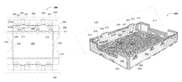
- FIG. 1 is a diagram of an exemplary blank for a conventional stackable container.
- FIG. 2 is a diagram of a conventional stackable container.
- FIG. 3 is a diagram of a blank for a stackable container according to an embodiment of the present invention.
- FIG. 4 is a diagram of a blank for a stackable container according to an alternative embodiment of the present invention.
- FIG. 5 is a photograph showing an implementation of a stackable container in accordance with embodiments of the present invention.
- FIG. 6 is a flow diagram showing an exemplary method of making a container in accordance with an embodiment of the present invention.
- Embodiments of the present invention can advantageously provide a reliable and simplified design approach for making a stackable container from a blank whereby the weight-bearing ability of the structure is improved.
- the invention in its various aspects, will be explained in greater detail below with regard to exemplary embodiments.
- an exemplary blank 300 suitable for making a stackable container may have a base 301 having a first pair of opposed base edges 318 (typically, but not necessarily, shorter base edges) and a second pair of opposed base edges 311 (typically, but not necessarily, longer base edges).
- the exemplary blank 300 may be made from any material that can be cut, scored, folded, and assembled in the manner described herein, corrugated board is preferred.
- Such corrugated board generally contains two outer layers of paperboard or cardboard (which generally has a relatively heavy weight), with an inner layer of corrugation (e.g., corrugated paper), but it may contain further layers (e.g., of an external paper or plastic sheet for further support, waterproofing and/or marking, e.g., with advertising and/or identification information; a further inner layer or sheet [e.g., of paper or plastic] between two layers of corrugation; etc.) or contain different materials (e.g., plastic sheet having a relatively high stiffness or modulus of elasticity).
- an inner layer of corrugation e.g., corrugated paper
- further layers e.g., of an external paper or plastic sheet for further support, waterproofing and/or marking, e.g., with advertising and/or identification information
- a further inner layer or sheet e.g., of paper or plastic] between two layers of corrugation; etc.
- different materials e.g., plastic sheet having a relatively high stiffness or modul
- First sidewall structures 310 may each be foldably attached to one of the first base edges 318 .
- Second sidewall structures 320 may each be foldably attached to one of the second base edges 311 .
- a foldable attachment can be an attachment with a perforation, indentation, score, or other suitable form so as to facilitate a folding of one side of the attachment with respect to the other side of the attachment, while maintaining an attachment or connection between the two sides.
- end walls 310 can be folded to approximately 90 degree angles with respect to base 301 to form walls of the stackable container structure, as will be discussed in more detail below.
- Each of the second sidewall structures 320 has a wall flap 302 foldably attached to a base edge 311 , index fold-down flaps 303 and 304 foldably attached to wall flap 302 along a fold line 313 , and inner fold-down flaps 305 , 306 , and 307 foldably attached to wall flap 302 along a fold lines 314 .
- the inner fold-down flaps 305 - 307 and the index fold-down flaps 303 and 304 alternate such that there is an index fold-down flap between each inner fold-down flap along wall flap 302 .
- Wall flap 302 may include one or more holes 317 configured to provide slots for indexing with another stackable container.
- the wall flap 302 and the index fold-down flaps 303 and 304 form index projections configured to fit into the slots 317 .
- the flutes are vertical in the load-bearing wall.
- second sidewall structures 320 may be folded to form the load-bearing wall.
- the flutes of the corrugated board forming the blank should be oriented perpendicularly to fold line 311 .
- the fold lines between the wall flap and the index and inner wall flaps are generally parallel to the fold line between the second sidewall structure and the base (e.g., the first fold line).
- the distance between the first fold line 311 and the second fold line 313 is greater than the distance between the first fold line 311 and the third fold lines 314 (e.g., the height of the folded sidewall).
- the width of the inner fold-down flaps 305 - 307 is substantially equal to a width of the wall flap 302 (e.g., excluding the height of the projection formed by the index fold-down flap).
- the edge of the index fold-down flaps 303 and 304 and edges of inner fold-down flaps 305 - 307 are separated by cut-lines in the blank.
- each index fold-down flap may be separated from its neighboring inner fold-down flaps by such a cut-line.
- Each of the second sidewall structures 320 also includes first extension flaps 308 foldably attached to each of the inner fold-down flaps 305 and 307 closest to the first sidewall structures, along first extension fold lines approximately parallel to the first base edges.
- Second extension flaps 309 are foldably attached to the wall flap 302 at ends closest to the first sidewall structures 310 .
- the first and second extension flaps generally extend beyond lines formed by the base edges 318 .
- Sidewall structure 320 may have one or more holes 315 a in inner fold-down flaps 305 - 307 , and complementary holes 315 b in wall flap 302 .
- holes 315 a and 315 b may be configured to provide an opening for air to flow, for example.
- the width at the top of the holes may be less than the width of the bottom of the holes (e.g., the holes may have a generally triangular shape with an apex nearest the fold line between the wall flap and the inner fold-down flap). This triangular configuration generally provides for improved strength of the folded wall structure along fold lines 314 (e.g., as opposed to round or rectangular air holes in the same position).
- Cutouts 321 may substantially coincide with holes 317 when inner fold-down flaps 305 - 307 are folded onto wall flap 302 . Cutouts 321 may facilitate index projections formed by wall flaps 302 and index fold-down flaps 303 and/or 304 from another stackable container sliding into holes or indexable slots 317 to form a stackable pair of containers, for example.
- blank 300 may include cutouts 316 along the foldable attachment between base 301 and wall flap 302 . Such cutouts 316 may further assist air flow over produce within the assembled container and/or enable access to a lower surface of an overlying stacked container for ease in lifting (e.g., un-stacking) such stacked containers.
- each second sidewall structure 320 has two index flaps 303 and 304 (thus forming two index projections on each of the two sides) and three inner fold-down flaps 305 - 307 , where inner fold down flaps and index flaps alternate along the wall flap 302 .
- Blank 400 includes base 401 and first sidewall structures 410 , as well as second sidewall structures 420 .
- each second sidewall structure 420 has one index fold-down flap 404 between inner fold-down flaps 406 and 407 .
- Base 501 has a first pair of opposed base edges 518 and a second pair of opposed base edges 511 .
- First sidewall structures 510 are foldably attached to the base edges 518 at an angle of from about 90 degrees to about 100 degrees.
- Second sidewall structures 520 generally include a wall flap 502 foldably attached to base edge 511 at an angle of from about 90 degrees to about 100 degrees, index fold-down flaps 503 and 504 foldably attached to the wall flap 502 along fold lines 513 at an angle of about 180 degrees (e.g., folded over wall flap 502 ), and inner fold-down flaps 505 - 507 foldably attached to wall flap 502 along fold lines 514 at an angle of about 180 degrees.
- Sidewall structures 520 may be substantially vertical, or may be inclined at an angle of from 90 to 100 degrees (preferably an angle of from 92 to 95 degrees) to accommodate indexing functionality.
- the inner fold-down flaps 505 - 507 and the index fold-down flaps 503 and 504 alternate such that there is an index fold-down flap between each inner fold-down flap along wall flap 502 .
- Wall flap 502 may include one or more holes 517 configured to provide slots for indexing with another stackable container.
- the wall flap 502 and the index fold-down flaps 503 and 504 form index projections configured to fit into the slots 517 .
- the flutes are vertical (or substantially vertical) in the load-bearing walls.
- second sidewall structures 520 generally comprise the load-bearing wall, so the flutes of the corrugated board forming the blank should be oriented vertically in second sidewall structures 520 .
- fold lines 513 and 514 generally cover a substantial portion of the flute tops when fold-down flaps 503 - 507 are folded over wall flap 502 .
- moisture collection in the load-bearing walls e.g., moisture due to outdoor precipitation, condensation in cold storage, and/or other natural and/or artificial events
- Sidewall structure 520 may have one or more holes 515 through inner fold down flaps 505 - 507 and wall flap 502 , configured to provide an opening for air to flow.
- the width at the top of the holes may be less than the width of the bottom of the holes (e.g., the holes have a generally triangular shape with an apex nearest the fold line between the wall flap and the inner fold-down flap). This triangular configuration generally provides for improved strength of the folded wall structure along fold lines 513 and 514 (e.g., as opposed to round or rectangular air holes in the same position).
- the tops of the wall flaps are generally parallel to the fold line 511 between the second sidewall structure and the base.
- the tops of the wall flap at the fold lines 513 of the index fold-down flaps 503 and 504 are higher than the top of the wall flap at the fold lines 514 of the inner fold-down flaps 505 - 507 .
- the index fold-down flap is folded over the wall flap to form a projection above the top of the wall flap at the fold line of the inner fold-down flaps.
- the heights of the inner fold-down flaps 505 - 507 are substantially equal to a height of the wall flap 502 (e.g., excluding the height of the projection formed by the index fold-down flap).
- Each of the second sidewall structures 520 also include first extension flaps 508 foldably attached at an angle of about 90 degrees to each of the inner fold-down flaps 505 and 507 closest to the first sidewall structures 510 , such that the first extension flaps 508 are parallel to the first sidewall structures.
- Second extension flaps 509 are foldably attached at an angle of about 90 degrees to the wall flaps 502 at ends closest to the first sidewall structures 510 , such that the second extension flaps 509 are parallel to the first extension flaps 508 and to the sidewall structures 510 .
- Surfaces of the fold-down flaps 503 - 507 may be adhesively attached to a surface of the wall flap 502 (e.g., to a surface of wall flap 502 facing the inside of the container).
- a first surface (e.g., a surface facing away from the inside of the container) of each of the second extension flaps 509 may be adhesively attached to a surface (e.g., an inner surface) of one of the first sidewall structures 510 and a surface of each of the first extension flaps 508 may be adhesively attached to a second surface of one of the second extension flaps 509 .
- a first surface of each of the second extension flaps 509 may be adhesively attached to a first surface (e.g., an outer surface) of one of the first sidewall structures 510 and a surface of each of the first extension flaps 508 may be adhesively attached to a second surface (e.g., an inner surface) of one of the first sidewall structures, thus “sandwiching” each first sidewall structure between two extension flaps.
- stackable container blank 300 may be substantially made from corrugated paper product material, for example.
- an adhesive material or glue may be used to secure different portions, flaps, and/or extensions together.
- fold-down flaps 503 - 507 may be glued or otherwise adhesively attached to wall flap 502 .
- extensions 508 may be glued to extensions 509
- extensions 509 may be glued or otherwise adhesively attached to sidewall structure 510 .
- FIG. 5 While the exemplary embodiment shown in FIG. 5 includes a rectangular base and particular angles and extension sizes, one skilled in the art will recognize that other base configurations (e.g., square), wall and extension angles, and wall/extension sizes may also be used in accordance with embodiments. Further, one skilled in the art will recognize that other means of attachment (e.g., besides glue) may also be used in accordance with embodiments.
- a flow diagram showing an exemplary method of making a container in accordance with an embodiment of the present invention is indicated by the general reference character 600 .
- the method begins at step 601 .
- a container blank e.g., a container blank such as blank 300 of FIG. 3 , blank 400 of FIG. 4 , or any other stackable container blank according to the present invention.
- the blank generally has (a) a base having a first pair of opposed base edges (typically, but not necessarily, shorter base edges) and a second pair of opposed base edges (typically, but not necessarily, longer base edges), (b) two first sidewall structures, each first sidewall structure foldably attached to one of the first base edges, and (c) two second sidewall structures, each second sidewall structure foldably attached to one of the second base edges.
- Each of the second sidewall structures (e.g., structures on the longer sides) has (i) a wall flap foldably attached to one of the second base edges along a first fold line, (ii) an index fold-down flap foldably attached to the wall flap along a second fold line, and (iii) a plurality of inner fold-down flaps foldably attached to the wall flap along a third fold line, wherein the index flap and inner fold-down flaps alternate.
- step 603 two opposing first sidewall structures are folded to form angles of about 90 degrees to about 100 degrees with respect to a base of the stackable container blank.
- step 604 each of the two opposing sidewall structures is folded.
- Step 604 includes sub-steps 610 - 612 .
- the wall flap is folded along the first fold line to form an angle of about 90 degrees to about 100 degrees with respect to the base.
- the inner fold-down flaps are folded along the third fold line to form an angle of about 180 degrees with respect to the wall flap.
- step 612 the index fold-down flap(s) are folded along the second fold line to form an angle of about 180 degrees with respect to the wall flap, such that the second fold line projects above the third fold line.
- the blank has first extension flaps foldably attached to each of the inner fold-down flaps closest to the first sidewall structures and second extension flaps foldably attached to the wall flap at an edge closest to the first sidewall structures.
- the method may further include folding the first and second extension flaps at an angle of 90 degrees with respect to the inner fold-down flaps, such that the first and second extension flaps are approximately parallel to the first sidewall structures.
- Step 604 may further include a step of adhesively attaching surfaces of each of the inner and index fold-down flaps to a surface of the wall flap.
- the first surface of each of the second extension flaps may be adhesively attached to a first surface of one of the first sidewall structures, and the first extension flap may be adhesively attached to a second surface of one of the second extension flaps (e.g., sandwiching each second extension flap between a first sidewall structure and a first extension flap).
- the method may include adhesively attaching a surface of each of the first extension flaps to a second surface of one of the first sidewall structures (e.g., sandwiching each second sidewall structure between first and second extension flaps).
- the adhesive attaching can be done by applying an adhesive substance or glue to a surface of either of the first and second pairs of opposed walls, for example.
- a machine e.g., a box erector
- a single machine may be used to form the blank (e.g., a die cutter and/or a score) and then to form the stackable container (e.g., compressor machines to push portions and/or extensions together) from the blank.
- several machines can be used to perform various portions of flow 600 .
- embodiments of the present invention can advantageously provide a reliable design approach for making a stackable container from a blank, whereby the weight-bearing ability and/or stackability of the container is improved, while also covering flutes on the load-bearing wall, thereby reducing moisture collection.
Landscapes
- Engineering & Computer Science (AREA)
- Mechanical Engineering (AREA)
- Cartons (AREA)
Abstract
Description
Claims (34)
Priority Applications (1)
| Application Number | Priority Date | Filing Date | Title |
|---|---|---|---|
| US12/183,016 US8079474B1 (en) | 2007-07-30 | 2008-07-30 | Stackable container and method for making the same |
Applications Claiming Priority (2)
| Application Number | Priority Date | Filing Date | Title |
|---|---|---|---|
| US95281207P | 2007-07-30 | 2007-07-30 | |
| US12/183,016 US8079474B1 (en) | 2007-07-30 | 2008-07-30 | Stackable container and method for making the same |
Publications (1)
| Publication Number | Publication Date |
|---|---|
| US8079474B1 true US8079474B1 (en) | 2011-12-20 |
Family
ID=45219136
Family Applications (1)
| Application Number | Title | Priority Date | Filing Date |
|---|---|---|---|
| US12/183,016 Active 2030-03-10 US8079474B1 (en) | 2007-07-30 | 2008-07-30 | Stackable container and method for making the same |
Country Status (1)
| Country | Link |
|---|---|
| US (1) | US8079474B1 (en) |
Cited By (25)
| Publication number | Priority date | Publication date | Assignee | Title |
|---|---|---|---|---|
| US20130048704A1 (en) * | 2011-08-30 | 2013-02-28 | William H. Lewis | Article-transport container |
| USD679094S1 (en) * | 2011-05-10 | 2013-04-02 | William Scott | Box |
| USD690106S1 (en) | 2012-04-28 | 2013-09-24 | William Mitchell Scott | Carrying tote |
| USD690107S1 (en) | 2012-04-28 | 2013-09-24 | William Mitchell Scott | Carrying tote |
| USD690105S1 (en) | 2012-04-28 | 2013-09-24 | William Mitchell Scott | Carrying tote |
| USD698152S1 (en) | 2011-05-10 | 2014-01-28 | William Mitchell Scott | Box |
| USD711108S1 (en) | 2011-05-09 | 2014-08-19 | William Mitchell Scott | Box |
| USD711738S1 (en) | 2012-04-27 | 2014-08-26 | William Mitchell Scott | Box |
| USD712476S1 (en) | 2012-11-09 | 2014-09-02 | William Mitchell Scott | Document holder |
| USD712475S1 (en) | 2012-11-09 | 2014-09-02 | William Mitchell Scott | Document holder |
| USD712251S1 (en) | 2011-05-10 | 2014-09-02 | William Mitchell Scott | Box |
| USD720539S1 (en) | 2012-09-07 | 2015-01-06 | William Mitchell Scott | Box |
| USD721495S1 (en) | 2012-09-07 | 2015-01-27 | William Mitchell Scott | Box |
| US9051075B2 (en) | 2012-09-07 | 2015-06-09 | William M. Scott | Corrugated container box and blank |
| US9156578B2 (en) | 2012-02-03 | 2015-10-13 | Rock-Tenn Shared Services, Llc | Reinforced polygonal containers and blanks for making the same |
| USD740564S1 (en) | 2012-04-30 | 2015-10-13 | William Mitchell Scott | Box |
| US9242759B2 (en) | 2011-04-25 | 2016-01-26 | William Mitchell Scott | Container with grips |
| US9352888B2 (en) | 2012-09-07 | 2016-05-31 | William Mitchell Scott | Shipping container with grips and locking ports |
| USD811788S1 (en) * | 2014-06-03 | 2018-03-06 | Vanguard Packaging, Inc. | Display tray |
| USD823109S1 (en) * | 2016-06-24 | 2018-07-17 | Visy R & D Pty Ltd | Blank for a tray |
| USD825329S1 (en) * | 2016-05-06 | 2018-08-14 | Visy R & D Pty Ltd | Blank for forming a tray |
| USD840807S1 (en) * | 2016-06-24 | 2019-02-19 | Visy R & D Pty Ltd | Blank for forming a tray |
| USD842098S1 (en) * | 2016-07-19 | 2019-03-05 | Visy R & D Pty Ltd | Blank for forming a tray |
| US20230278747A1 (en) * | 2022-03-02 | 2023-09-07 | Westrock Shared Services, Llc | Corner configurations for tray containers |
| US20240228104A1 (en) * | 2023-01-06 | 2024-07-11 | Westrock Shared Services, Llc | Produce trays with reinforced tabs |
Citations (5)
| Publication number | Priority date | Publication date | Assignee | Title |
|---|---|---|---|---|
| US4905834A (en) | 1988-05-30 | 1990-03-06 | Iberoamericana Del Embalaje, S.A. | Stackable container |
| US5860590A (en) | 1995-04-11 | 1999-01-19 | Carter Holt Harvey Limited | Stackable container of paperboard |
| US20020125308A1 (en) | 2001-03-12 | 2002-09-12 | Mcleod Michael B. | Stackable shipping container |
| US6604675B2 (en) * | 1999-10-22 | 2003-08-12 | Packaging Corporation Of America | Displayable produce container and method for making the same |
| US6641032B1 (en) | 2002-05-08 | 2003-11-04 | Fruit Growers Supply Company | Stackable container with reinforced corner |
-
2008
- 2008-07-30 US US12/183,016 patent/US8079474B1/en active Active
Patent Citations (5)
| Publication number | Priority date | Publication date | Assignee | Title |
|---|---|---|---|---|
| US4905834A (en) | 1988-05-30 | 1990-03-06 | Iberoamericana Del Embalaje, S.A. | Stackable container |
| US5860590A (en) | 1995-04-11 | 1999-01-19 | Carter Holt Harvey Limited | Stackable container of paperboard |
| US6604675B2 (en) * | 1999-10-22 | 2003-08-12 | Packaging Corporation Of America | Displayable produce container and method for making the same |
| US20020125308A1 (en) | 2001-03-12 | 2002-09-12 | Mcleod Michael B. | Stackable shipping container |
| US6641032B1 (en) | 2002-05-08 | 2003-11-04 | Fruit Growers Supply Company | Stackable container with reinforced corner |
Cited By (28)
| Publication number | Priority date | Publication date | Assignee | Title |
|---|---|---|---|---|
| US9242759B2 (en) | 2011-04-25 | 2016-01-26 | William Mitchell Scott | Container with grips |
| USD711108S1 (en) | 2011-05-09 | 2014-08-19 | William Mitchell Scott | Box |
| USD709704S1 (en) | 2011-05-10 | 2014-07-29 | William Mitchell Scott | Box |
| USD698152S1 (en) | 2011-05-10 | 2014-01-28 | William Mitchell Scott | Box |
| USD679094S1 (en) * | 2011-05-10 | 2013-04-02 | William Scott | Box |
| USD712251S1 (en) | 2011-05-10 | 2014-09-02 | William Mitchell Scott | Box |
| US20130048704A1 (en) * | 2011-08-30 | 2013-02-28 | William H. Lewis | Article-transport container |
| US9156578B2 (en) | 2012-02-03 | 2015-10-13 | Rock-Tenn Shared Services, Llc | Reinforced polygonal containers and blanks for making the same |
| USD711738S1 (en) | 2012-04-27 | 2014-08-26 | William Mitchell Scott | Box |
| USD690107S1 (en) | 2012-04-28 | 2013-09-24 | William Mitchell Scott | Carrying tote |
| USD690105S1 (en) | 2012-04-28 | 2013-09-24 | William Mitchell Scott | Carrying tote |
| USD690106S1 (en) | 2012-04-28 | 2013-09-24 | William Mitchell Scott | Carrying tote |
| USD740564S1 (en) | 2012-04-30 | 2015-10-13 | William Mitchell Scott | Box |
| US9051075B2 (en) | 2012-09-07 | 2015-06-09 | William M. Scott | Corrugated container box and blank |
| USD720539S1 (en) | 2012-09-07 | 2015-01-06 | William Mitchell Scott | Box |
| US9352888B2 (en) | 2012-09-07 | 2016-05-31 | William Mitchell Scott | Shipping container with grips and locking ports |
| USD721495S1 (en) | 2012-09-07 | 2015-01-27 | William Mitchell Scott | Box |
| USD712475S1 (en) | 2012-11-09 | 2014-09-02 | William Mitchell Scott | Document holder |
| USD712476S1 (en) | 2012-11-09 | 2014-09-02 | William Mitchell Scott | Document holder |
| USD811788S1 (en) * | 2014-06-03 | 2018-03-06 | Vanguard Packaging, Inc. | Display tray |
| USD825329S1 (en) * | 2016-05-06 | 2018-08-14 | Visy R & D Pty Ltd | Blank for forming a tray |
| USD823109S1 (en) * | 2016-06-24 | 2018-07-17 | Visy R & D Pty Ltd | Blank for a tray |
| USD840807S1 (en) * | 2016-06-24 | 2019-02-19 | Visy R & D Pty Ltd | Blank for forming a tray |
| USD842098S1 (en) * | 2016-07-19 | 2019-03-05 | Visy R & D Pty Ltd | Blank for forming a tray |
| US20230278747A1 (en) * | 2022-03-02 | 2023-09-07 | Westrock Shared Services, Llc | Corner configurations for tray containers |
| US12252305B2 (en) * | 2022-03-02 | 2025-03-18 | Westrock Shared Services, Llc | Corner configurations for tray containers |
| US20240228104A1 (en) * | 2023-01-06 | 2024-07-11 | Westrock Shared Services, Llc | Produce trays with reinforced tabs |
| US12434878B2 (en) * | 2023-01-06 | 2025-10-07 | Westrock Shared Services, Llc | Produce trays with reinforced tabs |
Similar Documents
| Publication | Publication Date | Title |
|---|---|---|
| US8079474B1 (en) | Stackable container and method for making the same | |
| US7290696B2 (en) | Container with reinforced corner panels and the associated container blank | |
| US9242758B2 (en) | Polygonal containers having a locking bottom and blanks and methods for forming the same | |
| US5588585A (en) | Automatic set-up carton with corner posts | |
| US5860590A (en) | Stackable container of paperboard | |
| US6508395B2 (en) | Stackable shipping container | |
| US6719191B1 (en) | Stackable bliss-type container | |
| US9656777B2 (en) | Stackable container blank, stackable container, and method for making the same | |
| US6460758B1 (en) | Trays | |
| US20090272789A1 (en) | Stackable and indexable packing tray | |
| US7841511B2 (en) | Carton bottom closure | |
| CA2990604C (en) | Container with a reinforcement structure and method of forming the same | |
| CA2487524C (en) | Carton with corner post construction | |
| US20070000986A1 (en) | Container having an "L" corner assembly and associated container blank | |
| US7473215B2 (en) | Shipping container and method of manufacturing same | |
| US20250058928A1 (en) | Container With Divider | |
| US20190118995A1 (en) | Product tray | |
| US6443358B1 (en) | Stackable container | |
| US20060157484A1 (en) | Carton, blank therefor and packing arrangement thereof | |
| US5513753A (en) | Top carrier for gable cartons | |
| AU2002317525B1 (en) | A Container | |
| AU2001265389B2 (en) | Stackable container | |
| WO2013121343A1 (en) | Stackable container and blank for construction thereof | |
| CA2669368C (en) | Stackable and indexable packing tray | |
| AU2001265389A1 (en) | Stackable container |
Legal Events
| Date | Code | Title | Description |
|---|---|---|---|
| AS | Assignment |
Owner name: MAXCO SUPPLY, INC., CALIFORNIA Free format text: ASSIGNMENT OF ASSIGNORS INTEREST;ASSIGNOR:FLAMING, MAX;REEL/FRAME:021324/0434 Effective date: 20080730 |
|
| STCF | Information on status: patent grant |
Free format text: PATENTED CASE |
|
| FPAY | Fee payment |
Year of fee payment: 4 |
|
| MAFP | Maintenance fee payment |
Free format text: PAYMENT OF MAINTENANCE FEE, 8TH YR, SMALL ENTITY (ORIGINAL EVENT CODE: M2552); ENTITY STATUS OF PATENT OWNER: SMALL ENTITY Year of fee payment: 8 |
|
| MAFP | Maintenance fee payment |
Free format text: PAYMENT OF MAINTENANCE FEE, 12TH YR, SMALL ENTITY (ORIGINAL EVENT CODE: M2553); ENTITY STATUS OF PATENT OWNER: SMALL ENTITY Year of fee payment: 12 |
|
| AS | Assignment |
Owner name: WELLS FARGO BANK, NATIONAL ASSOCIATION, CALIFORNIA Free format text: SECURITY INTEREST;ASSIGNOR:MAXCO SUPPLY, INC.;REEL/FRAME:070118/0465 Effective date: 20250205 |