US8079414B2 - Electromagnetic free point tool and methods of use - Google Patents
Electromagnetic free point tool and methods of use Download PDFInfo
- Publication number
- US8079414B2 US8079414B2 US12/421,241 US42124109A US8079414B2 US 8079414 B2 US8079414 B2 US 8079414B2 US 42124109 A US42124109 A US 42124109A US 8079414 B2 US8079414 B2 US 8079414B2
- Authority
- US
- United States
- Prior art keywords
- pipe
- free point
- coil
- receiver
- housing
- Prior art date
- Legal status (The legal status is an assumption and is not a legal conclusion. Google has not performed a legal analysis and makes no representation as to the accuracy of the status listed.)
- Active, expires
Links
Images


Classifications
-
- E—FIXED CONSTRUCTIONS
- E21—EARTH DRILLING; MINING
- E21B—EARTH DRILLING, e.g. DEEP DRILLING; OBTAINING OIL, GAS, WATER, SOLUBLE OR MELTABLE MATERIALS OR A SLURRY OF MINERALS FROM WELLS
- E21B47/00—Survey of boreholes or wells
- E21B47/09—Locating or determining the position of objects in boreholes or wells, e.g. the position of an extending arm; Identifying the free or blocked portions of pipes
Definitions
- the present application relates to electromagnetic free point tools. More particularly, methods and devices are provided for determining the free point of a downhole pipe in a wellbore by magnetic permeability measurements utilizing amplitude or phase change and lock-in amplifiers.
- the drill pipe can become stuck for any number of reasons such as differential well bore pressure, key seating, sand bridging, well bore collapse, and swelling of the borehole to name a few.
- the stuck drill pipe must then be removed before the well bore can be repaired and drilling operations continue.
- the first step in removing the stuck pipe is to determine where in the well it is stuck so that the section of pipe above this point (the free pipe) can be removed.
- a low resolution method involves measuring how much the pipe twists or stretches when a particular torque or force is applied to the pipe at or near the surface. Knowing the elastic properties of the drill pipe allows one to calculate the length of pipe that is free to within several hundreds of feet.
- a “free point tool” is employed. The most common type are mechanical tools, which are lowered within the pipe with temporary anchors that extend to lock both ends of the tool to the borehole. Sensors within the tool detect relative movement of the tool ends when the drill pipe is twisted or stretched. If the tool is anchored below the stuck point no differential motion is detected. Gradually, the location of the stuck point is located once the tool detects differential movement. The same procedure could also be repeated in reverse, moving the tool downwards as well.
- Another common type of tool for determining differential movement is similar to the aforementioned tool except that strong springs are used to hold the tool in position.
- U.S. Pat. No. 4,708,204 describes an example of such a wireline tool.
- Such tools basically consist of two coils separated by a fixed distance on a mandrel. An oscillating voltage would be applied to the first coil (i.e. a transmitter coil) and the induced current in a second coil (i.e. a receiver coil) would be measured relative to the applied voltage of the first coil.
- a log of receiver coil phase or amplitude relative to the transmitter coil phase may be generated.
- a second log may be generated during a second pass of the tool after the pipe has been stressed. The two logs can then be compared so as to determine the stuck point of the pipe, as the two logs will be more or less identical below the stuck point and will diverge above the stuck point.
- the present application relates to electromagnetic free point tools. More particularly, methods and devices are provided for determining the free point of a downhole pipe in a wellbore by magnetic permeability measurements.
- an electromagnetic free point tool comprises an elongated, tubular housing, with one or more transmitter coils carried by the housing and one or more receiver coils carried by the housing, each coil spaced apart from one another.
- the tool further includes a power source for applying an oscillating voltage to the one or more transmitter coils. The oscillating voltage then induces a current in the receiver coil(s), which induced current is measured by electronics carried by the housing.
- the tool makes two runs along a length of pipe under investigation.
- the current is plotted on a log graph for each of the runs and compared.
- the pipe under investigation is unstressed, while in the other run, an external force, such as an axial or torsional force, is placed on the pipe during the run.
- An amplitude or phase change in the measured current can represent a point of interest, such as a stuck point.
- At least one of the coils is axially adjustable in position within the tool to permit the relative distance between coils to be adjusted. This permits the tool to be optimized for performance under various conditions, thereby eliminating the need for multiple tools.
- a log of the amplitude or phase is generated while passing the tool through a length of unstressed pipe. This process may be repeated while applying a stress to the pipe to generate a second log.
- the free point of the pipe may be ascertained by determining when and where the two logs diverge.
- This method can also be used to locate collars in a pipe string and to measure pipe thickness along a pipe string.
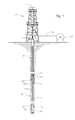
- FIG. 1 illustrates a cross-section of a wellbore with the tool of the invention deployed therein.
- FIG. 2 illustrates a cross-section of a downhole electromagnetic free point tool in accordance with one embodiment of the present invention.
- FIG. 3 illustrates a cross-section of a downhole electromagnetic free point tool in accordance with another embodiment of the present invention.
- FIG. 4 illustrates an electrical schematic of a downhole electromagnetic free point tool in accordance with one embodiment of the present invention.
- FIG. 5 a illustrates free point tool data of electromagnetic phase shift over varied frequency and coil spacing ranges between stressed and unstressed 5′′ pipe.
- FIG. 5 b illustrates free point tool data of electromagnetic amplitude change over varied frequency and coil spacing ranges between stressed and unstressed 5′′ pipe.
- FIG. 6 a illustrates free point tool data of electromagnetic phase shift over varied frequency and coil spacing ranges between stressed and unstressed 27 ⁇ 8′′ pipe.
- FIG. 6 b illustrates free point tool data of electromagnetic amplitude change over varied frequency and coil spacing ranges between stressed and unstressed 27 ⁇ 8′′ pipe.
- FIG. 7 a illustrates the significant difference in phase shift that can exist over a frequency range of a free point tool disposed in a 5′′ pipe and a 27 ⁇ 8′′ pipe.
- FIG. 7 b illustrates the convergence of amplitude change that exists over a frequency range of a free point tool disposed in a 5′′ pipe and a 27 ⁇ 8′′ pipe.
- the present application relates to electromagnetic free point tools. More particularly, methods and devices are provided for determining the free point of a downhole pipe in a wellbore from magnetic permeability measurements.
- electromagnetic free point tools of the present invention comprise a housing, one or more transmitter coils disposed within the housing, one or more receiver coils disposed within the housing, each coil spaced apart from one another, a power source electrically coupled to the one or more transmitter coils for applying an oscillating voltage to the transmitter coil(s) at fixed, adjustable or multiple frequencies so as to induce one or more currents in the receiver coil(s), and electronics for measuring the induced current in each of the receiver coils.
- a log of the phase can be generated by passing the electromagnetic free point tool through a length of unstressed downhole pipe. This process may be repeated after applying a stress to the pipe to generate a second log of the phase. By comparing the phase of the first log to the phase of the second log, the free point of the pipe may be ascertained by determining the point at which the two logs diverge.
- the amplitude change of the voltage induced in the receiver coil or coils is utilized to identify a stuck point rather than the phase change, particularly in a tool to be utilized in a range of pipe diameters.
- Advantages of certain embodiments include, but are not limited to, speed of execution of the method for determining the free point of a downhole pipe, ease of interpretation of the results, efficiency, accuracy, and precision of the methods herein, and the ability to determine the free point of a downhole pipe that is disposed within the confines of one or more larger diameter pipes.
- the tool of the invention can be utilized to measure pipe thickness or alternatively, as a collar locator.
- FIG. 1 illustrates a drilling rig 10 disposed atop a borehole 12 .
- the rig 10 includes draw works 11 which support a drill string 14 .
- the drill string 14 consists of a plurality of series connected sections of drilling pipe 16 which are threaded end to end in a conventional fashion.
- a drilling bit 18 is located at the lower end of the drilling string 14 .
- the drilling bit 18 serves to carve the borehole 12 through the earth formations 20 .
- Metal casing 22 is shown positioned in the borehole 12 near the surface to maintain the integrity of the upper portion of the borehole 12 .
- An annulus 24 is formed between the drilling pipe 16 and the side walls 26 of borehole 12 and serves as a return flow path for drilling fluid pumped down drilling pipe 16 .
- FIG. 1 is a cave-in of a portion of the wall 26 of borehole 12 around the drill string 14 so that the pipe section 16 a is stuck in the open hole as illustrated at point S 1 .
- S 2 is debris that has become lodged in the annulus 24 between metal casing 22 and drill string 14 so that the pipe section 16 b is stuck in the cased hole.
- the system of the invention functions to locate stuck points such as S 1 and S 2 along the length of the borehole 12 and drill string 14 utilizing a single free point tool sufficiently robust to identify stuck points in both cased and uncased portions of borehole 12 , thereby permitting all of the free sections of drill pipe 16 above the stuck pipe joint, which is immovably jammed in the borehole 12 , to be removed. Once all of the pipe above the freepoint S is removed, equipment well known in the art can be brought into the borehole 12 to free joint 15 and thereafter resume the drilling operation.
- the system of the present invention is a freepoint tool 100 which is preferably lowered into borehole 12 on a wireline 30 through the central passageway in the drill string 14 .
- the necessary wireline vehicles 32 , guide pulleys and the like are positioned over the borehole at the well head in a conventional fashion to operate the tool 100 while still controlling the weight on the bit 18 and drill string 14 by conventional means.
- the wireline is conventional and consists of an armored cable with a single or multiple conducting wires which provides both a mechanical and electrical connection between the tool 100 and the wireline control and monitoring equipment at the surface.
- the tool 100 descends down through the central aperture in the drilling string 14 from the wellhead in order to locate the stuck point S through measurable changes in the physical characteristics of the pipe related thereto.
- wireline 30 provides power and surface communications to tool 100 in the conventional manner.
- tool 100 may be lowered on a non-conducting vehicle such as slickline, coiled tubing or other device, and in such case, tool 100 may be provided with local power, communications and local memory to store the acquired data for subsequent read-out at the surface.
- free point tool 100 comprises housing 170 , mandrel 180 , transmitter coil 110 , first receiver coil 130 , second receiver coil 140 , and electronics 150 & 160 .
- Mandrel 180 provides a member about which other elements in housing 170 may be disposed. In certain embodiments, mandrel 180 allows elements of electromagnetic free point tool 100 to be centered or otherwise positioned at fixed points within housing 170 , while in other embodiments of the invention, the position of such elements may be adjustable along the length of mandrel 180 .
- Transmitter electronics 160 applies an oscillating voltage to transmitter coil 110 .
- First receiver coil 130 and second receiver coil 140 are spaced apart from one another and from transmitter coil 110 .
- the oscillating current of transmitter coil 110 induces a corresponding current in first receiver coil 130 and second receiver coil 140 .
- Electronics 150 is communicatively coupled to first receiver coil 130 and second receiver coil 140 and measures the induced current in each receiver coil 130 and 140 .
- tool 100 has a single receiver coil 130 and the spacing between the transmitter coil 110 and the receiver coil 130 is determined based on maximizing the observed change in the voltage amplitude in the receiver coil over as wide a range of frequencies as possible. This is determined by making measurements in stressed and unstressed pipe over the desired frequency range for each coil spacing. In addition, the measurements are repeated in different standard diameter drill pipe, such as 5′′ pipe or 27 ⁇ 8′′ pipe.
- tool 100 has a first receiver coil 130 spaced apart a predetermined distance from transmitter coil 110 based on optimization of tool 100 for use with a 5′′ pipe and a second receiver coil 140 spaced apart a predetermined distance from transmitter coil 110 based on optimization of tool 100 for use with a 27 ⁇ 8′′ pipe, it being understood from the graphs referenced in FIGS. 6 , 7 and 8 that use of the tool 100 is optimized in differing diameter pipes by providing different transmitter-receiver coil spacing.
- the tool can be optimized for both single string measurements, i.e., when the pipe string under investigation is in an open hole, and multiple string measurements, i.e., when the pipe string under investigation is in a cased hole.
- one or more coils 110 , 130 , 140 may be moveable along mandrel 180 so as to provide the ability to adjust the spacing between coils in order to maximize the response of tool 100 for a given set of conditions, which condition variables may include, but are not limited to, pipe diameter and operating frequency.
- condition variables may include, but are not limited to, pipe diameter and operating frequency.
- a receiver coil may be axially moved along mandrel 180 until the spacing between the receiver coil and the transmitter coil is approximately 8′′, thereby maximizing the amplitude change that will occur when tool is operated at 120 Hz and is disposed in a 27 ⁇ 8′′ pipe string (See FIG. 7 b ).
- a transmitter coil may be axially moved along mandrel 180 until the spacing between the receiver coil and the transmitter coil is approximately 16′′, thereby maximizing the amplitude change that will occur when tool is operated at 90 Hz and is disposed in a 5′′ pipe string (See FIG. 6 b ).
- electromagnetic free point tool 100 may then perform these measurements while traversing an axial length within a downhole pipe.
- a log can be generated of the phase or amplitude as a function of distance traversed by electromagnetic free point tool 100 .
- the downhole pipe is stressed at or near the surface, either by applying a torsional stress, a stress in tension, or a combination thereof.
- electromagnetic free point tool 100 repeats the aforementioned measurements along at least a portion of the distance previously traversed in the downhole pipe. Because stressing a pipe will affect the magnetic permeability of the pipe, repeating the phase or amplitude measurements along the stressed length of pipe will yield a different log of phase or amplitude measurements than the previous log of measurements of the unstressed pipe.
- the subsequent phase or amplitude logs of the pipe below the free point i.e. the stuck pipe
- the foregoing system functions equally well in cases of “partial sticking” where a pipe section may be movable, but constrained in some fashion.
- the electromagnetic free point tool 100 could generate a log of the pipe when stressed first and then, subsequently generate a log of the pipe when unstressed.
- any number of receiver coils could be used at different fixed distances from the transmitter coil, including, but not limited to, coil spacings from about 5 inches to about 24 inches, and in certain embodiments from about 6 inches to about 16 inches.
- one or more of the coils may be adapted to automatically displace axially within housing 170 so as to measure phase shifts or amplitude changes at different spacings between coils.
- Receiver electronics 150 comprises memory 152 , CPU 154 , and power source 156 .
- CPU 154 receives and processes measurement data, which may then be stored in local memory 152 or communicated to the surface via the logging cable 30 .
- Power source 152 provides power to electromagnetic free point tool 100 , including supplying power to generate the oscillating voltage applied to transmitter coil 110 .
- Transmitter electronics 160 comprises a signal generator 164 for generating an an oscillating current in transmitter coil 110 .
- signal generator 164 is an oscillator.
- a phase sensitive detector or “lock-in amplifier” may be used for increased sensitivity, stability and noise immunity may also be provided.
- the phase shift or amplitude change that is likely to occur about a free point is comparatively small.
- the lock-in amplifier of the invention achieves this by acting as a narrow bandpass filter which removes much of the unwanted noise while allowing the desired signal which is to be measured.
- the frequency of the signal to be measured and hence the pass band region of the filter is set by a reference signal, namely the signal generated by the signal generator 164 , which is supplied to the lock-in amplifier along with the unknown signal.
- FIG. 3 illustrates a cross-section of a downhole electromagnetic free point tool in accordance with another embodiment of the present invention.
- the embodiment depicted in FIG. 3 is identical to FIG. 2 , except that electromagnetic free point tool 200 comprises two transmitter coils instead of one transmitter coil.
- first transmitter coil 210 and second transmitter coil induce a current in receiver coil 240 .
- a plurality of transmitter coils may be used with one receiver coil instead of one transmitter coil being used in conjunction with a plurality of receiver coils.
- any additional number of transmitter coils and receiver coils could be used in conjunction with electromagnetic free point tool 200 .
- the coil spacing between the various coils of tool 200 may be fixed or adjustable to accommodate the various operating parameters of the tool.
- tools 100 and 200 may be operated a multiple, simultaneous or adjustable frequencies in order to further optimize tool results over a range of operating conditions.
- FIG. 4 illustrates an electrical schematic of a downhole electromagnetic free point tool in accordance with one embodiment of the present invention.
- Signal generator 306 generates an oscillating voltage that is amplified by amplifier 308 and applied to transmitter coil 310 so as to propagate an electromagnetic wave towards the pipe string under investigation. Said electromagnetic wave creates eddy currents in the pipe string. The eddy currents give rise to electromagnetic fields that induce currents in both receiver coil 330 and receiver coil 340 . Relevant oscillating frequencies suitable for use with certain embodiments of the present invention include, but are not limited to, about 30 to about 150 Hz. The induced currents arising from the eddy currents in the pipe are then amplified by amplifiers 332 and 342 respectively.
- Phase sensitive detectors 344 are provided to filter noise and determine the phase or amplitude of the induced currents in receiver coils 330 and 340 relative to the applied oscillating voltage of transmitter coil 310 . To accomplish this, the original amplified signal from signal generator 306 is provided to phase sensitive detectors 334 and 344 as a reference signal. In any event, phase or amplitude data may be transmitted directly to the surface via telemetry 362 or stored locally in memory 352 and then communicated to the surface via telemetry 362 (or other methods known in the industry), where the data and measurements may be interpreted by skilled artisans to identify stuck points or other points of interest (such as collars, etc.)
- the terms, “adapted to” and “configured to” refer to mechanical or structural connections between elements to allow the elements to cooperate to provide the described effect; these terms also refer to operational capabilities of electrical elements such as analog or digital computers or application specific devices (such as an application specific integrated circuits (ASIC)) that are programmed to perform a sequel to provide an output in response to given input signals.
- ASIC application specific integrated circuits
- FIGS. 5 a and 5 b show how variations in coil spacing and frequency affect the changes in signal phase and amplitude, respectively, observed when comparing measurements made in a 5-in pipe that is unstressed ( FIG. 5 a ) with measurements made in the same pipe that is placed under stress, either torsional, longitudinal or a combination ( FIG. 5 b ).
- FIGS. 6 a and 6 b are similar plots for a 27 ⁇ 8-in diameter pipe. The object is to identify a subset of conditions such that, for a fixed coil spacing, the response of the tool is relatively insensitive to the operating frequency resulting in the most robust measurement possible. Thus, in FIG. 5 b , it is seen that the amplitude change due to the applied stress is most pronounced for operating frequencies between 50 and 150 Hz when the transmitter to receiver coil spacing is 12 inches.
- coil spacings other than 12 inches can yield greater changes in phase or amplitude under particular combinations of pipe size and operating frequency.
- FIGS. 7 a and 7 b represent two-dimensional slices through the data plotted in FIGS. 5 and 6 and illustrate the difference between phase shift measurements and amplitude changes over a range of frequencies for a free point tool disposed in 5′′ pipe and 27 ⁇ 8′′ pipe, where the coil spacing is held constant at 12′′.
- FIG. 7 a shows the signal phase shift varying relatively slowly with frequency in the 27 ⁇ 8-in pipe but changes more dramatically in the 5-in pipe.
- the signal amplitudes plotted in FIG. 7 b are more nearly constant as the frequency changes for both pipe sizes.
- a free point tool constructed with a coil spacing of 12 inches can provide useful amplitude measurements over a range of pipe sizes that will be relatively insensitive to changes in operating frequency.
- FIG. 7 a it can be seen that there are significant differences in phase shift that can exist over a frequency range of a free point tool disposed in a 5′′ pipe and a 27 ⁇ 8′′ pipe with a fixed coil spacing.
- FIG. 7 b it can be seen that under the same conditions, the amplitude change between data collected from a 5′′ pipe and a 27 ⁇ 8′′ pipe tend to converge and track one another closely.
- These graphs illustrate the desirability to utilize amplitude change in identifying stuck points for tools intended to be used in a variety of pipe sizes.
- the use of amplitude change in this regard is not as sensitive to certain parameters, such as pipe size or frequency, as is phase shift. As is illustrated, phase shifts can vary dramatically with a changing pipe size.
- Amplitude measurements are less sensitive to these varied parameters and tend to yield a much more uniform or constant response as parameters change.
- a tool with a fixed coil spacing should utilize amplitude change of the reflected electromagnetic signal from stressed and unstressed pipes to identify the stuck points.
- tool 100 , 200 can be utilized to measure wall thickness of the pipe in which it is disposed.
- amplitude or phase over the pipe length is determined. Assuming that permeability and electrical conductivity are substantially constant, changes in phase or amplitude can be utilized to identify changes in the thickness of the pipe, which those skilled in the art will appreciate can be used to detect corrosion, irregularities and other conditions of the pipe.
- collars are simply thicker portions of a pipe, collars can be identified utilizing this same technique.
Abstract
Description
Claims (35)
Priority Applications (1)
| Application Number | Priority Date | Filing Date | Title |
|---|---|---|---|
| US12/421,241 US8079414B2 (en) | 2009-04-09 | 2009-04-09 | Electromagnetic free point tool and methods of use |
Applications Claiming Priority (1)
| Application Number | Priority Date | Filing Date | Title |
|---|---|---|---|
| US12/421,241 US8079414B2 (en) | 2009-04-09 | 2009-04-09 | Electromagnetic free point tool and methods of use |
Publications (2)
| Publication Number | Publication Date |
|---|---|
| US20100257927A1 US20100257927A1 (en) | 2010-10-14 |
| US8079414B2 true US8079414B2 (en) | 2011-12-20 |
Family
ID=42933262
Family Applications (1)
| Application Number | Title | Priority Date | Filing Date |
|---|---|---|---|
| US12/421,241 Active 2029-12-29 US8079414B2 (en) | 2009-04-09 | 2009-04-09 | Electromagnetic free point tool and methods of use |
Country Status (1)
| Country | Link |
|---|---|
| US (1) | US8079414B2 (en) |
Cited By (11)
| Publication number | Priority date | Publication date | Assignee | Title |
|---|---|---|---|---|
| US20120212351A1 (en) * | 2011-02-17 | 2012-08-23 | Hu Wenbao | High-power electromagnetic pulse launcher in well |
| US9255851B2 (en) | 2012-12-21 | 2016-02-09 | Ge Oil & Gas Esp, Inc. | Enhanced device for determining the location of induced stress in stuck borehole tubulars |
| US9310338B2 (en) * | 2010-10-14 | 2016-04-12 | Halliburton Energy Services, Inc. | Method for measuring remote field eddy current thickness in multiple tubular configuration |
| US10571242B2 (en) | 2016-08-12 | 2020-02-25 | Halliburton Energy Services, Inc. | Elimination of residual magnetism effect in eddy current based inspection of pipes |
| US10883810B2 (en) | 2019-04-24 | 2021-01-05 | Saudi Arabian Oil Company | Subterranean well torpedo system |
| US10955264B2 (en) | 2018-01-24 | 2021-03-23 | Saudi Arabian Oil Company | Fiber optic line for monitoring of well operations |
| US10995574B2 (en) | 2019-04-24 | 2021-05-04 | Saudi Arabian Oil Company | Subterranean well thrust-propelled torpedo deployment system and method |
| US10996366B2 (en) | 2015-09-17 | 2021-05-04 | Halliburton Energy Services, Inc. | Determining permeablility based on collar responses |
| US11287545B2 (en) | 2019-12-26 | 2022-03-29 | Baker Hughes Oilfield Operations Llc | Magnetic freepoint indicator tool |
| US11365958B2 (en) | 2019-04-24 | 2022-06-21 | Saudi Arabian Oil Company | Subterranean well torpedo distributed acoustic sensing system and method |
| US11840902B2 (en) | 2021-04-19 | 2023-12-12 | Ardyne Holdings Limited | Well abandonment |
Families Citing this family (4)
| Publication number | Priority date | Publication date | Assignee | Title |
|---|---|---|---|---|
| US20140183963A1 (en) * | 2012-12-28 | 2014-07-03 | Kenneth B. Wilson | Power Transmission in Drilling and related Operations using structural members as the Transmission Line |
| US10662760B2 (en) * | 2015-12-09 | 2020-05-26 | Halliburton Energy Services, Inc. | Eddy-current responses in nested pipes |
| NO343697B1 (en) * | 2017-05-23 | 2019-05-13 | Altus Intervention Tech As | Method and apparatus for performing a survey of tubing which is stuck in a borehole, e.g. for determining a free point |
| US11339648B2 (en) * | 2019-05-15 | 2022-05-24 | Baker Hughes Oilfield Operations Llc | Systems and methods for wireless communication in a well |
Citations (14)
| Publication number | Priority date | Publication date | Assignee | Title |
|---|---|---|---|---|
| US2698920A (en) * | 1951-03-06 | 1955-01-04 | Ford Alexander Corp | Apparatus for exploring pipe in wells |
| US3085428A (en) * | 1959-07-07 | 1963-04-16 | Electronics Res Corp Of Americ | Methods for determining the movability of conduits |
| US3233170A (en) * | 1961-03-01 | 1966-02-01 | Houston Oil Field Mat Co Inc | Magnetic stuck pipe locator and detonator using a single line to transmit signals |
| US3277363A (en) * | 1961-01-23 | 1966-10-04 | Schlumberger Well Surv Corp | Borehole investigating method and apparatus utilizing magnetic-flux fields induced in a casing pipe lining the borehole |
| US4708204A (en) | 1984-05-04 | 1987-11-24 | Nl Industries, Inc. | System for determining the free point of pipe stuck in a borehole |
| US4710711A (en) * | 1985-12-04 | 1987-12-01 | Western Atlas International, Inc. | Apparatus for nondestructive testing of subsurface piping using three coils with opposing fields |
| US4964462A (en) | 1989-08-09 | 1990-10-23 | Smith Michael L | Tubing collar position sensing apparatus, and associated methods, for use with a snubbing unit |
| US5520245A (en) | 1994-11-04 | 1996-05-28 | Wedge Wireline Inc | Device to determine free point |
| US6003597A (en) | 1998-05-16 | 1999-12-21 | Newman; Frederic M. | Directional coupling sensor for ensuring complete perforation of a wellbore casing |
| US6084403A (en) | 1997-03-31 | 2000-07-04 | Cedar Bluff Group Corporation | Slim-hole collar locator and casing inspection tool with high-strength pressure housing |
| US6581453B1 (en) | 1998-01-14 | 2003-06-24 | Bjoernstad Thor | Method and apparatus for detecting and localizing unwanted matter internally in a pipe string |
| US6845818B2 (en) | 2003-04-29 | 2005-01-25 | Shell Oil Company | Method of freeing stuck drill pipe |
| US20080042870A1 (en) | 2006-08-15 | 2008-02-21 | Schlumberger Technology Corporation | Method of determination of a stuck point in drill pipes by measuring the magnetic permeability of pipes |
| US7389183B2 (en) | 2001-08-03 | 2008-06-17 | Weatherford/Lamb, Inc. | Method for determining a stuck point for pipe, and free point logging tool |
-
2009
- 2009-04-09 US US12/421,241 patent/US8079414B2/en active Active
Patent Citations (14)
| Publication number | Priority date | Publication date | Assignee | Title |
|---|---|---|---|---|
| US2698920A (en) * | 1951-03-06 | 1955-01-04 | Ford Alexander Corp | Apparatus for exploring pipe in wells |
| US3085428A (en) * | 1959-07-07 | 1963-04-16 | Electronics Res Corp Of Americ | Methods for determining the movability of conduits |
| US3277363A (en) * | 1961-01-23 | 1966-10-04 | Schlumberger Well Surv Corp | Borehole investigating method and apparatus utilizing magnetic-flux fields induced in a casing pipe lining the borehole |
| US3233170A (en) * | 1961-03-01 | 1966-02-01 | Houston Oil Field Mat Co Inc | Magnetic stuck pipe locator and detonator using a single line to transmit signals |
| US4708204A (en) | 1984-05-04 | 1987-11-24 | Nl Industries, Inc. | System for determining the free point of pipe stuck in a borehole |
| US4710711A (en) * | 1985-12-04 | 1987-12-01 | Western Atlas International, Inc. | Apparatus for nondestructive testing of subsurface piping using three coils with opposing fields |
| US4964462A (en) | 1989-08-09 | 1990-10-23 | Smith Michael L | Tubing collar position sensing apparatus, and associated methods, for use with a snubbing unit |
| US5520245A (en) | 1994-11-04 | 1996-05-28 | Wedge Wireline Inc | Device to determine free point |
| US6084403A (en) | 1997-03-31 | 2000-07-04 | Cedar Bluff Group Corporation | Slim-hole collar locator and casing inspection tool with high-strength pressure housing |
| US6581453B1 (en) | 1998-01-14 | 2003-06-24 | Bjoernstad Thor | Method and apparatus for detecting and localizing unwanted matter internally in a pipe string |
| US6003597A (en) | 1998-05-16 | 1999-12-21 | Newman; Frederic M. | Directional coupling sensor for ensuring complete perforation of a wellbore casing |
| US7389183B2 (en) | 2001-08-03 | 2008-06-17 | Weatherford/Lamb, Inc. | Method for determining a stuck point for pipe, and free point logging tool |
| US6845818B2 (en) | 2003-04-29 | 2005-01-25 | Shell Oil Company | Method of freeing stuck drill pipe |
| US20080042870A1 (en) | 2006-08-15 | 2008-02-21 | Schlumberger Technology Corporation | Method of determination of a stuck point in drill pipes by measuring the magnetic permeability of pipes |
Cited By (11)
| Publication number | Priority date | Publication date | Assignee | Title |
|---|---|---|---|---|
| US9310338B2 (en) * | 2010-10-14 | 2016-04-12 | Halliburton Energy Services, Inc. | Method for measuring remote field eddy current thickness in multiple tubular configuration |
| US20120212351A1 (en) * | 2011-02-17 | 2012-08-23 | Hu Wenbao | High-power electromagnetic pulse launcher in well |
| US9255851B2 (en) | 2012-12-21 | 2016-02-09 | Ge Oil & Gas Esp, Inc. | Enhanced device for determining the location of induced stress in stuck borehole tubulars |
| US10996366B2 (en) | 2015-09-17 | 2021-05-04 | Halliburton Energy Services, Inc. | Determining permeablility based on collar responses |
| US10571242B2 (en) | 2016-08-12 | 2020-02-25 | Halliburton Energy Services, Inc. | Elimination of residual magnetism effect in eddy current based inspection of pipes |
| US10955264B2 (en) | 2018-01-24 | 2021-03-23 | Saudi Arabian Oil Company | Fiber optic line for monitoring of well operations |
| US10883810B2 (en) | 2019-04-24 | 2021-01-05 | Saudi Arabian Oil Company | Subterranean well torpedo system |
| US10995574B2 (en) | 2019-04-24 | 2021-05-04 | Saudi Arabian Oil Company | Subterranean well thrust-propelled torpedo deployment system and method |
| US11365958B2 (en) | 2019-04-24 | 2022-06-21 | Saudi Arabian Oil Company | Subterranean well torpedo distributed acoustic sensing system and method |
| US11287545B2 (en) | 2019-12-26 | 2022-03-29 | Baker Hughes Oilfield Operations Llc | Magnetic freepoint indicator tool |
| US11840902B2 (en) | 2021-04-19 | 2023-12-12 | Ardyne Holdings Limited | Well abandonment |
Also Published As
| Publication number | Publication date |
|---|---|
| US20100257927A1 (en) | 2010-10-14 |
Similar Documents
| Publication | Publication Date | Title |
|---|---|---|
| US8079414B2 (en) | Electromagnetic free point tool and methods of use | |
| US7389183B2 (en) | Method for determining a stuck point for pipe, and free point logging tool | |
| US11536132B2 (en) | Integrated multiple parameter sensing system and method for leak detection | |
| US11761327B2 (en) | Depth positioning using gamma-ray correlation and downhole parameter differential | |
| US11091999B2 (en) | Methods and apparatus for cement bond evaluation through production tubing | |
| US11629588B2 (en) | Method and device for depth positioning downhole tool and associated measurement log of a hydrocarbon well | |
| WO2017079708A1 (en) | Determining the imminent rock failure state for improving multi-stage triaxial compression tests | |
| US20020145423A1 (en) | Magnetically activated well tool | |
| US20090003130A1 (en) | System for Measuring Stress in Downhole Tubulars | |
| US8797033B1 (en) | Stress detection tool using magnetic barkhausen noise | |
| CA2594606A1 (en) | Method and apparatus for locating faults in wired drill pipe | |
| US10094948B2 (en) | High resolution downhole flaw detection using pattern matching | |
| WO2016130113A1 (en) | System and method for leak detection | |
| WO2020197928A1 (en) | Enhanced cement bond and micro-annulus detection and analysis | |
| US10458233B2 (en) | Sensors for in-situ formation fluid analysis | |
| US20170314387A1 (en) | Apparatus and Method of Conductivity and Permeability Based on Pulsed Eddy Current | |
| JPS6157795A (en) | Apparatus for measuring free point of pipe becoming non-movable in drill pit | |
| US10724368B2 (en) | Downhole apparatus and technique to measure fluid resistivity | |
| US20220049600A1 (en) | Quantifying cement bonding quality of cased-hole wells using a quality index based on frequency spectra | |
| EP0196829A2 (en) | Well tool | |
| WO2022260725A1 (en) | Downhole tubular inspection combining partial saturation and remote field eddy currents |
Legal Events
| Date | Code | Title | Description |
|---|---|---|---|
| AS | Assignment |
Owner name: WOOD GROUP LOGGING SERVICES, INC., TEXAS Free format text: ASSIGNMENT OF ASSIGNORS INTEREST;ASSIGNORS:SMAARDYK, JOHN E.;GARCIA, JOSE A. GARCIA;REEL/FRAME:022588/0295 Effective date: 20090420 |
|
| AS | Assignment |
Owner name: GE OIL & GAS, INC., TEXAS Free format text: CHANGE OF NAME;ASSIGNOR:WOOD GROUP LOGGING SERVICES INC.;REEL/FRAME:027241/0575 Effective date: 20110518 |
|
| AS | Assignment |
Owner name: GE OIL & GAS LOGGING SERVICES, INC., TEXAS Free format text: CORRECTIVE ASSIGNMENT TO CORRECT THE ASSIGNEE'S NAME ON THE RECORDATION OF CHANGE OF NAME PREVIOUSLY RECORDED ON REEL 027241 FRAME 0575. ASSIGNOR(S) HEREBY CONFIRMS THE CORRECTION OF THE ASSIGNEE FROM GE OIL & GAS, INC. TO GE OIL & GAS LOGGING SERVICES, INC;ASSIGNOR:WOOD GROUP LOGGING SERVICES, INC.;REEL/FRAME:027300/0750 Effective date: 20110518 |
|
| STCF | Information on status: patent grant |
Free format text: PATENTED CASE |
|
| REMI | Maintenance fee reminder mailed | ||
| FPAY | Fee payment |
Year of fee payment: 4 |
|
| SULP | Surcharge for late payment | ||
| MAFP | Maintenance fee payment |
Free format text: PAYMENT OF MAINTENANCE FEE, 8TH YEAR, LARGE ENTITY (ORIGINAL EVENT CODE: M1552); ENTITY STATUS OF PATENT OWNER: LARGE ENTITY Year of fee payment: 8 |
|
| MAFP | Maintenance fee payment |
Free format text: PAYMENT OF MAINTENANCE FEE, 12TH YEAR, LARGE ENTITY (ORIGINAL EVENT CODE: M1553); ENTITY STATUS OF PATENT OWNER: LARGE ENTITY Year of fee payment: 12 |