US8079192B2 - Suspended ceiling grid system - Google Patents
Suspended ceiling grid system Download PDFInfo
- Publication number
- US8079192B2 US8079192B2 US12/659,497 US65949710A US8079192B2 US 8079192 B2 US8079192 B2 US 8079192B2 US 65949710 A US65949710 A US 65949710A US 8079192 B2 US8079192 B2 US 8079192B2
- Authority
- US
- United States
- Prior art keywords
- grid
- connection plate
- guide tracks
- members
- series
- Prior art date
- Legal status (The legal status is an assumption and is not a legal conclusion. Google has not performed a legal analysis and makes no representation as to the accuracy of the status listed.)
- Active
Links
Images


Classifications
-
- E—FIXED CONSTRUCTIONS
- E04—BUILDING
- E04B—GENERAL BUILDING CONSTRUCTIONS; WALLS, e.g. PARTITIONS; ROOFS; FLOORS; CEILINGS; INSULATION OR OTHER PROTECTION OF BUILDINGS
- E04B9/00—Ceilings; Construction of ceilings, e.g. false ceilings; Ceiling construction with regard to insulation
- E04B9/06—Ceilings; Construction of ceilings, e.g. false ceilings; Ceiling construction with regard to insulation characterised by constructional features of the supporting construction, e.g. cross section or material of framework members
- E04B9/12—Connections between non-parallel members of the supporting construction
- E04B9/14—Connections between non-parallel members of the supporting construction all the members being discontinuous and laying at least partly in the same plane
Definitions
- the present application is directed to suspended ceiling systems, and in particular to a grid network used to suspend ceiling panels.
- the first patent shows a suspended grid system having a series of extruded components that connect to form junction members. These junction members include vertical slots and each individual grid member is received in a slot and secured to the junction member. The individual junction members are suspended from appropriate structural members. Each grid member slidably receives a ceiling panel support bracket along a top edge thereof. These support brackets include slots for receiving extended legs of torsion springs used to suspend the ceiling panel beneath the grid system.
- the system works satisfactorily but requires specialized components, substantial installation time and expertise in assembly.
- U.S. Pat. No. 5,428,930 discloses a system for use in association with a modified ‘T’ bar suspended ceiling systems providing effective alignment of panels suspended beneath the ‘T’ bar system. This arrangement is a cost effective solution suitable for rectilinear grid systems and is less suitable for complex installations.
- the present invention provides an effective system that has good structural integrity, accommodates complex ceiling systems and has advantages with respect to installation.
- a suspended ceiling system comprises a grid system having series of intermediate nodes interior to a peripheral edge of the ceiling system and a series of edge nodes at said peripheral edge of the grid system.
- the series of intermediate nodes each include a connection plate having a series of guide tracks for receiving and cooperating with an upper edge of the ceiling grid members to align the grid members in at least one predetermined geometric configuration.
- Each connection plate includes mechanical fasteners securing the connection plate and the ceiling grid members in any of the guide tracks.
- Each connection plate between adjacent guide tracks includes generally opposed connection slots for receiving support springs suspending ceiling panels beneath the grid system.
- At least one predetermined geometric configuration includes at least five grid members equally spaced about a center point of the connection plate.
- the predetermined geometric configuration includes at least six grid members and the ceiling panels are of a triangular shape.
- each connecting plate includes six projecting arms with each arm including a guide track.
- Four of the guide tracks include a stop member spaced from a center point of a connection plate a sufficient distance to accommodate a grid member extending completely across the connection plate between two aligned projecting arms.
- connection plate between adjacent projecting arms includes a notched-out recess with the sides of the projecting arms in the notched-out recesses defining the generally opposed connection slots for receiving supporting springs of adjacent ceiling panels.
- the suspended ceiling system includes equilateral triangular ceiling panels suspended below the grid system.
- connection plates are shaped to define a non-rectilinear grid when the grid members are connected thereto.
- the shaped connection plates being configured for a series of main grid members extending continuously between at least three intermediate nodes.
- FIG. 1 is a bottom partial perspective view of a suspended ceiling system and grid network with two triangular ceiling panels;
- FIG. 2 is a partial perspective view showing an intermediate node of the grid network
- FIG. 3 is a top partial perspective view of the ceiling grid network of FIG. 1 ;
- FIG. 4 is a top perspective view of a specialized frame for accommodating lighting fixtures in the ceiling grid network
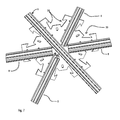
- FIG. 5 is a partial perspective view showing a six-way intermediate node of the ceiling grid network
- FIG. 6 is a top view of the intermediate node of FIG. 5 ;
- FIG. 7 is a bottom view of the intermediate node of FIG. 5 ;
- FIG. 8 is an end view of the intermediate node of FIG. 5 ;
- FIG. 9 is a partial perspective view showing details of the connection plate of the intermediate node.
- FIG. 10 is a bottom perspective view of a peripheral node
- FIG. 11 is a top view of the peripheral node of FIG. 10 ;
- FIG. 12 is a top view of the light connector for a light fixture
- FIG. 13 is a partial bottom perspective view of the light connector
- FIG. 14 is a partial perspective view of one of the projecting arms of the light connector.
- FIG. 15 is a side view of the light connector.
- the suspended ceiling system 2 includes a grid system 4 having ceiling panels 18 suspended there below.
- the grid system 4 is preferably defined by main grid members 6 which extend through aligned intermediate nodes 10 typically in a length of the ceiling system.
- Secondary grid members 8 connect adjacent nodes. These secondary grid members 8 are of a short length and do not extend through the center of the intermediate nodes 10 .
- a series of edge nodes 12 are provided at the peripheral edge of the ceiling panel system and as shown these are typically half nodes.
- the suspended ceiling panels 18 are essentially aligned beneath the grid members and preferably the grid members include a downwardly extending flange 76 (see FIGS. 5 and 7 ) which provides an alignment surface for engaging the edges of the panels, the ceiling panels cover and conceal the grid system. It is preferred that the grid system define individual cells for each panel.
- Torsion springs 26 are provided near the corners of the ceiling panels for suspending of the panels beneath the grid system 4 .
- Each of the nodes i.e. the intermediate nodes 10 and the edge nodes 12
- include torsion spring securing slots 30 These securing slots are provided near an outer edge portion of the intermediate and peripheral nodes and preferably are located in project arm 52 of the nodes.
- FIGS. 1 and 3 show a series of intermediate nodes 10 and the use of the connection plates 50 for securing of the grid members 6 and 8 in a desired configuration of the grid system.
- These connection plates include guide tracks 56 and dimple stops 58 to accurately position the various grid members and thereby accurately define the geometry and size of the cells. This assists in the assembly of the grid network and in the preferred embodiment of the invention, the grid system 4 is assembled at desk or table height. Once the grid system is assembled or partially assembled, it can be raised to the ceiling height and suspended from fixed structural members.
- the series of main grid members 6 extending through at least some of the connection plates adds to the structural integrity of the grid system.
- the connection plates 50 form an effective structural connection with the main and secondary grid members.
- the partial perspective view of FIG. 4 includes details of a light connector 100 having an integral frame that forms part of the ceiling grid system and preferable forms part of a main axis with other main grid members 6 .
- An electrical light fixture can be received into the center recess 101 and panels can be suspended at the longitudinal edges 106 of light connector 100 .
- the light connector principle can also be used for other ceiling fixtures including diffuser grates for air ventilation systems and other applications.
- FIGS. 2 , 5 , 6 , 7 , 8 and 9 show details of the grid members and the connection at an intermediate node using the connection plate 50 .
- a six way connection plate 50 having six projecting arms 52 and each arm is at an angle relative to the adjacent arm of 60°.
- Each projecting arm 52 is designed to engage and appropriately align either a secondary grid member 8 or a main grid member 6 if the grid network allows for main grid members.
- Each projecting arm includes guide dimples 54 that collectively define a guide track 56 centered on each arm 52 with this guide track being adapted to engage the top flanges 71 of a main grid member 6 or a secondary grid member 8 .
- connection plate 50 In the preferred connection plate 50 as shown in FIGS. 2 and 9 , two aligned projecting arms 52 a cooperate to define a center guide track which passes through the connection plate 50 and is adapted to engage a main grid member 6 .
- This guide track is generally shown as 75 in FIG. 9 .
- This guide track not only includes securing slot 62 provided in each of the projecting arms 52 a , but it also includes extended main securing slots 64 . These main securing slots are interior to the projecting arms (i.e. the main securing slots are located closer to the center point 110 of the connection plate).
- the connection plate 50 includes guide dimples 54 , defining the guide tracks and also includes dimple stops 58 .
- Each arm 52 includes guide dimples 54 (i.e. four guide dimples that engage the edges of the secondary grid members 8 to align the grid members relative to the projecting arm.)
- a dimple stop 58 is associated with each of the projecting arms for engaging a secondary grid member and provide a stop face spaced from the center of the connection plate. The guide track and stop face allow an installer to accurately secure the secondary grid members 8 to the connection plate and accurately define cells of the grid system.
- FIGS. 2 , 5 , 6 , 7 and 8 The appropriate connection of the secondary grid members 8 and the main grid member 6 is shown in FIGS. 2 , 5 , 6 , 7 and 8 .
- Each of the projecting arms 52 or 52 a also include torsion spring securing slots 30 and typically adjacent arms have opposed securing slots 30 . These securing slots are spaced outwardly from the center of the connection plate 8 and are also placed outwardly from the ends of the secondary grid members 8 . This simplifies securement of the torsion spring to the ceiling panels as the suspension points are positioned along the sides of the panels.
- FIGS. 2 , 5 and 8 illustrate the cross section of the main grid members 6 and the secondary grid members 8 .
- This cross section is a modified ‘I’ beam type structure with the securing slot 70 provided on an upper surface thereof for receiving screw fasteners 120 that pass through the connection plate 50 .
- This slot 70 also includes outwardly extending flanges 71 for positively engaging the lower surface of the connection plate and the guide tracks.
- the grid members include intermediate cross flanges 72 and 74 and a projecting centered web 76 .
- the grid members of this section are preferably manufactured as an extruded aluminum or aluminum alloy component and are easily cut to the appropriate length. This structure is easily cut at the time of manufacture and can also be cut on site at the time of installation.
- connection plate includes a wire connector for securing to the structural components or it may include a threaded rod or other rod type connector.
- connection plate 50 is preferably punched or diecut and is inexpensive to manufacture. It is sized to overlap beyond the ends of the secondary grid members 8 to allow the torsion spring securing slots 30 to be significantly spaced from the center point of the connection plate.
- the particular relationship of the secondary grid members and the main grid member can be appreciated from a review of FIG. 8 . It can be seen that the secondary grid members are spaced from the center of the connection plate 50 as the secondary grid members have engaged the various dimple stops 58 . The main grid member extends completely across the connection plate 50 .
- connection plate of the structure is easily manufactured and it can also be manufactured in relatively small run lots.
- FIGS. 4 and 11 through 14 A more specialized connection assembly for the grid network is shown in FIGS. 4 and 11 through 14 .
- the light connector 100 is used and has an open center recess 101 for receiving a light fixture.
- the light connector 100 includes a projecting peripheral flange 102 and has a series of projecting arms 104 that extend outwardly from the peripheral flange. Each of these projecting arms include a guide track for receiving the connecting member and guide dimples and a dimple stop are associated with each of the projecting arms as described with respect to connector plate 50 .
- the light connector 100 provides an accurate pattern for assembly of the grid members to accurately define the grid system.
- the cooperating suspended ceiling panels abutting the light connector are of a particular size and preferably include a metal frame about the edges thereof. These frames cooperate with the downwardly projecting web of the grid members to accurately position the panels within the cell.
- the panel shapes are essentially standard with a truncated edge for abutant with the light connector. These modified panels are of a predetermined shape easily manufactured. This allows for convenient assembly on site and accurate connection.
- the light connector 100 forms part of the grid system and accurately connects with grid members using projecting arms 104 . This determines the panel shapes that cooperate with the light connector 100 .
- the light connector 100 as shown defines two intermediate nodes.
- FIGS. 10 and 11 show details of the connector plates 120 used to define edge nodes 12 .
- the edge nodes are half of the intermediate nodes as the periphery of the ceiling system is generally adjacent a wall.
- the edge nodes will be designed to allow connection at an inside special angle between abutting walls.
- These connection plates include projecting arms, guide tracks, dimple guides and dimple stops to simplify assembly and provide accuracy.
- the suspended ceiling system is based on engineering drawings and the necessary components are manufactured and provided to the job site. Additional components may also be provided to address job site conditions that are only realized at time of installation. By providing some additional connection plates 50 these can be modified on site to meet the particular needs that may arise.
- the system is cost effective to manufacture and cost effective to install.
- the system has also been described with respect to a six way connector, however it is also possible to use an eight way connector for defining an octagonal-type grid network.
- An eight way connector can also be used to allow the suspension of a square panel which is typically defined between octagonal-type ceiling panels.
- Other grid networks and connection plates allow for custom ceiling solutions. Some of these grid systems will not allow main grid members and only secondary grid members will be used. Therefore, the present system is not limited to the six way system shown that is typically used with equilateral triangles. This system is readily adapted for defining different grid networks as may be required.
Landscapes
- Engineering & Computer Science (AREA)
- Architecture (AREA)
- Physics & Mathematics (AREA)
- Electromagnetism (AREA)
- Civil Engineering (AREA)
- Structural Engineering (AREA)
- Residential Or Office Buildings (AREA)
- Non-Portable Lighting Devices Or Systems Thereof (AREA)
Abstract
Description
Claims (14)
Priority Applications (2)
| Application Number | Priority Date | Filing Date | Title |
|---|---|---|---|
| US12/659,497 US8079192B2 (en) | 2010-03-11 | 2010-03-11 | Suspended ceiling grid system |
| US13/328,505 US8474200B2 (en) | 2010-03-11 | 2011-12-16 | Suspended ceiling grid system |
Applications Claiming Priority (1)
| Application Number | Priority Date | Filing Date | Title |
|---|---|---|---|
| US12/659,497 US8079192B2 (en) | 2010-03-11 | 2010-03-11 | Suspended ceiling grid system |
Related Child Applications (1)
| Application Number | Title | Priority Date | Filing Date |
|---|---|---|---|
| US13/328,505 Continuation-In-Part US8474200B2 (en) | 2010-03-11 | 2011-12-16 | Suspended ceiling grid system |
Publications (2)
| Publication Number | Publication Date |
|---|---|
| US20110219718A1 US20110219718A1 (en) | 2011-09-15 |
| US8079192B2 true US8079192B2 (en) | 2011-12-20 |
Family
ID=44558594
Family Applications (1)
| Application Number | Title | Priority Date | Filing Date |
|---|---|---|---|
| US12/659,497 Active US8079192B2 (en) | 2010-03-11 | 2010-03-11 | Suspended ceiling grid system |
Country Status (1)
| Country | Link |
|---|---|
| US (1) | US8079192B2 (en) |
Cited By (9)
| Publication number | Priority date | Publication date | Assignee | Title |
|---|---|---|---|---|
| US20100027199A1 (en) * | 2008-10-02 | 2010-02-04 | Diamond Displays, Inc. | Trade show display mount |
| US20120023853A1 (en) * | 2010-07-27 | 2012-02-02 | Decoustics Limited | Ceiling panel clip |
| US9303405B2 (en) | 2013-08-13 | 2016-04-05 | Chris A. Nelson | Modular truss system |
| EP3156552A1 (en) * | 2015-10-13 | 2017-04-19 | SAS International Limited | A suspended ceiling |
| US9879424B1 (en) * | 2017-06-07 | 2018-01-30 | Usg Interiors, Llc | Torsion spring panel bars and construction method |
| US10233640B1 (en) | 2016-09-27 | 2019-03-19 | Quicklip Llc | Drop ceiling attachment assembly |
| US10676925B2 (en) * | 2018-03-21 | 2020-06-09 | Awi Licensing Llc | Ceiling system having a plurality of different panels |
| US20210404179A1 (en) * | 2020-06-30 | 2021-12-30 | Usg Interiors, Llc | Modular dynamic acoustic ceiling panel |
| US11286666B2 (en) * | 2016-09-08 | 2022-03-29 | Polygrid Pty Ltd | Assemblies for suspending ceiling panels |
Families Citing this family (7)
| Publication number | Priority date | Publication date | Assignee | Title |
|---|---|---|---|---|
| US20110167747A1 (en) * | 2010-01-12 | 2011-07-14 | Chien-Teh Huang | Ceiling with stabilizing frame |
| US10690305B2 (en) * | 2014-10-28 | 2020-06-23 | Ideal Industries Lighting Llc | Edge lit fixture |
| US11079076B2 (en) | 2014-10-28 | 2021-08-03 | Ideal Industries Lighting Llc | Edge lit fixture |
| CN111794512B (en) * | 2020-07-18 | 2021-09-21 | 福建大华建设工程股份有限公司 | Overhead layer ceiling construction method |
| US20220025652A1 (en) * | 2020-07-21 | 2022-01-27 | Axis Lighting Inc. | Ceiling panel assembly |
| CN112627423A (en) * | 2020-12-15 | 2021-04-09 | 深圳市艺选室内装饰设计有限公司 | Assembled ceiling decorative structure |
| US11940121B2 (en) | 2022-08-30 | 2024-03-26 | Abl Ip Holding Llc | Light fixture for ceiling grid |
Citations (16)
| Publication number | Priority date | Publication date | Assignee | Title |
|---|---|---|---|---|
| US22273A (en) * | 1858-12-14 | Improvement in sewing-machines | ||
| US4019300A (en) * | 1975-08-04 | 1977-04-26 | Roblin Industries, Inc. | Suspended ceiling structure |
| US4438613A (en) * | 1981-06-25 | 1984-03-27 | Decoustics Limited | Suspended ceiling panel system |
| US4548010A (en) * | 1981-06-25 | 1985-10-22 | Decoustics Limited | Concealed suspended ceiling system |
| US5241799A (en) * | 1991-12-10 | 1993-09-07 | Chicago Metallic Corporation | Open cell lay-in panel |
| US5428930A (en) * | 1993-07-23 | 1995-07-04 | Decoustics Limited | Concealed grid ceiling panel system |
| US6029413A (en) * | 1998-10-14 | 2000-02-29 | Compas, Jr.; Albert W. | Dropped ceiling support frame |
| US6536167B2 (en) * | 2001-04-04 | 2003-03-25 | John Glavan | Structural assembly |
| US20030230043A1 (en) * | 2002-06-14 | 2003-12-18 | Likozar Martin E. | Scalable suspension system for dome shaped ceilings |
| US20040118068A1 (en) * | 2002-12-19 | 2004-06-24 | Dennis Kliegle | Accessible ceiling grid system |
| US20050034402A1 (en) * | 2003-08-12 | 2005-02-17 | Johnson Michael W. | Torsion spring mount for suspended ceiling panels |
| US20060162283A1 (en) * | 2005-01-13 | 2006-07-27 | Moser Rossel Roberto F | Removable ceiling panel |
| US20060218871A1 (en) * | 2005-04-04 | 2006-10-05 | Wendt Alan C | Clip for attaching ceiling panels to T-grid |
| US20100005747A1 (en) * | 2008-07-14 | 2010-01-14 | Usg Interiors, Inc. | Seismic clip for grid tee control joint |
| US7673429B2 (en) * | 2004-01-16 | 2010-03-09 | Worthington Armstrong Venture | Suspended ceiling grid network utilizing seismic separation joint clips |
| US7770338B2 (en) * | 2004-08-10 | 2010-08-10 | Abdessatar Nefzi | Method for producing triangular elements designed for the manufacture of structures and resulting triangular elements |
-
2010
- 2010-03-11 US US12/659,497 patent/US8079192B2/en active Active
Patent Citations (20)
| Publication number | Priority date | Publication date | Assignee | Title |
|---|---|---|---|---|
| US22273A (en) * | 1858-12-14 | Improvement in sewing-machines | ||
| US4019300A (en) * | 1975-08-04 | 1977-04-26 | Roblin Industries, Inc. | Suspended ceiling structure |
| US4438613A (en) * | 1981-06-25 | 1984-03-27 | Decoustics Limited | Suspended ceiling panel system |
| US4548010A (en) * | 1981-06-25 | 1985-10-22 | Decoustics Limited | Concealed suspended ceiling system |
| US5241799A (en) * | 1991-12-10 | 1993-09-07 | Chicago Metallic Corporation | Open cell lay-in panel |
| US5428930A (en) * | 1993-07-23 | 1995-07-04 | Decoustics Limited | Concealed grid ceiling panel system |
| US5535566A (en) * | 1993-07-23 | 1996-07-16 | Decoustics Limited | Concealed grid ceiling panel system |
| US6029413A (en) * | 1998-10-14 | 2000-02-29 | Compas, Jr.; Albert W. | Dropped ceiling support frame |
| US6536167B2 (en) * | 2001-04-04 | 2003-03-25 | John Glavan | Structural assembly |
| US20030230043A1 (en) * | 2002-06-14 | 2003-12-18 | Likozar Martin E. | Scalable suspension system for dome shaped ceilings |
| US20040118068A1 (en) * | 2002-12-19 | 2004-06-24 | Dennis Kliegle | Accessible ceiling grid system |
| US6971210B2 (en) * | 2002-12-19 | 2005-12-06 | Owens Corning Fiberglas Technology, Inc. | Accessible ceiling grid system |
| US20050034402A1 (en) * | 2003-08-12 | 2005-02-17 | Johnson Michael W. | Torsion spring mount for suspended ceiling panels |
| US7673429B2 (en) * | 2004-01-16 | 2010-03-09 | Worthington Armstrong Venture | Suspended ceiling grid network utilizing seismic separation joint clips |
| US7770338B2 (en) * | 2004-08-10 | 2010-08-10 | Abdessatar Nefzi | Method for producing triangular elements designed for the manufacture of structures and resulting triangular elements |
| US20060162283A1 (en) * | 2005-01-13 | 2006-07-27 | Moser Rossel Roberto F | Removable ceiling panel |
| US20060218871A1 (en) * | 2005-04-04 | 2006-10-05 | Wendt Alan C | Clip for attaching ceiling panels to T-grid |
| US7478506B2 (en) * | 2005-04-04 | 2009-01-20 | Usg Interiors, Inc. | Clip for attaching ceiling panels to T-grid |
| US20100005747A1 (en) * | 2008-07-14 | 2010-01-14 | Usg Interiors, Inc. | Seismic clip for grid tee control joint |
| US7770349B2 (en) * | 2008-07-14 | 2010-08-10 | Usg Interiors, Inc. | Seismic clip for grid tee control joint |
Cited By (16)
| Publication number | Priority date | Publication date | Assignee | Title |
|---|---|---|---|---|
| US9293070B2 (en) * | 2008-10-02 | 2016-03-22 | Diamond Displays, Inc. | Trade show display mount |
| US20100027199A1 (en) * | 2008-10-02 | 2010-02-04 | Diamond Displays, Inc. | Trade show display mount |
| US20120023853A1 (en) * | 2010-07-27 | 2012-02-02 | Decoustics Limited | Ceiling panel clip |
| US8683768B2 (en) * | 2010-07-27 | 2014-04-01 | Certainteed Canada, Inc. | Ceiling panel clip |
| US9303405B2 (en) | 2013-08-13 | 2016-04-05 | Chris A. Nelson | Modular truss system |
| EP3156552A1 (en) * | 2015-10-13 | 2017-04-19 | SAS International Limited | A suspended ceiling |
| US11286666B2 (en) * | 2016-09-08 | 2022-03-29 | Polygrid Pty Ltd | Assemblies for suspending ceiling panels |
| US12227943B2 (en) | 2016-09-08 | 2025-02-18 | Polygrid Pty Ltd | Assemblies for suspending ceiling panels |
| US10233640B1 (en) | 2016-09-27 | 2019-03-19 | Quicklip Llc | Drop ceiling attachment assembly |
| US9879424B1 (en) * | 2017-06-07 | 2018-01-30 | Usg Interiors, Llc | Torsion spring panel bars and construction method |
| US10676925B2 (en) * | 2018-03-21 | 2020-06-09 | Awi Licensing Llc | Ceiling system having a plurality of different panels |
| US11725384B2 (en) | 2018-03-21 | 2023-08-15 | Awi Licensing Llc | Ceiling system having a plurality of different panels |
| US10995489B2 (en) | 2018-03-21 | 2021-05-04 | Awi Licensing Llc | Ceiling system having a plurality of different panels |
| US12258756B2 (en) | 2018-03-21 | 2025-03-25 | Awi Licensing Llc | Ceiling system having a plurality of different panels |
| US20210404179A1 (en) * | 2020-06-30 | 2021-12-30 | Usg Interiors, Llc | Modular dynamic acoustic ceiling panel |
| US11692345B2 (en) * | 2020-06-30 | 2023-07-04 | Usg Interiors, Llc | Modular dynamic acoustic ceiling panel |
Also Published As
| Publication number | Publication date |
|---|---|
| US20110219718A1 (en) | 2011-09-15 |
Similar Documents
| Publication | Publication Date | Title |
|---|---|---|
| US8079192B2 (en) | Suspended ceiling grid system | |
| US8474200B2 (en) | Suspended ceiling grid system | |
| US10844591B2 (en) | Panel system and support member for use with the same | |
| US10288269B2 (en) | Ceiling system | |
| JP2017520693A (en) | Suspended ceiling clip | |
| US10100519B2 (en) | Ceiling system and mounting bracket for use with the same | |
| US10371371B2 (en) | Ventilation kit and recessed light fixture assembly with ventilation | |
| US20190024372A1 (en) | High strength grid member for suspended ceilings | |
| US20170051505A1 (en) | Channel for interior glass panel | |
| CA2696225C (en) | Suspended ceiling grid system | |
| US4257205A (en) | Attachment system for suspended drywall ceiling panels | |
| US8534014B2 (en) | Magnetic cross tees | |
| CA2798897C (en) | Suspended ceiling grid system | |
| US3506822A (en) | Universal air handling troffer frame | |
| US10962207B2 (en) | Hub for lighting at grid intersection | |
| US12152387B2 (en) | Ceiling grid support bar, and ceiling system | |
| US12259113B2 (en) | Light fixture for low profile installation | |
| CN212802201U (en) | Corner connecting piece and corner keel assembly for installing suspended ceiling | |
| WO1993003307A1 (en) | A lighting assembly and bracket therefor | |
| EP3218553A1 (en) | Ceiling system | |
| IE41759B1 (en) | Improvements relating to ceilings and like structures |
Legal Events
| Date | Code | Title | Description |
|---|---|---|---|
| AS | Assignment |
Owner name: DECOUSTICS LIMITED, CANADA Free format text: ASSIGNMENT OF ASSIGNORS INTEREST;ASSIGNORS:GERKES, MARTIN DANIEL;KOLGA, HELKKI;WHITE, RONALD;REEL/FRAME:024943/0122 Effective date: 20100819 Owner name: DECOUSTICS LIMITED, CANADA Free format text: ASSIGNMENT OF ASSIGNORS INTEREST;ASSIGNORS:GERKES, MARTIN DANIEL;KOLGA, HEIKKI;WHITE, RONALD;REEL/FRAME:024917/0779 Effective date: 20100819 |
|
| STCF | Information on status: patent grant |
Free format text: PATENTED CASE |
|
| AS | Assignment |
Owner name: CERTAINTEED CANADA, INC., CANADA Free format text: MERGER;ASSIGNOR:DECOUSTICS LIMITED;REEL/FRAME:032080/0940 Effective date: 20131231 |
|
| FPAY | Fee payment |
Year of fee payment: 4 |
|
| MAFP | Maintenance fee payment |
Free format text: PAYMENT OF MAINTENANCE FEE, 8TH YEAR, LARGE ENTITY (ORIGINAL EVENT CODE: M1552); ENTITY STATUS OF PATENT OWNER: LARGE ENTITY Year of fee payment: 8 |
|
| MAFP | Maintenance fee payment |
Free format text: PAYMENT OF MAINTENANCE FEE, 12TH YEAR, LARGE ENTITY (ORIGINAL EVENT CODE: M1553); ENTITY STATUS OF PATENT OWNER: LARGE ENTITY Year of fee payment: 12 |